Reports 1-1 of 1 Clear search Modify search
VIS (BS)
ayaka.shoda - 9:58 Monday 04 December 2017 (3768) Print this report
BS control works from 29th Nov - 1st Dec.

Sorry for the summarized task report...

On 29th Nov. (Enzo, Kozu, Shoda): damping control on IM stage

We implemented the damping control system at IM stages.
However, it seems that the loop cannot be closed perfectly because of the resonance at high frequencies and couplings.
A little bit more tuning is required.

Damping system for the IP stage will be implemented soon with the same method.

On 30th Nov. (Mark, Shoda): Oplev calibration

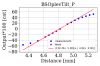
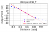
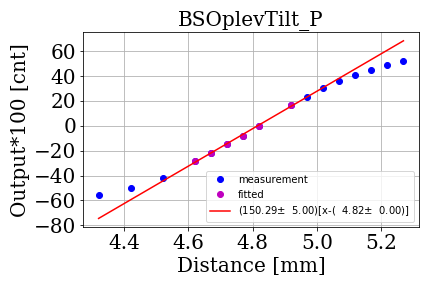
We measured the calibration factor from the beam spot displacement (m) to count.
Here, we just ignored the large coupling between the YAW and PITCH caused by the steering mirror, and actuate the QPD stage in horizontal and vertical to see the change in the count.
See the uploaded graph for the results.

And the rotation matrix to compensate the PITCH/YAW coupling was measured by Mark. (Please upload, Mark!)
The final calibration factor should be calculated from both results.

On 1st Dec. (Shoda): Oplev configuration check

We have very small amount of the reflection beam as looking at the QPD sum counts.
While other PR Oplevs have the sum counts of about 30000, BS Oplev has only 1600 for tilt oplevs.

So I checked several parameters:

1. QPD gain:

we have a small switch on the QPD to change the gain. It was set as same as PRs.

2. Reflection beam:

we checked whether the reflection beam is coming from AR or HR. Since the wedge angle of the BS is very small, the reflection beam comes almost parallel. 
And we have the lower beam on the QPDs, which should be the reflection from AR because of the geometry.

3. Transmitted beam:

The blightness of the transmitted beam was checked by eyes. As far as I looked, the transmitted beam was blighter than the reflection beam.

4. Power:

I tried to check the power of the oplev beam in order to check the laser source is properly working. However, it is difficult to measure the power less than 1 mW with the power meter I grabbed. According to Nakano-kun, we have another power meter. We should use it next time we want to check.
Still the blightness of the laser source was almost same as one of PRs. I think laser source is working well. 

5. Polarization:

I rotated the input collimator in order to change the polarization of the injection beam. Then the sum number of the QPDs are increased by about 63 %. 
The sum number was increased to 2600 from 1600.
However, I did not tried fine tuning because it was time consuming to align the beam to QPDs many times after I rotated the collimator.

Images attached to this report
Comments to this report:
mark.barton - 14:26 Thursday 14 December 2017 (3835) Print this report

BS OL Diagonalization


With Shoda-san.


On 11/30 we collected data for calibration and diagonalization of the BS tilt OL and have since analyzed it. See the attached Excel spreadsheet for the raw data and full analysis.

  • We scanned the QPD horizontally with the micrometer and noted the readings in nominal yaw (K1:VIS_BS_TM_OPLEV_TILT_YAW_OUTMON). There was a fair amount of physical swing (mostly physical yaw) showing up in both nominal pitch and nominal yaw (due to poor diagonalization), so we used StripTool to look at a representative length of data and eyeball the average. There was a 100x gain (Simon's preliminary guesstimate of the µrad per count at K1:VIS_BS_TM_OPLEV_TILT_YAW_INMON) just before the point we read the signal, so we divided it out in the data analysis and made the _INMON version the reference.
  • We scanned the QPD vertically with the micrometer and noted the readings in nominal pitch (K1:VIS_BS_TM_OPLEV_TILT_PIT_OUTMON).
  • The calibration factors were -1.53 cts/mm at K1:VIS_BS_TM_OPLEV_TILT_YAW_INMON and +1.45 cts/mm at K1:VIS_BS_TM_OPLEV_TILT_PIT_INMON. These are very close, so apparently the beam is quite round at the QPD.
  • We applied yaw actuation at the IM OSEMs (K1:VIS_BS_IM_TEST_Y_OFFSET) and noted the readings in nominal yaw and pitch at the OL, and at the IM OSEMs (K1:VIS_BS_IM_DAMP_Y_INMON and K1:VIS_BS_IM_DAMP_P_INMON). We did the same with pitch actuation (K1:VIS_BS_IM_TEST_P_OFFSET).
  • We plotted the responses at the IM as a function of actuation at the IM and found pitch and yaw were already pretty much perfectly independent, so we made no attempt to do any diagonalization of the OSEMs.
  • We did similar plots for the nominal yaw and pitch at the TILT OL and found that there was very large cross-coupling. This is due to the odd angle of the first steering mirror, which bends the light from the +X,-Y direction at about 38° to the horizontal, to approximately in +X and level with the OL breadboard. Using the Y and P coefficients of the coupling matrix separately gave estimates of 61.8° and 62.8° for the angle, so the coupling is consistent with a pure rotation.
  • We derived a net calibration/diagonalization matrix taking into account:
    • The measured calibrations from QPD position to nominal yaw and pitch).
    • The measured beam path from the BS to the QPD. See klog 3616 for most of the segments of the path. We had to make a new measurement of the last segment of the path to the TILT (as opposed to LEN) QPD: 124 mm.
    • The angle of the beam at the BS (38° as estimated from CAD) which reduces the effective length of the OL in yaw by cos(theta).
    • The rotation angle introduced by the steering mirror.
  • We checked that the new matrix did in fact accurately diagonalize the original data.
  • We divided the derived matrix by 100, and then entered it in the K1:VIS-BS_TM_OPLEV_OL2EUL screen, leaving Simon's gains of 100 in place. This makes the raw and diagonalized plots more comparable.
  • However we did not get good agreement with the amount of yaw and pitch measured by the IM OSEMs. The diagonalized OL yaw was 2.17 times the IM yaw and the diagonalized OL pitch was 14.3 times the IM pitch.
  • We traced some of this to an error in the OSEM2EUL matrices for the IM: the P and Y entries were too small by a factor of 2 due to confusion about specifying the position of the OSEMs relative to the center vs. relative to the opposing OSEM. We give the correct version of the calculation in JGW-T1707205-v4, and we entered the correct matrices around 4:30 pm on Monday 12/11. That brings the OL and IM into reasonable agreement, but leaves a factor around 7 to be accounted for in pitch. A modest amount more pitch response at the IM than at the OL could be explained by the BF and IRM tilting opposite to the IM and BS, but we have the reverse of that, so there may be a dumb mistake still lurking.
Non-image files attached to this comment
Search Help
×

Warning

×