[Fujimoto, Yokozawa, Komori]
Summary
We could not observe any error signals from the IFO REFL RFPDs, so we were unable to measure the IMC length today.
We should check the RF cable connections around the EOM, RFPDs, demodulation boards, and related electronics.
Details
Before adjusting the IMC length and the RF sideband frequencies, we tried to confirm the current IMC length.
The measurement method was exactly the same as that used previously (klog:29385).
We tried to tune the RF sideband frequency and the input offset while exciting the laser frequency through DGCARM, and monitored the peak height in the power spectrum of the error signal measured at IFO REFL.
However, we could not observe any peaks in the error-signal spectra measured by the REFL RFPDs, even when changing the RF frequency by 10 Hz or more.
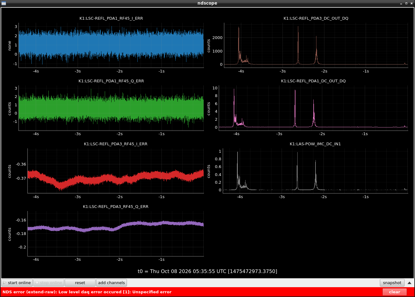
We confirmed that the DC powers measured at the IMC transmission and the two IFO REFL PDs (PDA1 and PDA3) were fluctuating.
This indicates that the laser frequency was indeed being excited and that the DC ports of both REFL PDs appeared to be functioning normally.
On the other hand, we could not observe any signal from the RF-demodulated ports at any time.
We should be able to observe a PDH-like signal from these PDs during an IMC cavity scan, but no such signal was observed (Fig. 1).
Therefore, we suspect that there may be an issue with the RF signal path, such as disconnected or incorrectly connected cables around the EOM, RFPDs, or demodulation boards.
Unless we have overlooked something simple, an inspection of the components and cable connections inside the tunnel will be necessary.