Reports 1-1 of 1 Clear search Modify search
VIS (EX)
takafumi.ushiba - 22:27 Wednesday 07 October 2026 (37625) Print this report
Health check of ETMX

This log shows health check results of ETMX payload.

Summary:

TM H1 actuator might have a problem.

Detail:

I ran the automesurement scripts and checked the results of ETMX payload.
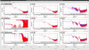
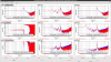
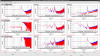
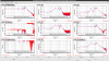
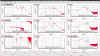
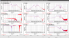
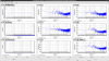
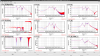
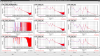
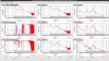
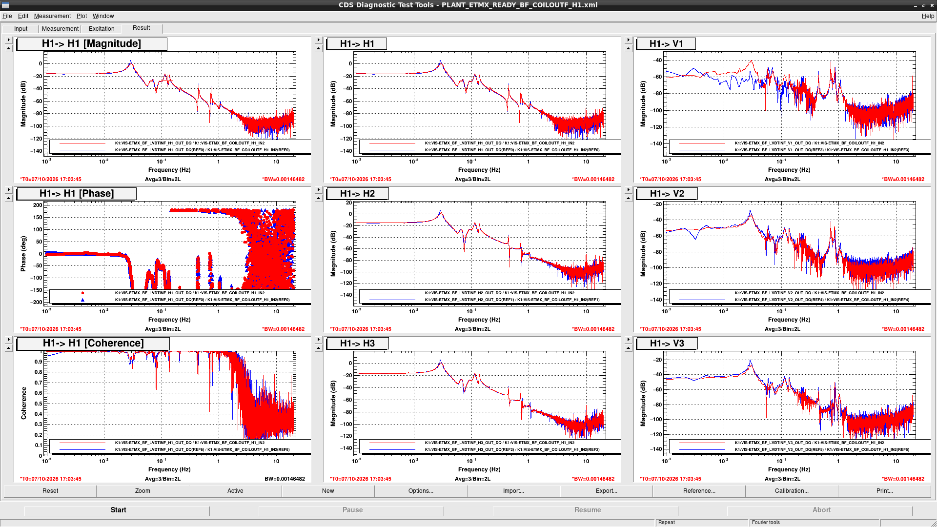
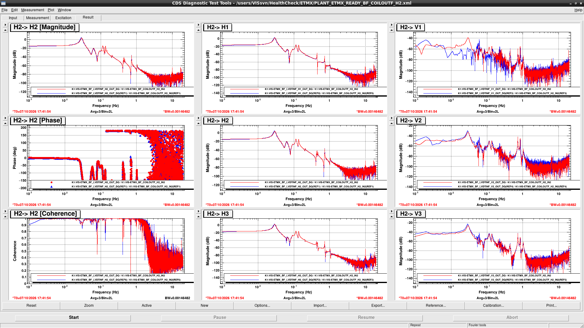
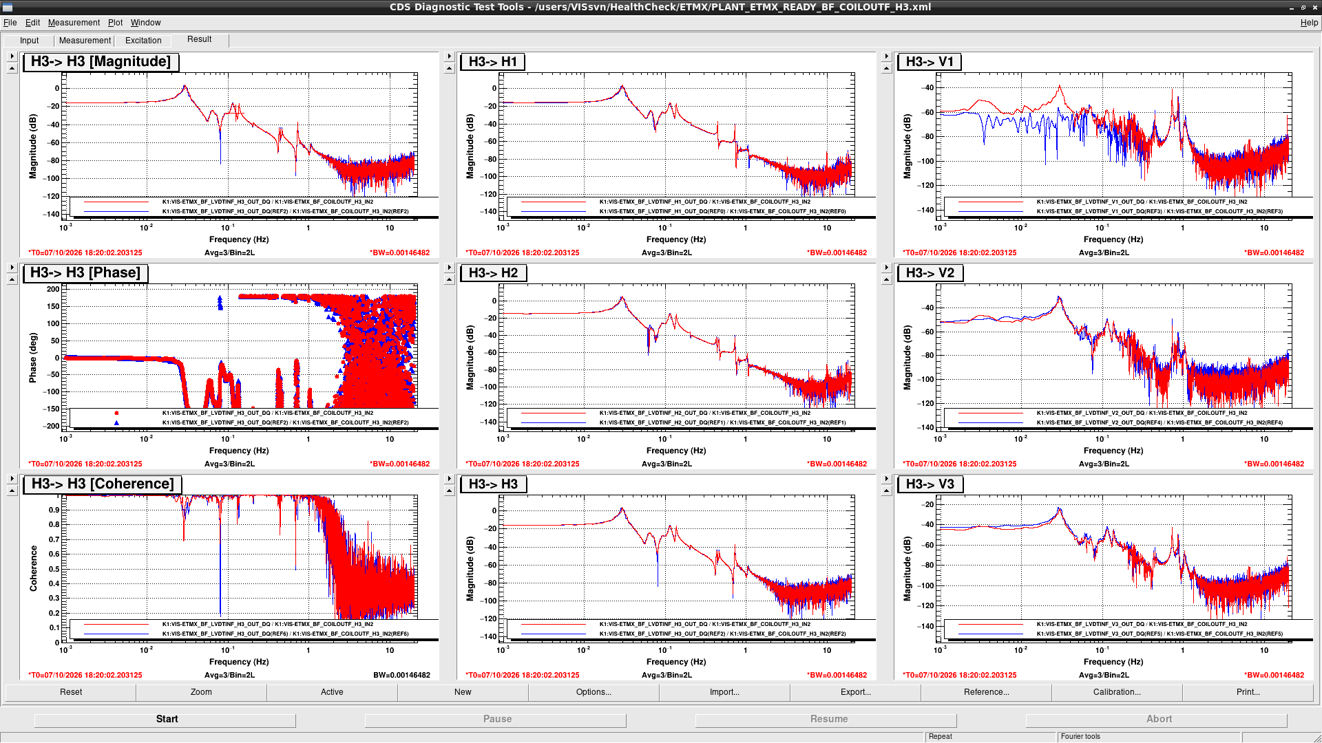
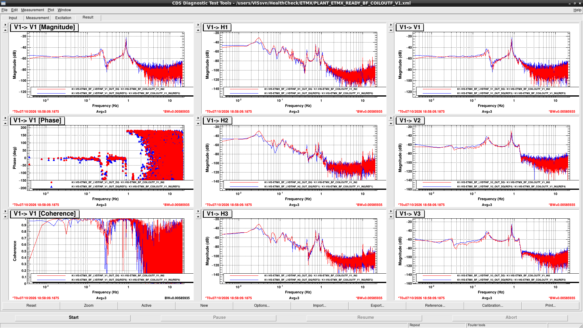
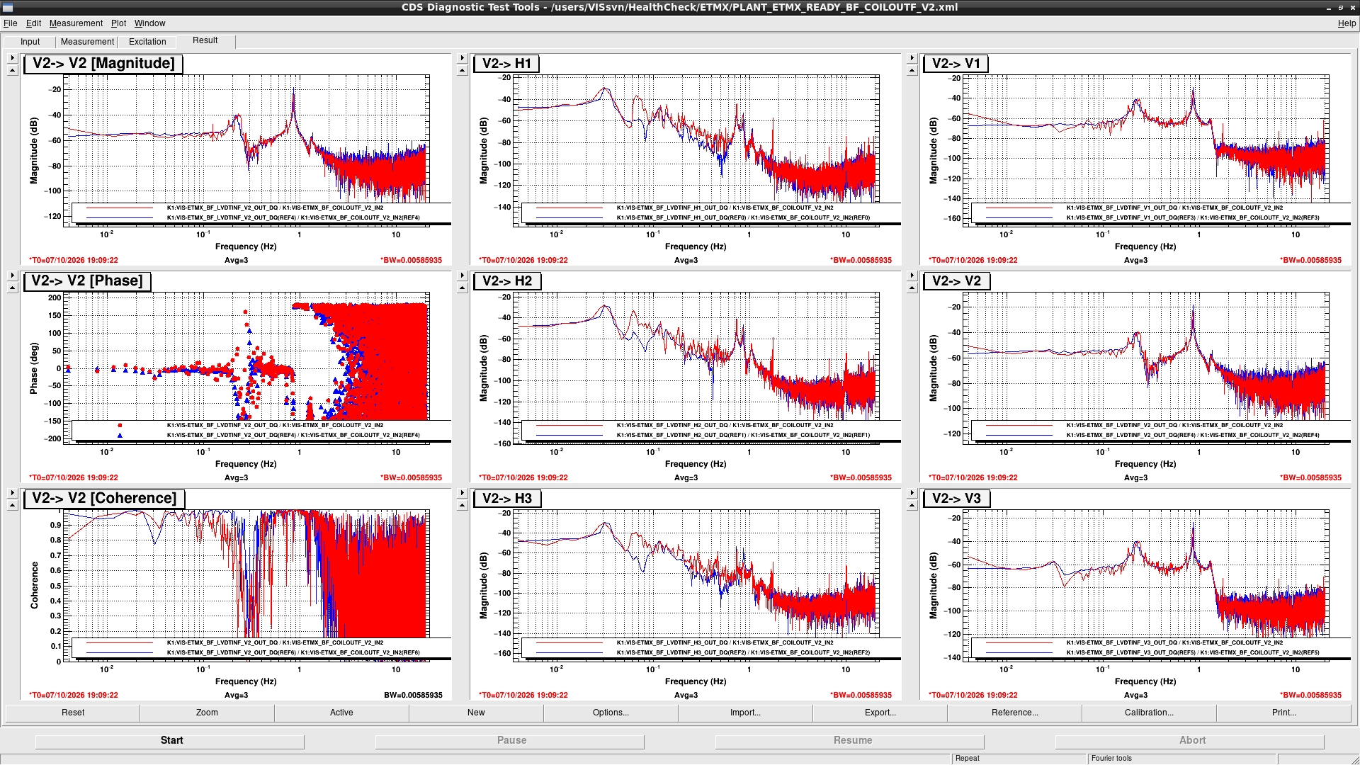
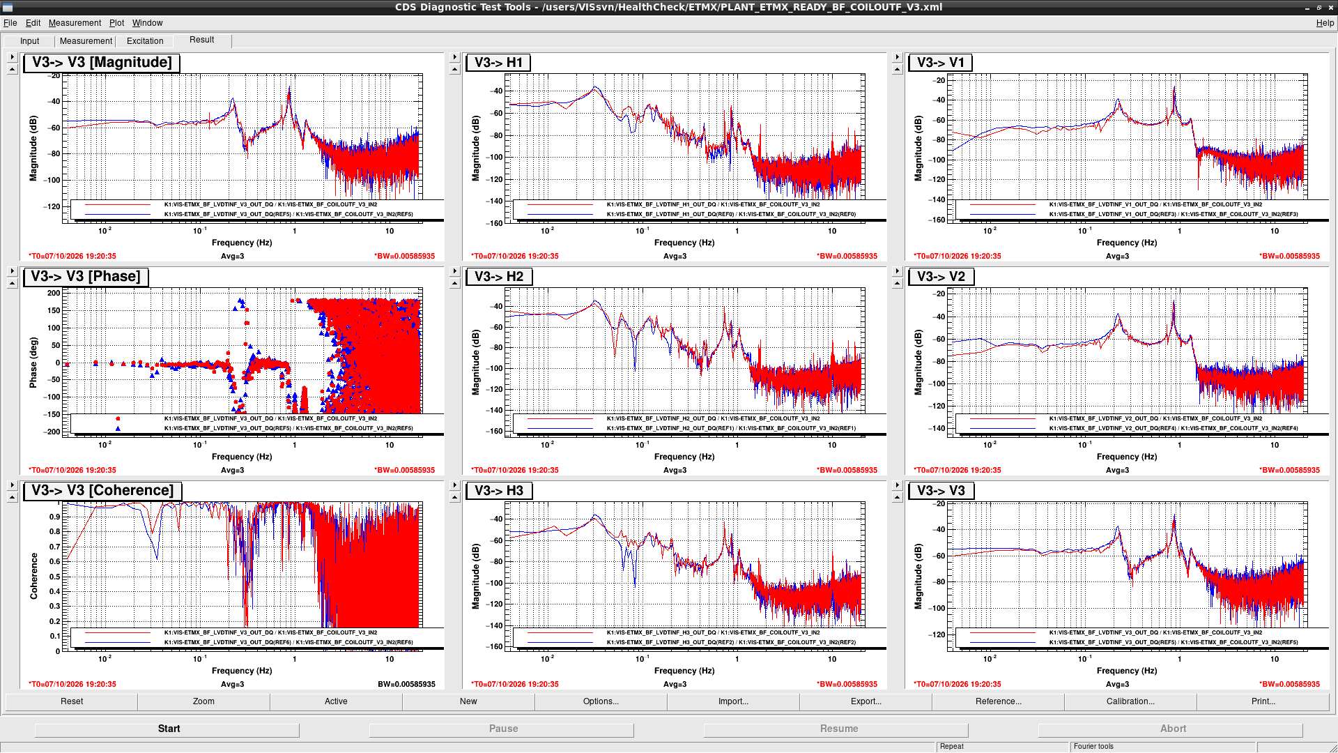
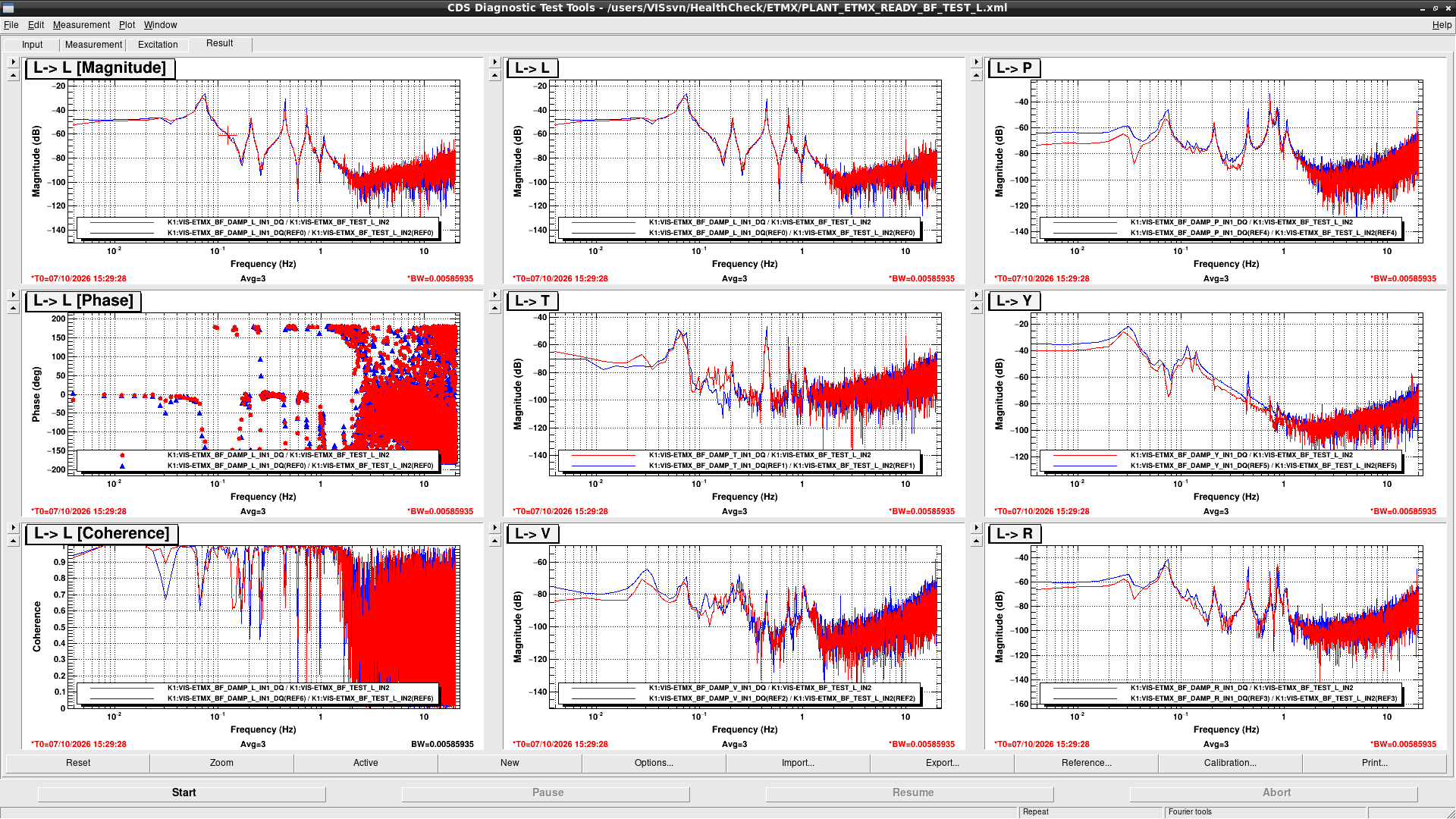
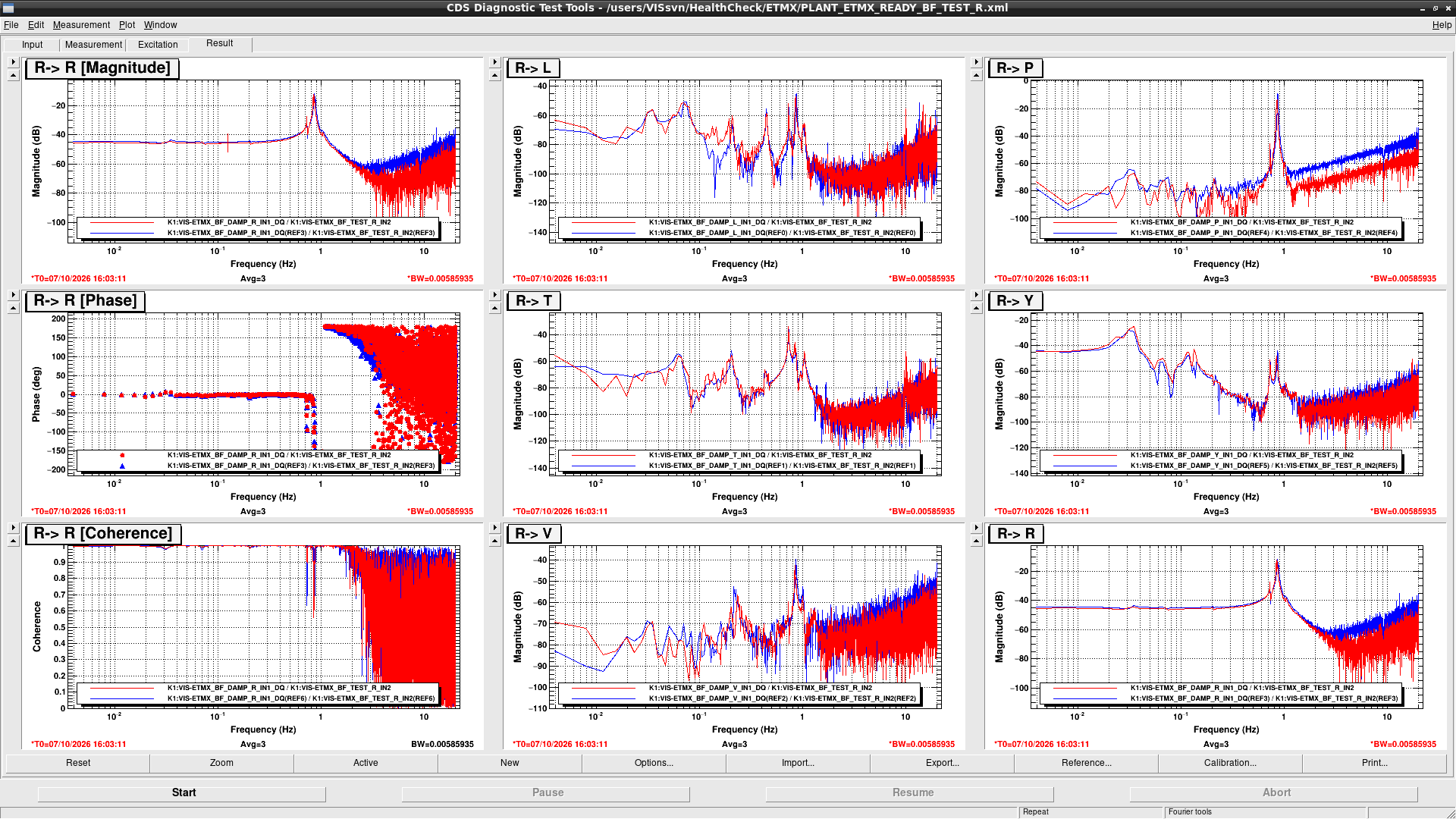
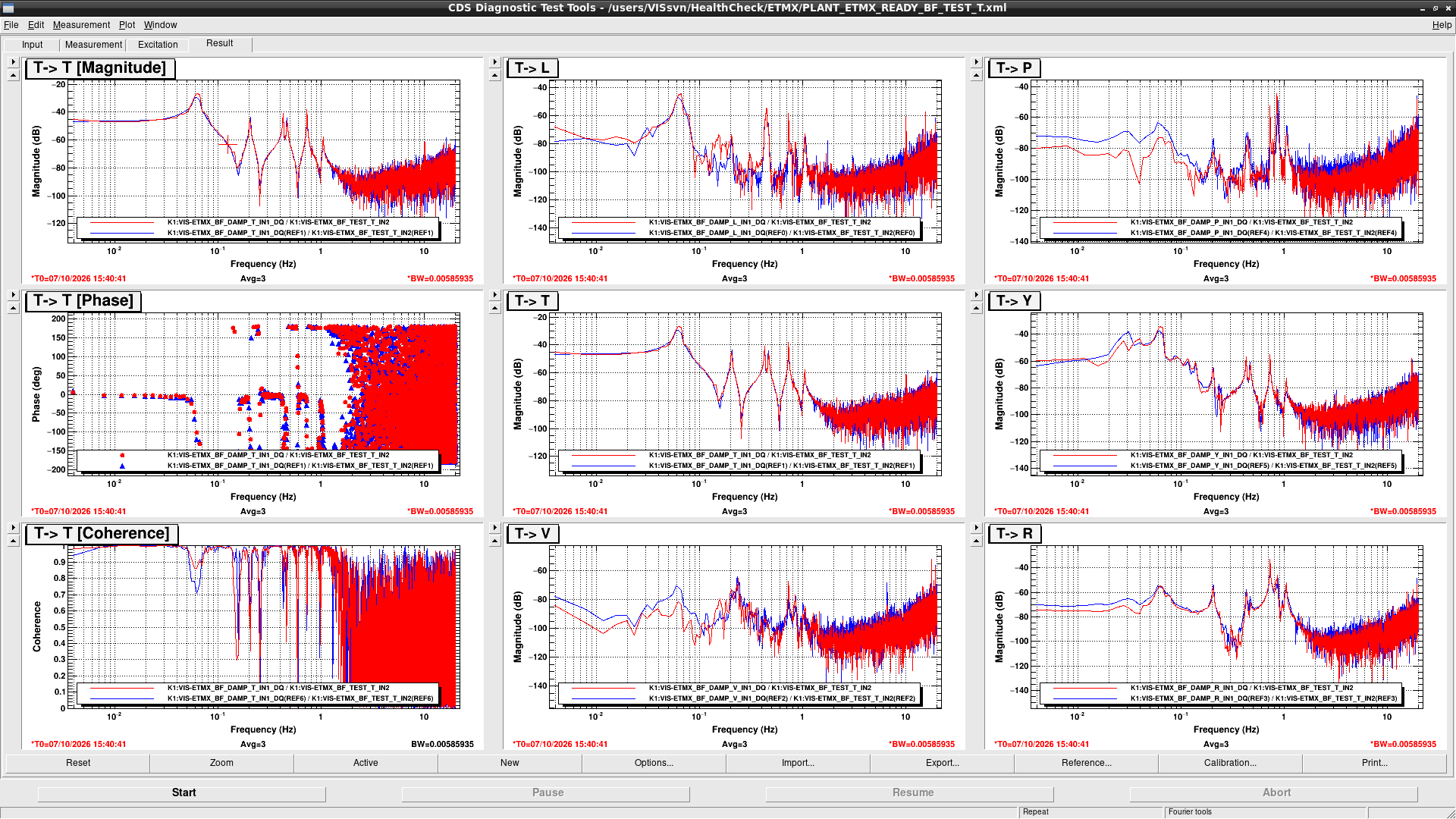
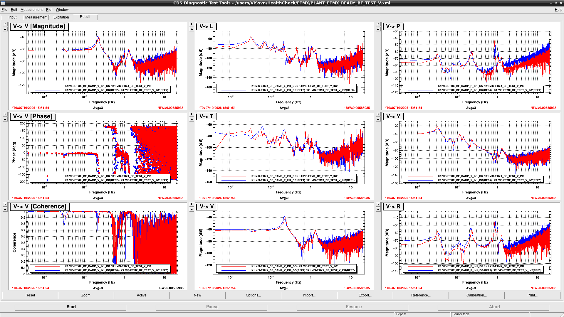
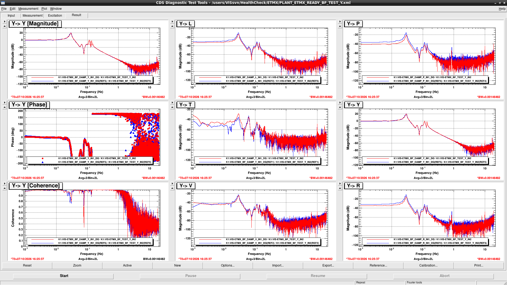
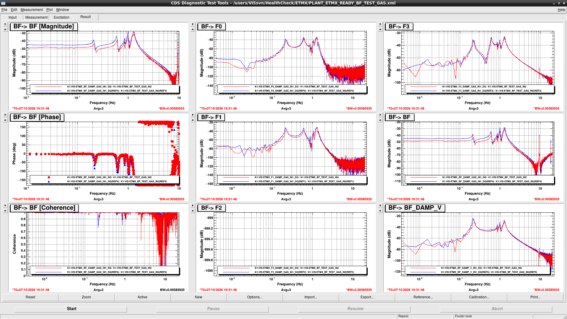
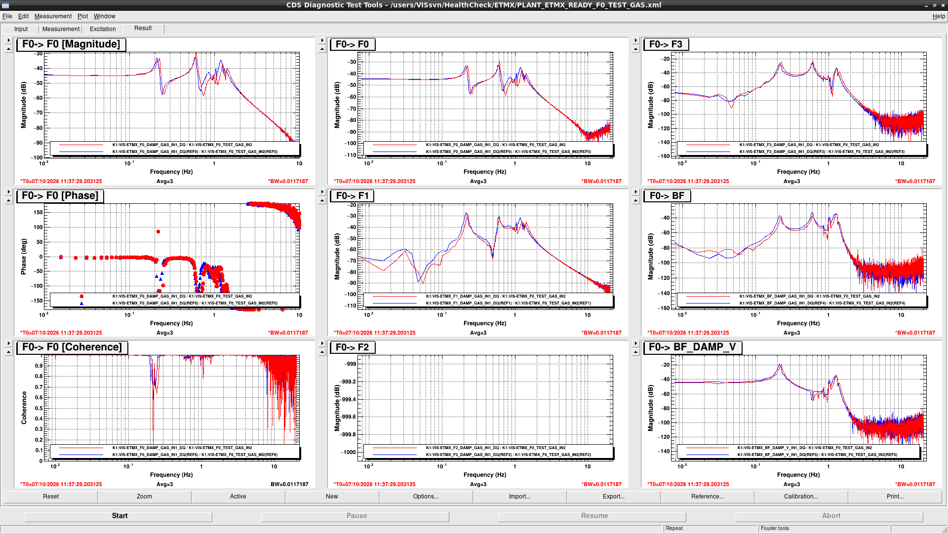
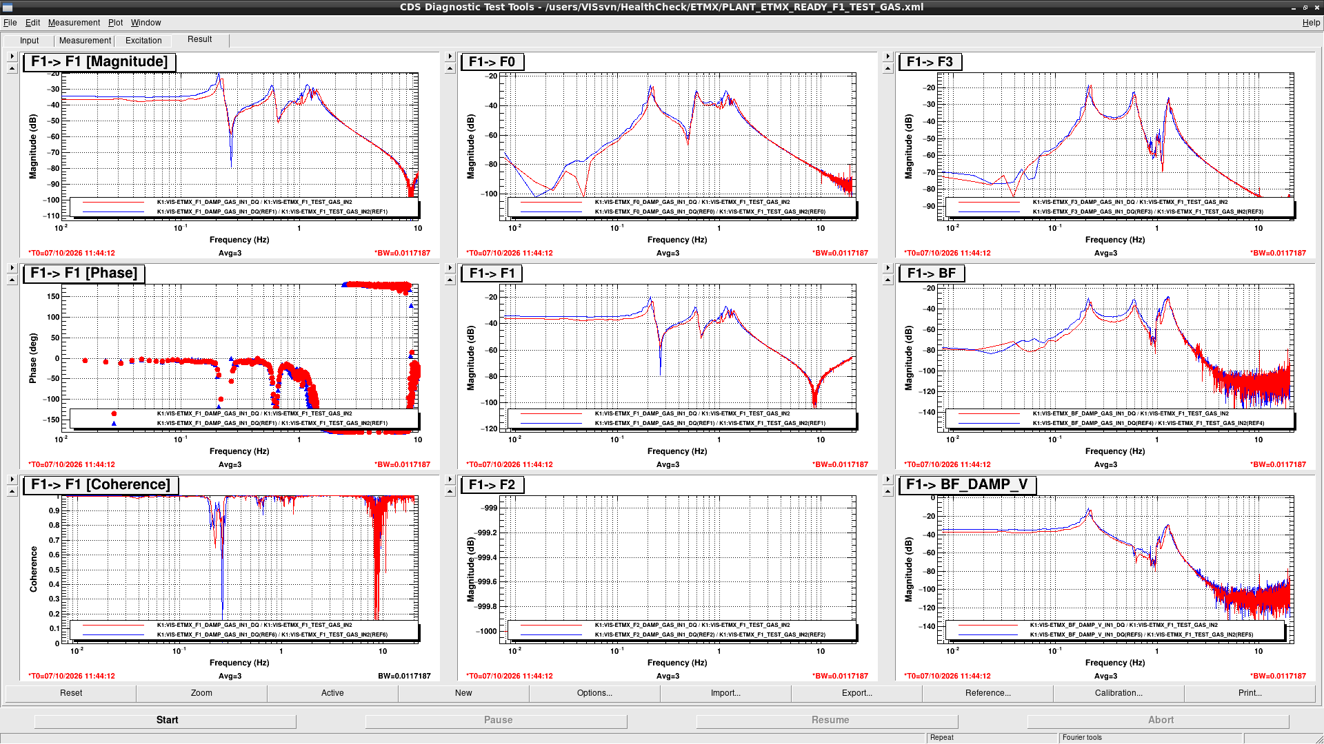
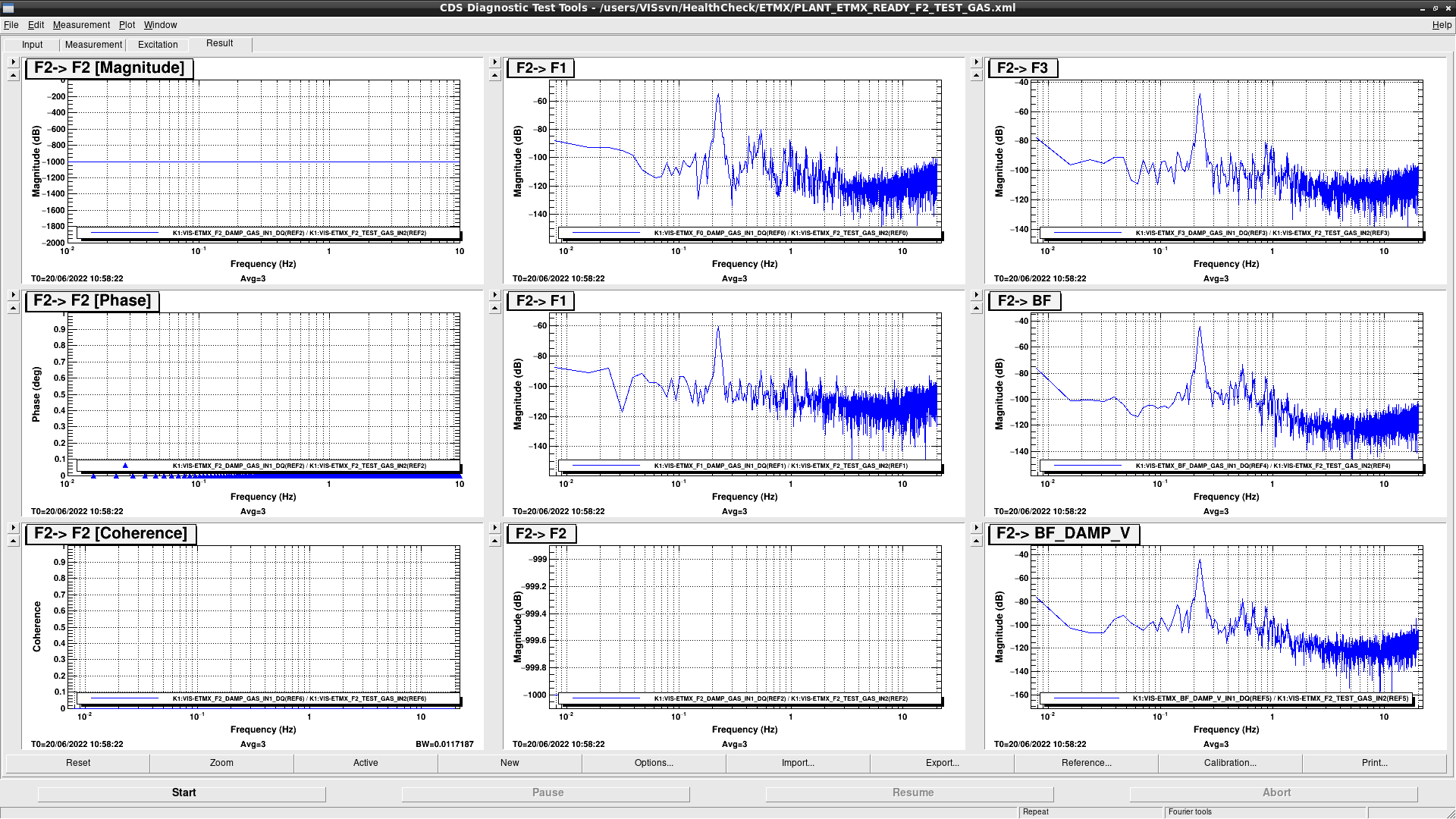
Figure 1 - 28 show the graphs of each measurement.

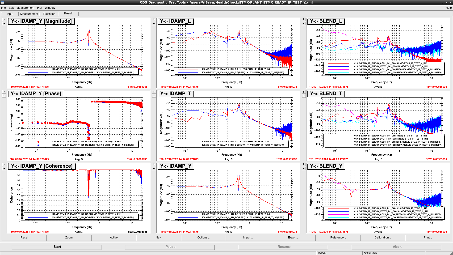
IM EULER DoFs measurements have different results from the reference but they are probably due to the sensor decoupling matrix modifications because there is no difference in TFs from each actuator to each sensor.
TM H1 gain is smaller than the reference by 3dB but I could not confirm the reason and it might be a hardware problem, so it is necessary to check.

Note:

TM health check template didn't work well because we installed switching circuit of ETMX TM coil drivers.
So, I modified the template and then it works well.

Images attached to this report
Comments to this report:
takaaki.yokozawa - 7:47 Thursday 08 October 2026 (37627) Print this report
I just put the results of the health check ETMX Tower part.
Images attached to this comment
takafumi.ushiba - 10:52 Thursday 08 October 2026 (37629) Print this report

This log shows the health check results of ETMX tower.
I picked up several graphs, which needs to be discussed here, so please see klog37627 to check all transfer functions.

Summary:

Peaks around 1Hz has strange shape when exciting F0 and F1.
BF GAS transfer functions have lower gain than the reference.

Detail:

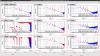
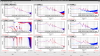
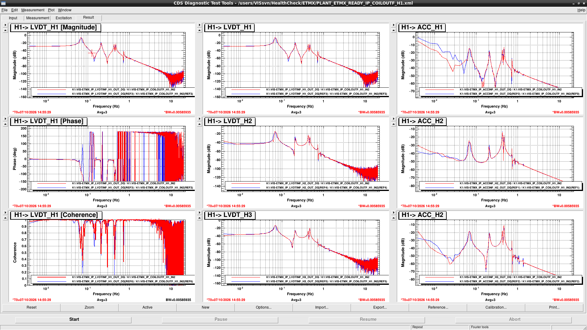
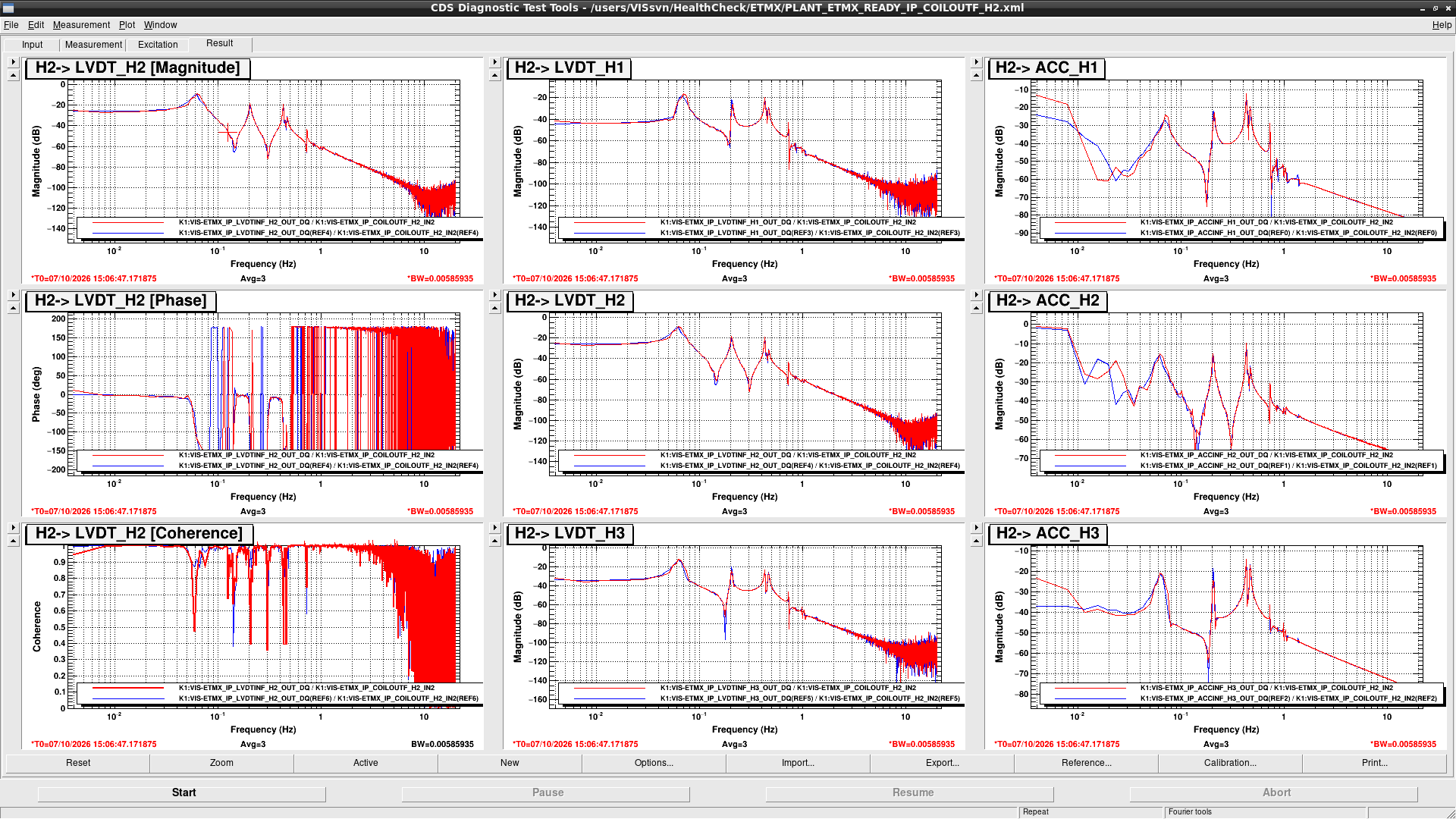
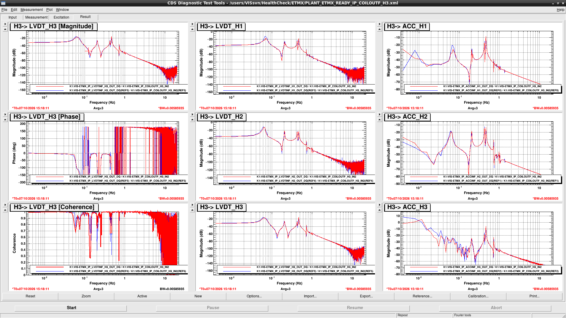
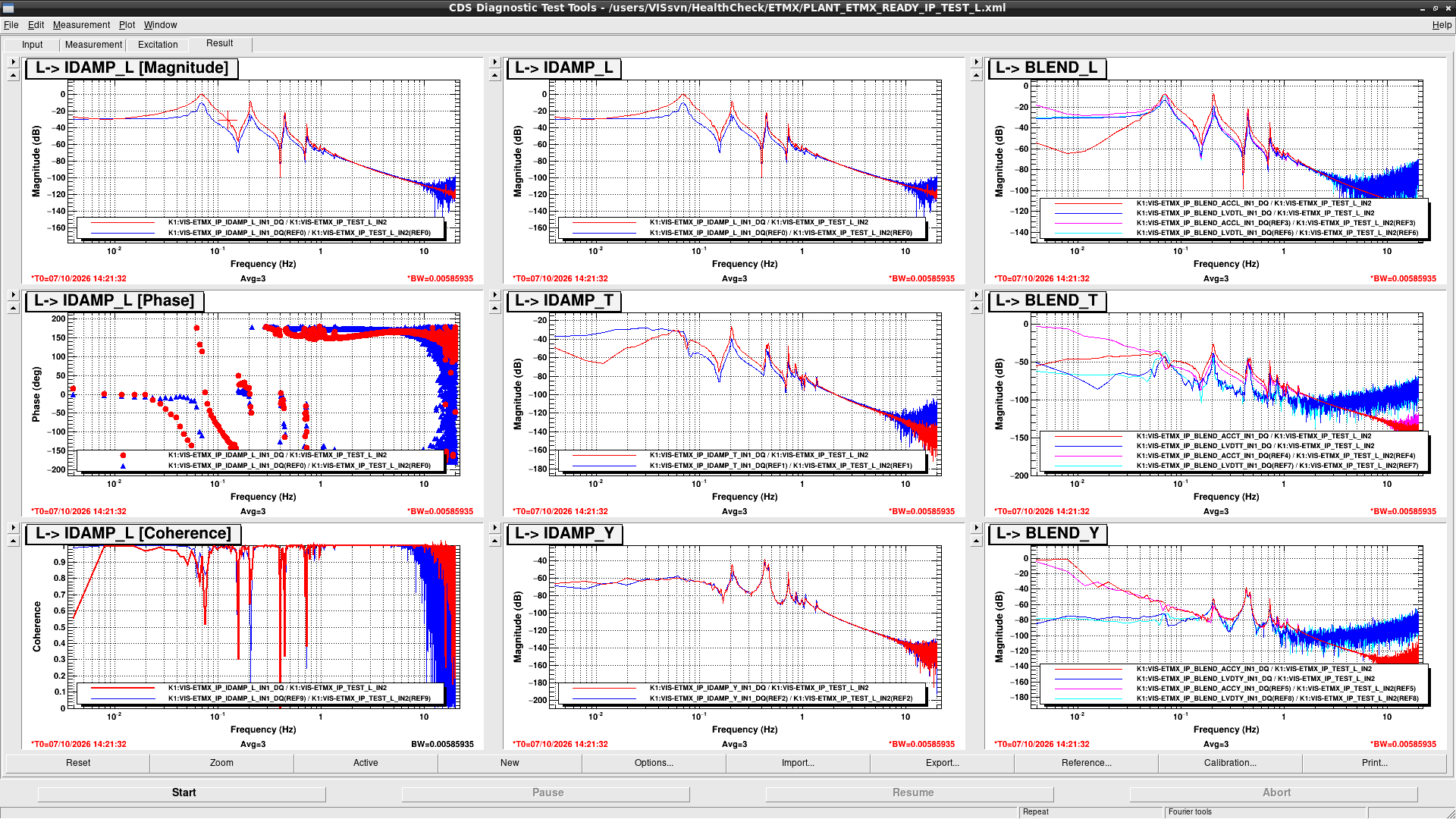
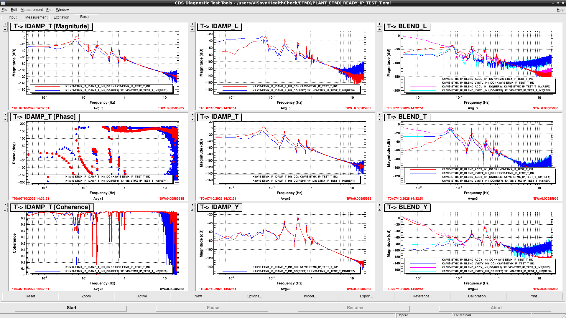
IPL and IPT transfer functions (fig1 and fig2) are different from the reference but these are due to the filter setting changes due to the FLDACC controls.
Figure 3 and 4 show the transfer functions when changing the filter setting.
Though there are still difference at 30mHz and peaks around 70mHz, they should be fine in terms of the health check because they are due to crossover between ACC and LVDT and coupling between L and T, respectively.

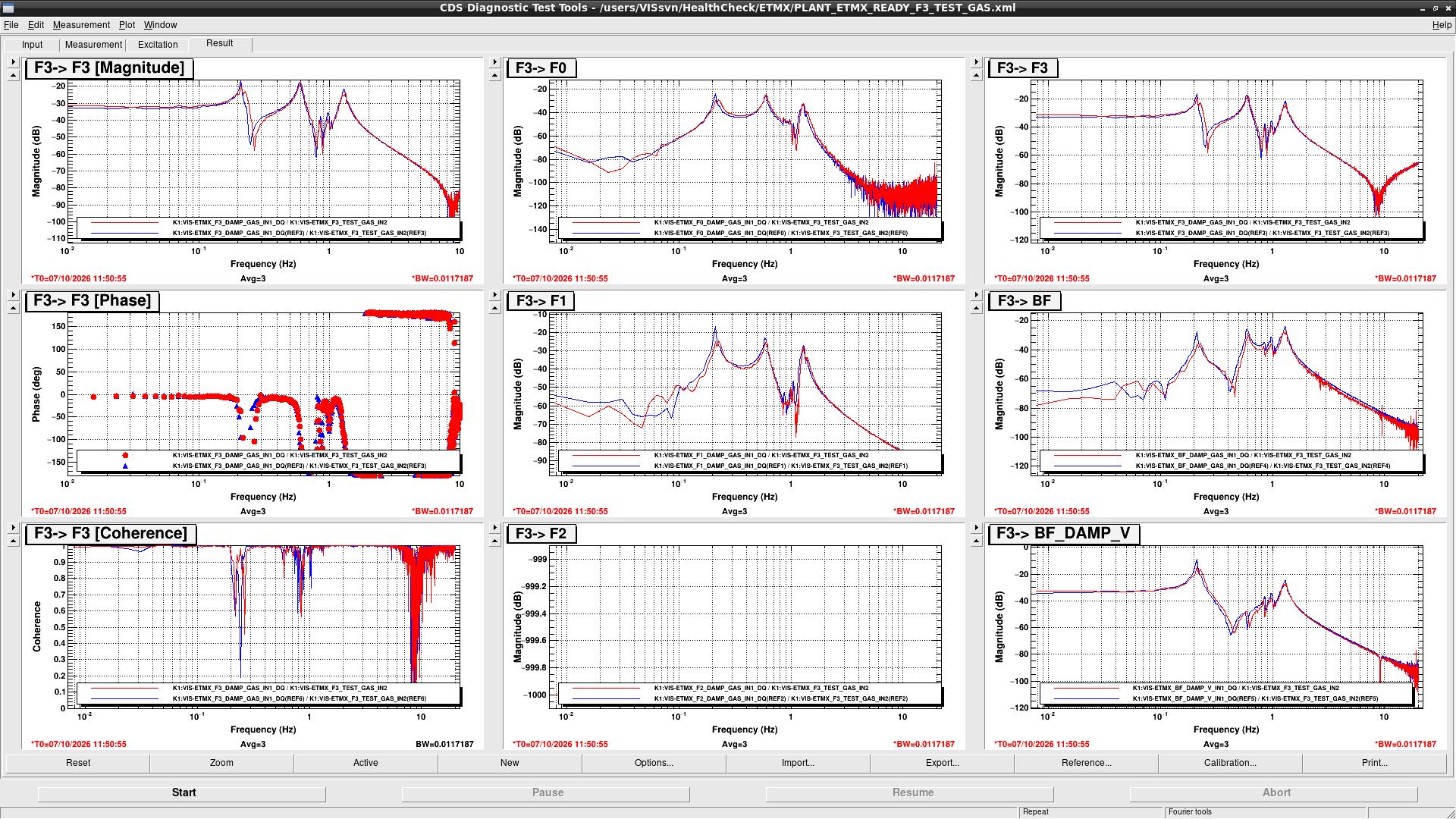
F0 and F1 transfer functions (fig5 and 6) are also different from the reference at the peaks around 1Hz.
According to Takahashi-san, the current suspension position is close to touching the outer flame, and large excitation could cause the suspensions to touch the flame.
So, I measured F0 GAS TF with 10 times smaller excitation (fig7) but the situation didn't change.
In addition, I checked suspension was touching somewhere by moving F1 GAS filters (fig8).
Since there is no motion at F3 and BF GAS, suspension doesn't seem to touch the outer flame.
However, F0 GAS has a strange behaviour due to the change of the F1 GAS filter position, so it is necessary to identify what happens.

BF GAS transfer function has lower gains than the reference at entire frequency bands.
Since the gain at high frequency (frequency region where suspension acts as the free mass) is low, it cannot be explained by just changing the stiffness of the GAS filter.
Since suspension doesn't seem to touch, LVDT calibration and/or actuator efficiency might be reduced.

Other than those differences, TFs are well matched with the references, so they should be fine.

Note:

About IPL and IPT transfer function, manual treatment is now necessary for measuring the TF with correct filter setting.
I will implement it into automeasurement script later but until then, please turn on FM8 of K1:VIS-ETMX_IP_FLDACCINF_H{1,2,3} and FM1 of K1:VIS-ETMX_IP_ACCBLEND_FLDACC{L,T} before starting the script and turn them off after the measurement.

Images attached to this comment
takafumi.ushiba - 14:37 Thursday 08 October 2026 (37630) Print this report

I checked the F0 GAS TF when suspension is TWR_FLOAT state but no significant change happens (fig1).
Also, I checked the F0 GAS motion when moving F1 GAS filters and confirmed F0 GAS also moved (fig2).
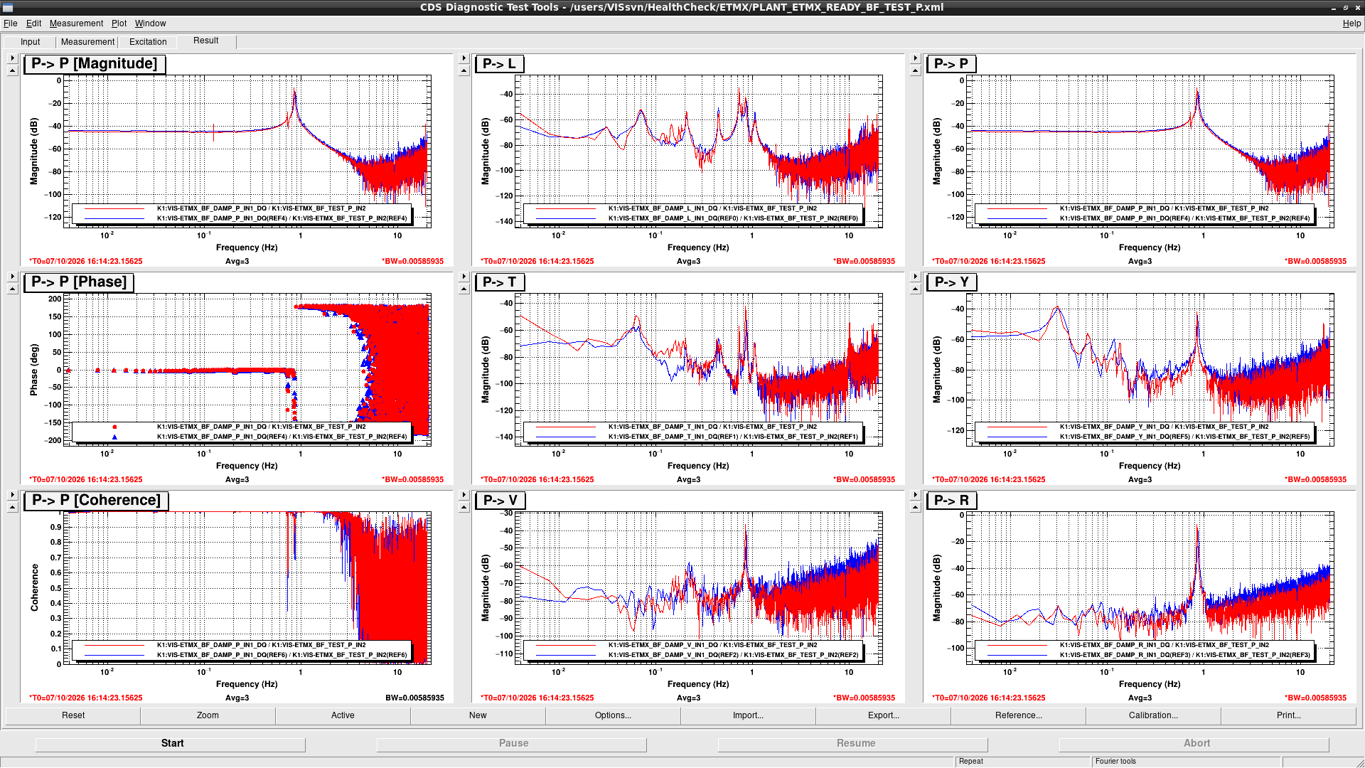
So, the situation could not be recovered by just moving BF yaw position.

Images attached to this comment
takafumi.ushiba - 12:26 Friday 09 October 2026 (37636) Print this report

[Uchiyama, Ushiba(remote)]

Summary:

We performed the swapping test of ETMX TM H1/H2 actuators and confirmed the problem is at the outside of the chamber.

Detail:

We performed the swapping test of ETMX TM H1/H2 actuators.
As usual, excitation was injected at 10Hz and we measured TF from excitation signals to TM OpLev PIT.
Figure 1 shows the results.

Left and right pannels show the results when H1 and H2 coil were actuated.
Blue and red represent the measurement before and after cable swapping.
Black line in the left pannels show the reference measured in 2024.

For H1 actuator, red line is higher than blue line by 3dB and comparable with black line, which means actuator efficiency was recovered by swapping the cable.
For H2 actuator, red line is lower than blue line by 3dB, which means actuator efficiency was removed by swapping the cable.
Therefore, we can conclude that the source of actuator efficiency reduction is not at the inside of chamber but at the outside.
Though we haven't confirmed which circuit has a problem, we don't have to reopen the chamber and check the suspension.

Images attached to this comment
ryutaro.takahashi - 13:10 Friday 09 October 2026 (37637) Print this report

Uchiyama-san checked the LVDT-ACT coil resistances for the BF GAS. They did not change much.

Pin Reference [Ω] This time [Ω]
1-6 217.7 229.6
2-7 95.6 95.6
3-8 129 128.9


Search Help
×

Warning

×