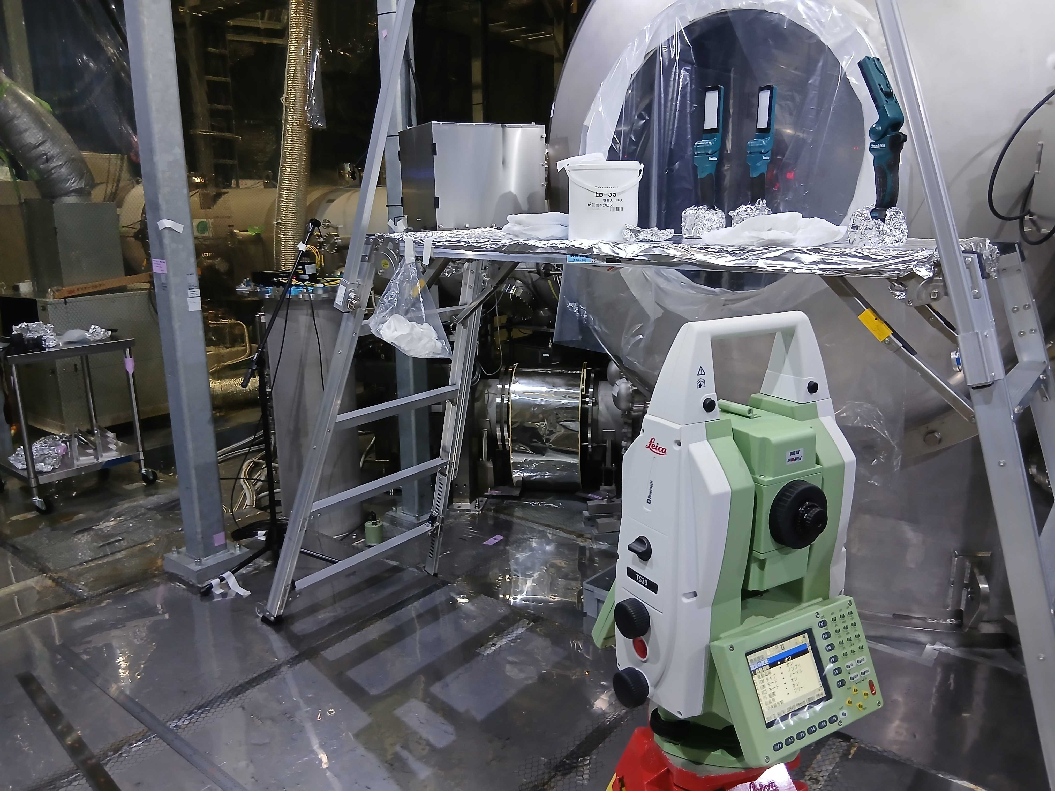
In preparation for the triangulation survey, we brought the total station to the site and carried out setup and assembly work.
A detailed work log will be added later.
Preparation for the ETMX Position Survey
Background and purpose
In the NCal calibration, the uncertainty in the center-to-center distance between the NCal and the test mass is one of the major contributors to the overall uncertainty of the NCal signal.
Therefore, while the ETMX chamber is open, it is important to directly survey reference points near the test mass and thereby reduce the uncertainty in the test-mass center position compared with an estimate based only on design drawings and manufacturing tolerances.
Prior to the actual ETMX survey, the surveying instruments were brought to the X-end, and the instrument setup and basic surveying procedure were tested. In particular, an object with a known length was measured to verify the procedure for reconstructing the distance between two points from the measured horizontal angles, vertical angles, and slope distances.
Survey preparation
A Leica T30 total station was brought to the X-end and assembled for the survey.
The horizontal-angle convention of the T30 was confirmed to be Horizontal Right (HR), meaning that the horizontal angle increases clockwise when viewed from above.
A KEK sticker attached to the wall was also sighted and measured to confirm that targets on the wall can be observed with the total station under the conditions expected for the actual survey.
As a basic check of the surveying procedure, both ends of a 1500 mm reference scale were measured. The horizontal angle, vertical angle, and slope distance to each endpoint were recorded, and the three-dimensional distance between the two endpoints was calculated from these measurements.
Check of the electronic level
The T30 has a built-in two-axis electronic level, with the two axes displayed as the L and T axes.
Initially, after leveling the instrument such that the electronic-level readings were close to 0°, the total station was rotated horizontally by 180°. A change in the electronic-level readings was observed after the rotation, with a maximum difference of approximately 0.1°.
This indicated that the electronic level had a zero-point offset.
Based on the 180° reversal measurement, the offsets were estimated to correspond to reference readings of 0.0008° for the L axis and 0.0091° for the T axis. The instrument was then leveled more carefully while taking these offsets into account.
After this adjustment, the total station was rotated again over a wide range of horizontal angles. The electronic-level readings remained nearly constant, with variations suppressed to approximately 0.001°. This confirmed that the instrument remained level as it was rotated.
As an independent check, a laser line level was also used to establish a horizontal reference. The telescope of the total station was rotated over a wide range of horizontal angles, and the projected laser line was observed at several positions located at approximately the same distance from the laser level. At these positions, the laser line was found to coincide closely with the center of the telescope field of view.
The agreement between the laser reference and the telescope line of sight over a wide horizontal-angle range provides an additional confirmation that the total station was properly leveled.
Measurement of the 1500 mm reference scale
The horizontal angle, vertical angle, and slope distance were measured for both ends of the 1500 mm reference scale. The distance between the two endpoints was then reconstructed from these measurements.
The calculated distance was 1502 mm, corresponding to a difference of 2 mm from the nominal length of 1500 mm.
Since this measurement was intended as a preliminary check of the instrument setup and surveying procedure, this result alone does not demonstrate a surveying accuracy of 2 mm. However, it confirms that the overall procedure for reconstructing the three-dimensional distance between two measured points from the angular and distance measurements is functioning as expected.


ETMX Position Survey — Day 1
Detailed measurement data and survey results will be added tomorrow or later.
Today, 5 October, we carried out the first day of the ETMX position survey using a Leica T30 total station, following the preparation described in [klog 37607](https://klog.icrr.u-tokyo.ac.jp/osl/?r=37607).
We plan to take measurements from at least two locations. Today, we completed the measurements from one location.
The following target points were observed:
- Four corners on the near side of the sapphire nail heads, as viewed through the chamber opening.
- Four edge points on the copper clamps securing the nail heads.
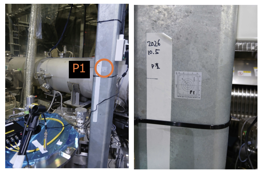
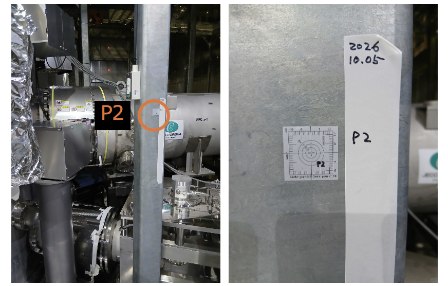
- Two reference markers attached to pillars outside the chamber, within the clean booth at the X-end.
We also measured the marker for another measurement location to establish a baseline for the triangulation survey.
ETMX Triangulation Survey — Day 2
A detailed report on the triangulation survey will be added later.
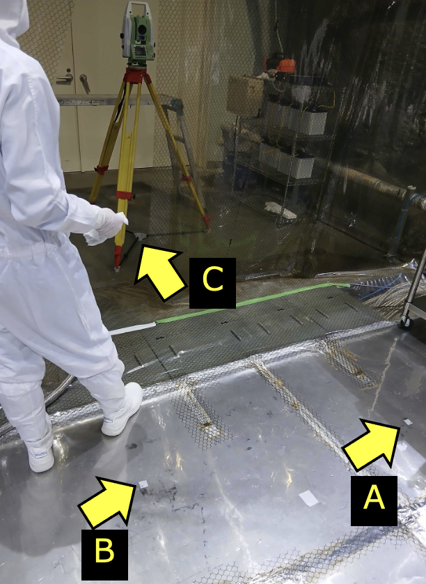
Following the preparation described in [klog 37607](https://klog.icrr.u-tokyo.ac.jp/osl/?r=37607), we carried out a triangulation survey at the X-end using a total station placed at three locations: A, B, and C.
The following points were observed from these three locations for triangulation:
- Reference markers P1 and P2.
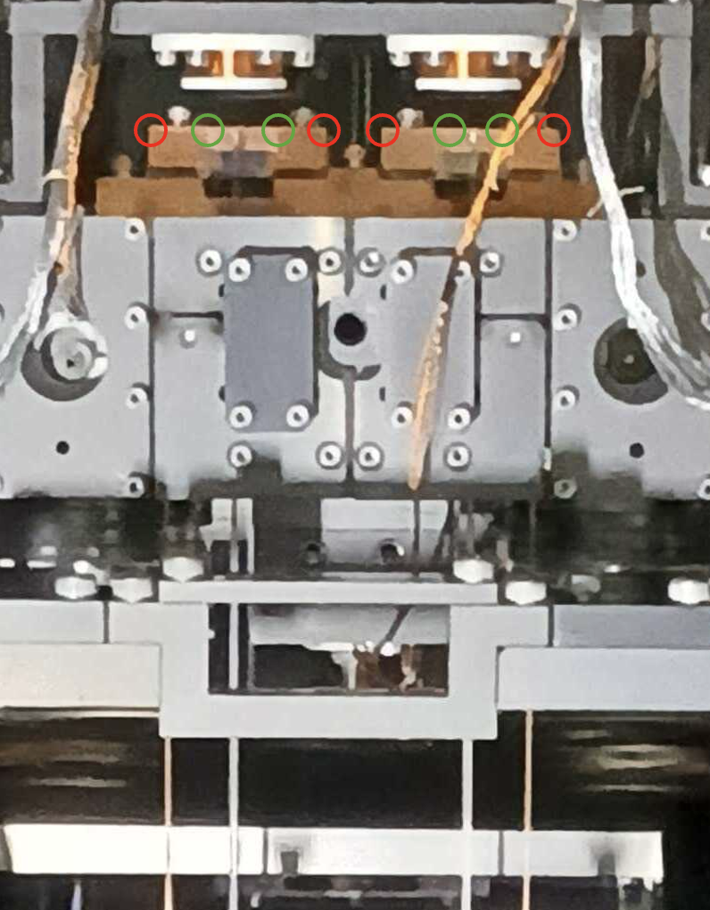
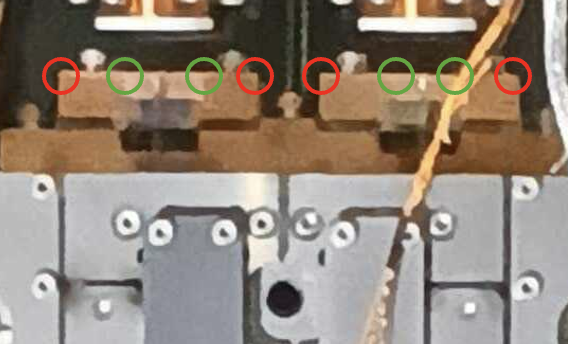
- Four corners of the copper housing, circled in red and named C1–C4.
- Four corners of the sapphire nail heads, circled in green and named S1–S4.
In addition, the following points were measured from location C only:
- The HR-side corner of the test-mass ear.
- The HR-side upper corner of the AR-side sapphire nail head bonded to the ear.
Supplements
We aligned the horizontal line of a green laser level with the top surface of the sapphire nail head and made a best-effort adjustment to align it with the center of the P1 marker.