Reports 1-1 of 1 Clear search Modify search
DGS (General)
takafumi.ushiba - 13:09 Thursday 24 September 2026 (37524) Print this report
-18V power suply for MCF rack has some problems

[Dan, Ushiba]

Abstract:

We found that -18V power supply for IMC0/MCF0 racks is turned off now.
To avoid supplying only +18V to the circuits, we turned off all circuits inside IMC0/MCF0 racks except for IO chassis.
Since we are not so sure the reason why -18V power supply is turned off, we take over the work to DGS subsystem.

Detail:

To recover the MC suspensions, I checked OpLev signals of MC suspensions and found that all of them had no signal.
Since actuator range of the Type-C suspension is small and it is difficult to go out of the OpLev range, it is likely a problem of the light sources and/or QPDs.
So, we we entered the mine and check the status of MCF0 rack.

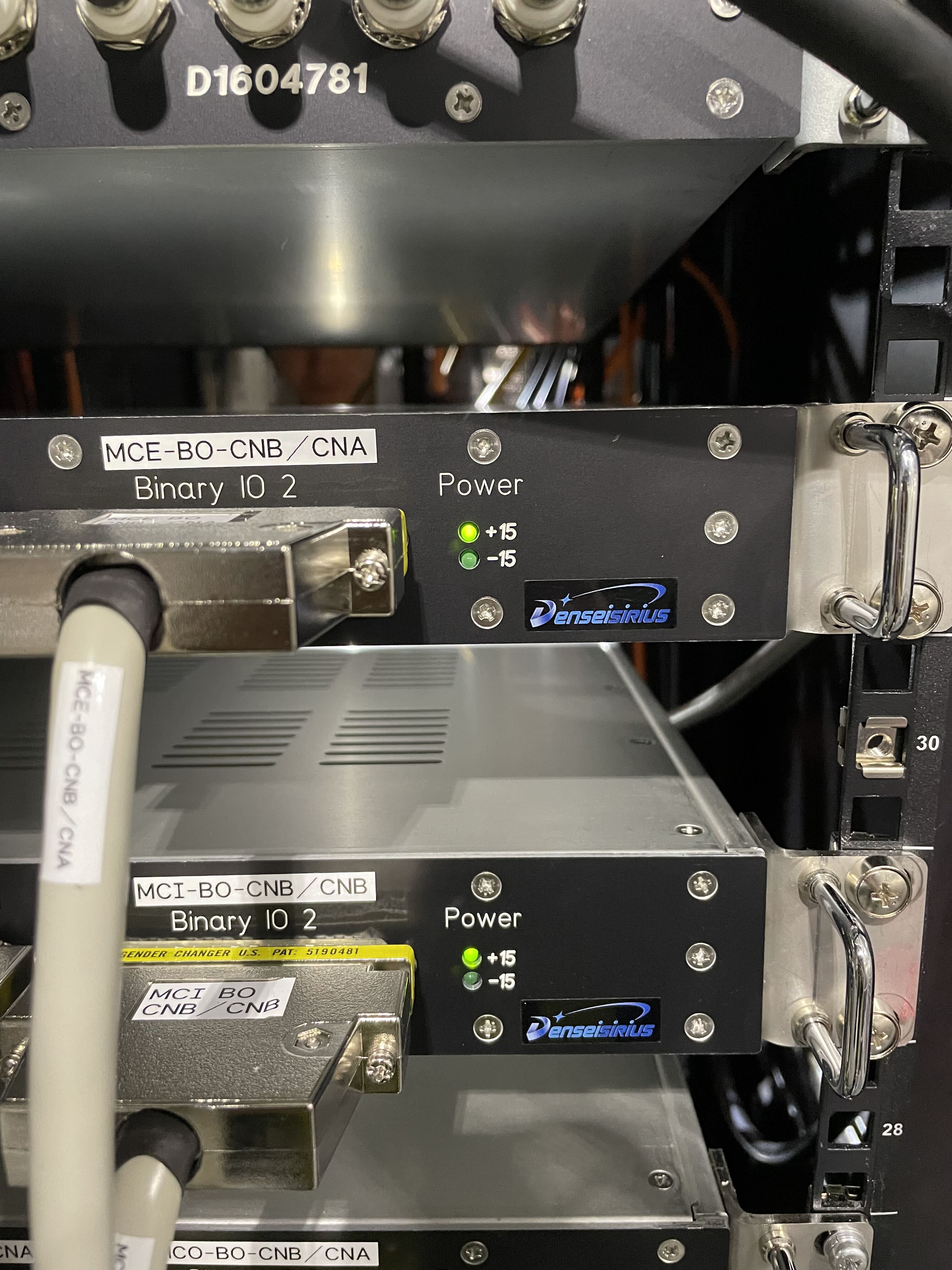
When we checked the MCF0 rack, we found that the -15V indicator doesn't turn ON (fig1), which means -15V is not properly supplied to the circuit.
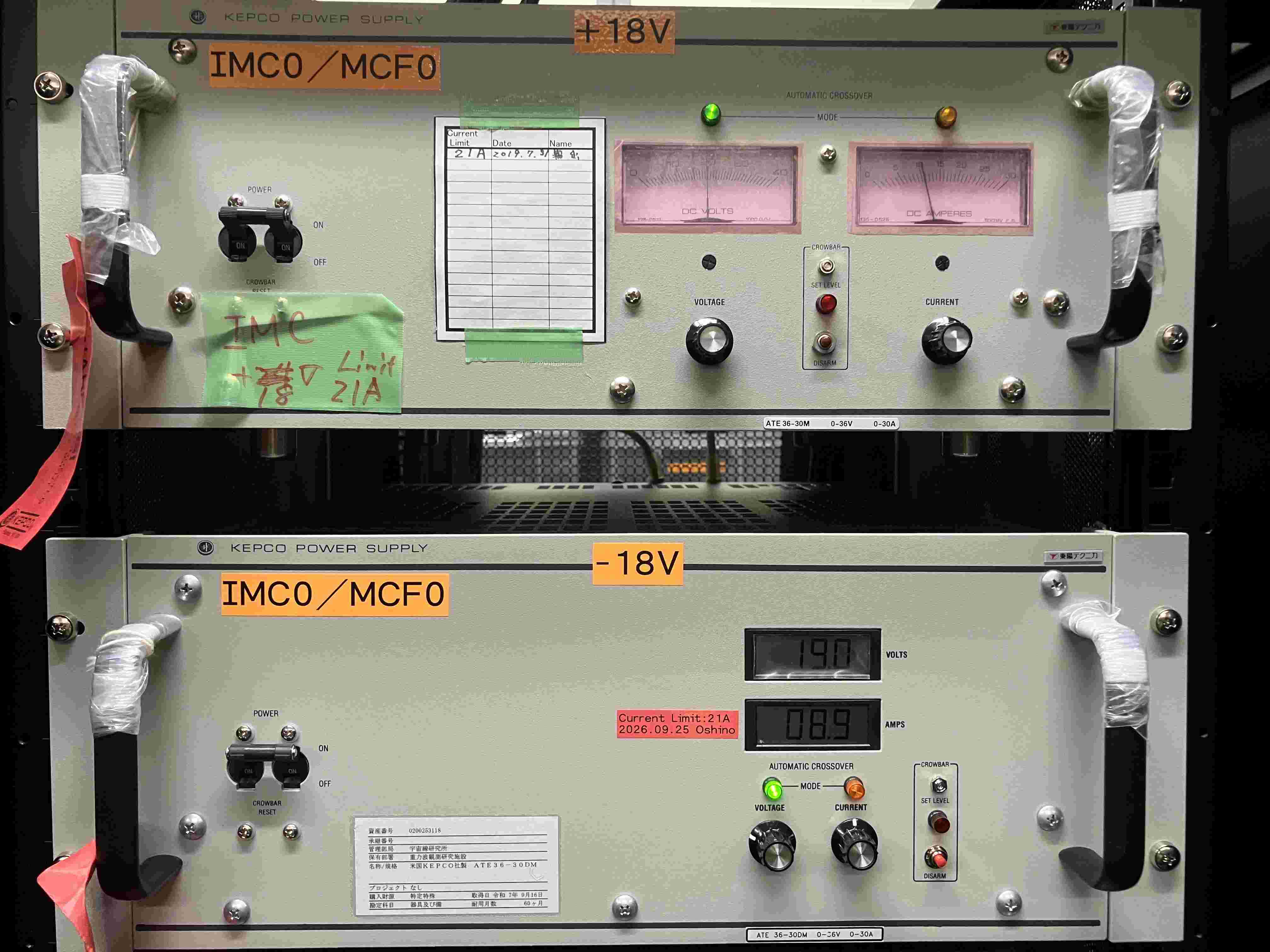
Then, we checked the power supply inside the computer room in the mine and confirmed the -18V DC power supply is turned off (fig2).
According to Dan Chen, he (and Washimi-kun, Ikeda-san) turned on it and checked the supply voltage at the rack and they found no issue at that time.
So, it might be breakage f the power supply itself and we take over the recovery work to the DGS subsystem.

Since it is not good to supply only +18V to the circuits, we turned off all circuits except for IO chassis at MCF0/IMC0 racks.

Images attached to this report
Comments to this report:
shoichi.oshino - 15:50 Thursday 24 September 2026 (37528) Print this report
[Aoumi, Moriwaki, Shimode, Oshino]

We investigated the power supply. The rack breaker was first turned OFF, and the -18 V power supply was turned ON. We confirmed that both +18 V and -18 V were present upstream of the breaker.
 
The breaker was then turned ON, and the AEL circuits were powered up one by one while monitoring the supply voltage. The supply voltage decreased by approximately 0.05 V for each additional circuit. No circuit showed signs of an obvious fault or excessive current draw.
 
The KEPCO power supply current was also checked. The current limit was set to 21 A, while the measured load current was approximately 9-10 A, well below the limit.
After all circuits had been restored, the power supply status was monitored for approximately 30 minutes. No significant changes in voltage or current were observed during this period.
 
Based on these observations, no evidence of a short circuit or excessive load was found during the inspection.
Images attached to this comment
shoichi.oshino - 11:53 Friday 25 September 2026 (37534) Print this report
[Sawada, Takahashi, Yamaguchi, Oshino]

Following the stop of the -18V power supply found on 9/24 (klog 37524, 37528), we replaced the -18V KEPCO power supply for the IMC0/MCF0 racks with a new unit this morning.

- It has not been determined whether the problem is on the power supply side or on the circuit side. A faulty supply could damage the circuits, and a faulty circuit could damage a healthy supply.
- The supply had already fall once during the recovery work over the holidays, so it could fail again even if it looks fine now.
- IMC0 has more whitening filters installed than we have spares. We therefore judged that damaging the circuits with a faulty supply is the more serious risk.

[Procedure] (9/25)
1. Turned off all circuits.
2. Turned off the breakers on top of the rack.
3. Turned off both power supplies.
4. Replaced the -18V supply.
5. Turned the supply on and set it to 19 V, current limit 21 A (7 turns).
6. Confirmed 19 V at the output with a tester.
7. Turned on the rack breakers. At this point both +/- read 19 V.
8. Turned on the circuits one by one.
9. Final voltages at the rack-top breakers: +18 V, -18.4 V.
10. Monitored for 30 min. No problems found.
Images attached to this comment
takafumi.ushiba - 14:47 Friday 25 September 2026 (37532) Print this report

I checked the time series of OpLev signals (fig1).

The data region (t~-4d) is the time before power outage.
No data region (t~-3d) is probably the time during the downtime of data taking.

After the recovery of DGS, the signals are zeros for all segments, which should be the time before restarting DGS (the data seems completely zeros).
At the left cursor, the signals went negative for al segments and sum.
I'm not so sure but it seems the time when turning on the DGS for IMC0.

Since the output of SEG*_OUT and OPLEV_SUM went negative, the signals seem already starange at that time.
So, there are two possibilities:
1. MC OpLev signals was not properly recovered during the recovery from the power outage.
2. Once recovery was succeeded but -18V was turned off somehow before recovering DGS.

I have no idea how to confirm which scinario is correct but probably scinario #2 is preferable based on the discussion between recovery workers.
So, it is likely that the power supply and/or circuits have some problems.

Images attached to this comment
Search Help
×

Warning

×