[Lucia, Maria, Diego, Keiko, Yuta]
We measured angular actuation transfer function of each coil for each IMC suspension.
As a result, we found that the coil driver for the MCi is broken (will be reported later).
MCo pitch actuation is strange below 10 Hz, which suggests something is wrong in the intermediate mass.
MCe looks OK, but the measured transfer function is ~1.5 times smaller than the model in free mass region.
Signs of actuation matrix for MCo and MCe look OK.
What we did:
1. Measured transfer fuctions from actuation from a coil K1:VIS-MC(I|O|E)_TM_COILOUTF_H(1|2|3|4)_EXC to oplev signals K1:VIS-MC(I|O|E)_TM_OPLEV_(PIT|YAW)_OUT. We kept the K1:VIS-MC(I|O|E)_TM_COILOUTF_H(1|2|3|4)_GAIN to be as it is.
2. Compared the result with the similar measurement using all 4 coils (klog #3724) to check the signs of the actuation matrix.
Result for MCi:
We could see actuation from H4, but couldn't see any actuation for H1,H2,H3. Keiko and Lucia looked into the cabling and the coil driver and found that the coil driver is broken.
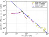
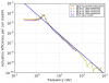
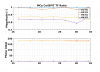
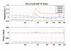
Result for MCo:
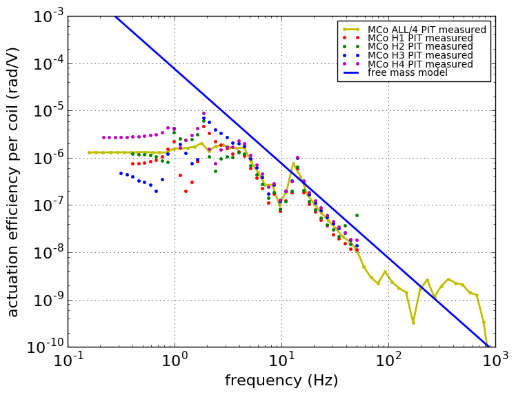
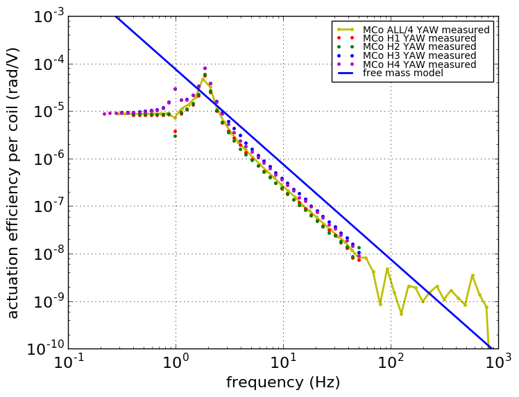
See attached. Red, Green, Blue, Magenta dots are measured angular actuation TF from H1, H2, H3, H4. Yellow dots with line is the measured angular actuation TF using all coils divided by 4. Their levels are almost the same, which means that the signs of the actuation matrix is correct.
For pitch, actuation TFs are messed up below 10 Hz, which is consistent with DC response mystery (klog #3295, #3600, #3611). The peak at 13 Hz comes from the mirror stage, and funny behavior below 10 Hz suggests something is wrong in the intermediate mass. I think IM is touching the damping mass in a way that disturbs pitch motion but not yaw motion.
For yaw, H3 and H4 have larger efficiency than that of H1 and H2. There was a mystery that coil balancing work done at 20 Hz (klog #3170) and that at DC (klog #3295) did not match. Currently the coil balancing is done at DC, and you can see the discrepancy in balancing at free mass region. Considering the suggestion that IM is touching the damping mass, I think we should balance the coil at free mass region.
Also, the measured transfer function is ~2.5 times smaller than the free mass model (96 mm dia, 30 mm thick, 0.47 kg).
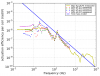
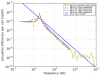
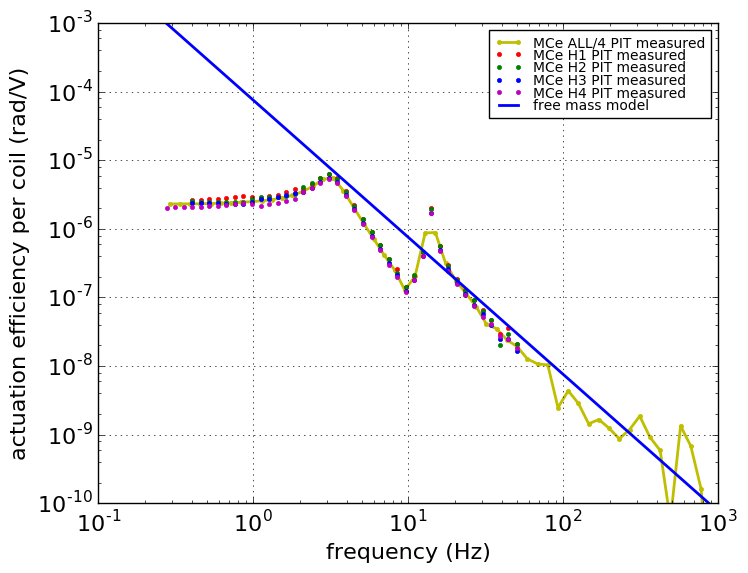
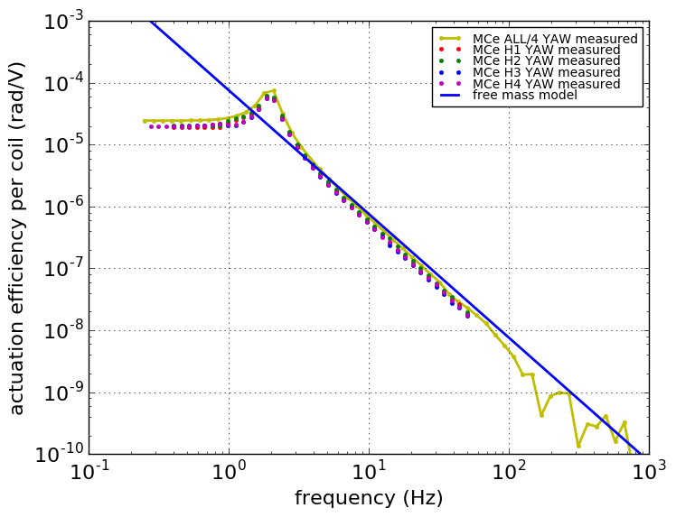
Result for MCe:
See attached. MCe looks a lot healthier than MCo. Still, the measured transfer function is ~1.5 times smaller than the free mass model.
Next:
1. We will use these transfer functions to re-tune the coil balancing.
2. Make a suspension model for the suspensions.
Moral of the story:
Please please characterize and compare measurements with expectations after installation......
[Diego, Yuta, Lucia, Maria, Keiko]
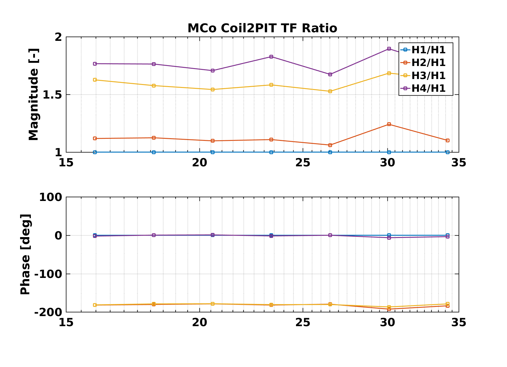
The measurements of the original report were used to recompute the coil balancing of the MCe and MCo mirrors:
- we decided to use the Free Mass Model range to compute the balancing factors, as in this range the response should be less influenced by the weird behaviour that was observed at the DC level for single coils;
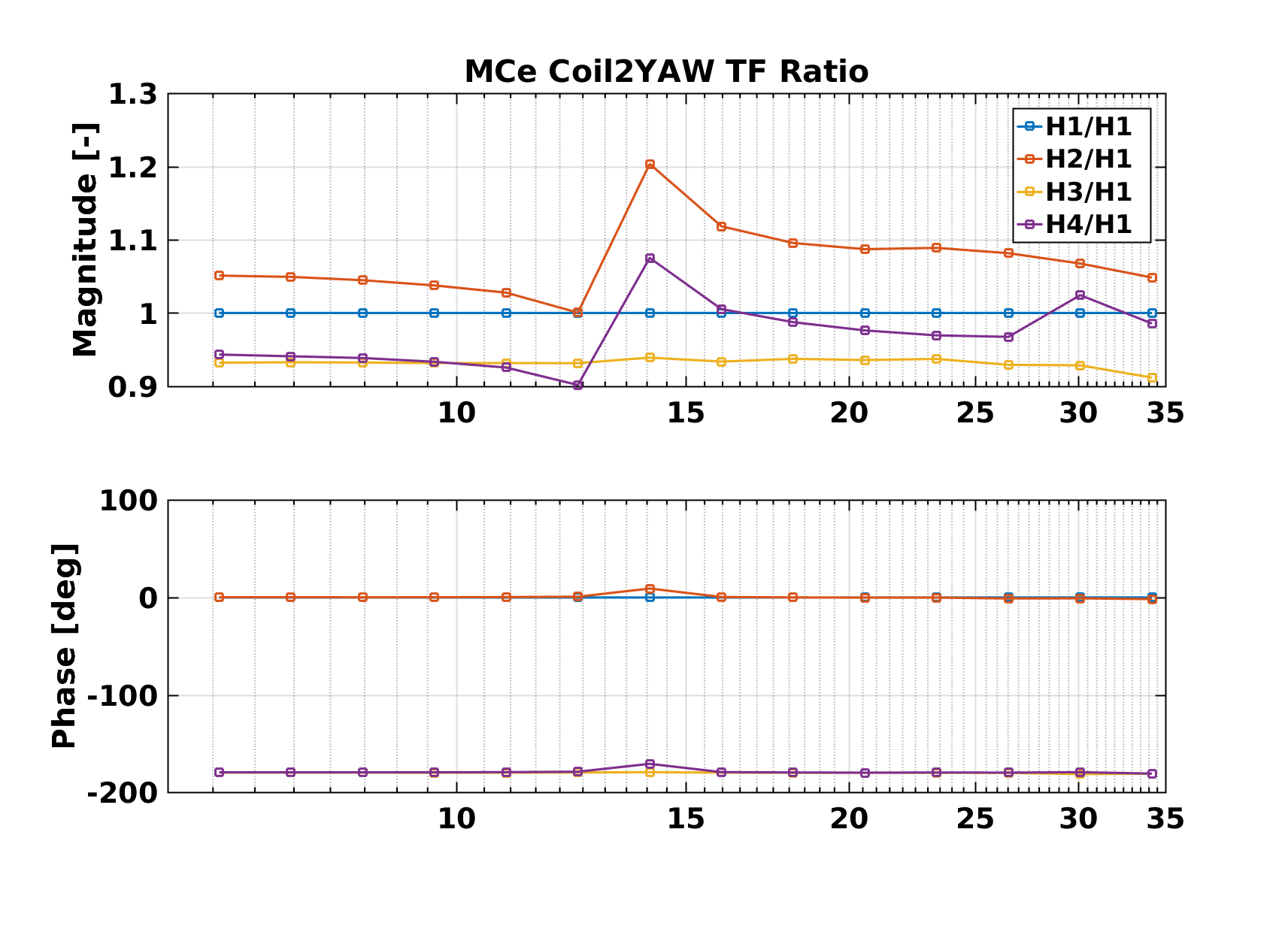
- we selected the 15-35 Hz range for PIT and the 5-35 Hz range for YAW, i.e. above the visible mechanical resonances and up to where we still got good coherence in the measurement;
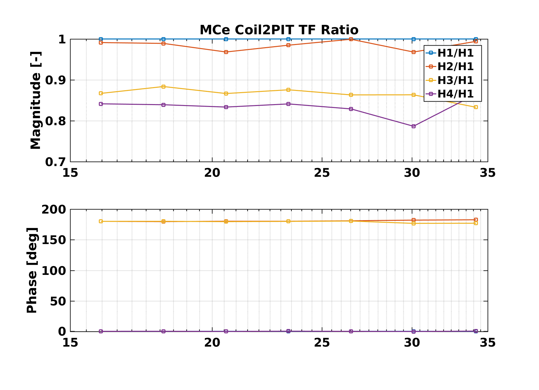
- initially we wanted to linearly fit such data in logaritmic scale, but after plotting the ratio between H(2|3|4) and H1 (see attached plots) we found out that such ratios are reasonably constant, so we decided to just take the average of the ratios instead;
- in the following tables there are the correction factors to the existing driving matrix elements, computed as the mean of the individual factors found for PIT and YAW;
- in the CommissiongWorkshop2017 Dropbox folder there are all the plots and the scripts, with the single ratios used to obtain the following values.
| H1 | 1.0 |
| H2 | 0.980 |
| H3 | 1.111 |
| H4 | 1.124 |
| H1 | 1.0 |
| H2 | 0.957 |
| H3 | 0.614 |
| H4 | 0.622 |

