Initial alignment for Xarm and Yarm performed.
I set the SR2 suspension to PAY_FLOAT state, ETMX, ETMY MISALIGNED state, ITMX MISALIGNED_BF state.
(single bounce from ITMY)
Close the GRX and GRY shutter.
I moved yaw direction using the IM optic align.
when I put the 10 count, the oplev yaw value moved 8 urad, so I roughly evaluated 10 count -> 8 urad in SR2.
the distance from SR2 to OMMT1 is 21,300 mm and we want to move the beam position on the OMMT1 at 50 mm, we need to move about 2.3 mrad in SR2 ~ 3,000 count to IMY optic align.
I added the +4,000 count, but we cannot see change in camera image, even I increased the IMC output from 1 W to 4 W, the situation was not changed.
and I changed to -4,000 count, but we cannot see change in camera image, I gave up this measurement today.
(OMMT2 trans QPD sum became almost zero even not moved so much)
Put the target inside the OMM chamber or increase the power to OMC (PRMI bright lock?)
With the PRX lock and this program, I will perform the similar measurement in next chance.

I set SR2 suspension to PAY_FLOAT state, requested PRX 1f lock to vertex guardian
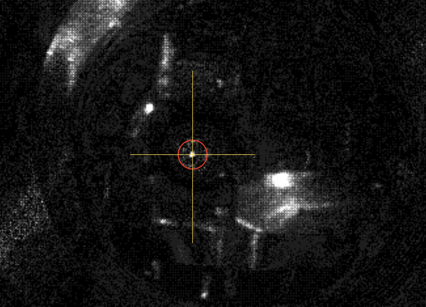
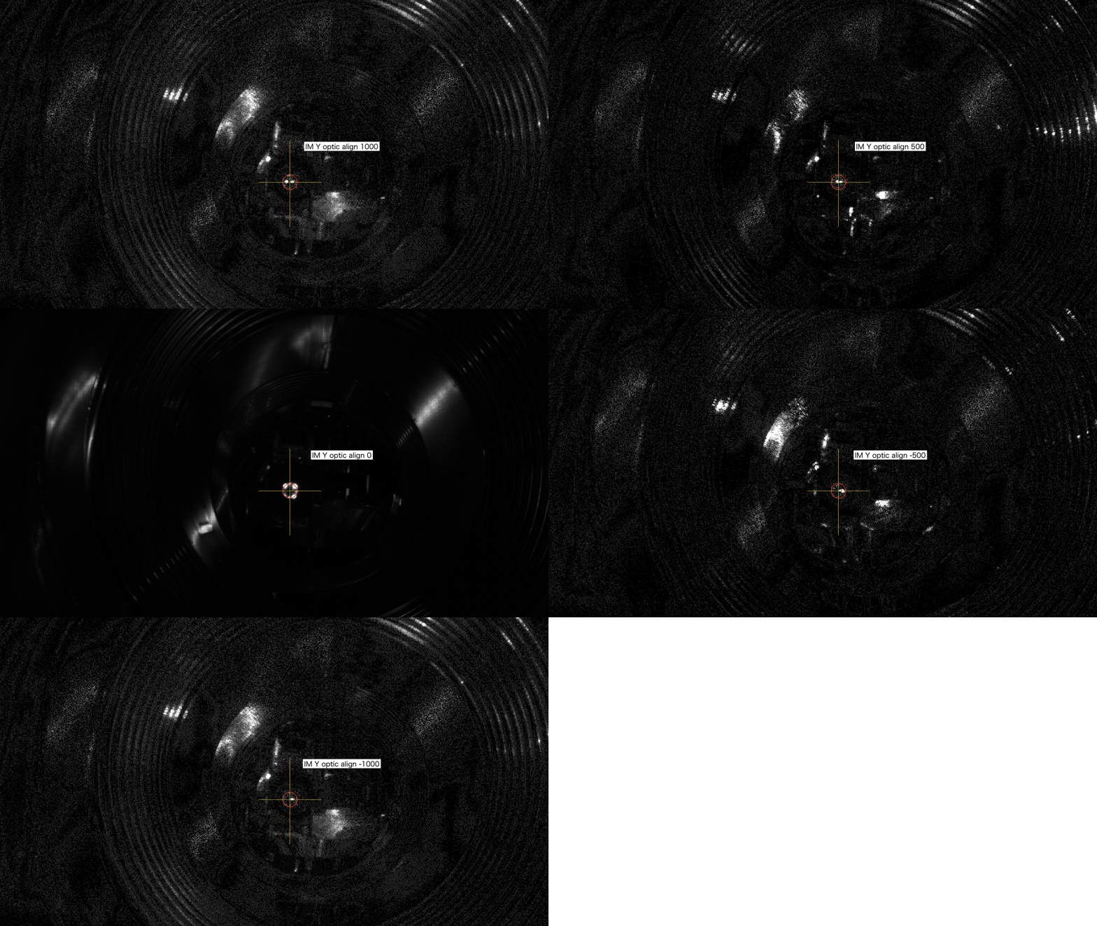
By the capture diff script, I can find the beam position on the OMMT1 mirror as shown in pdf1.
Original picture was the 0 -256 gray scale, and just performed the subtraction between two figures, and multiplied to 30 after performing the absolute.
From the circle image and center value of the +500 and 0 case, I found the 321 IM optic align value would be center.
Same measurement performed in pitch with adding 321 count IM optic align Y, I can obtain the 150 count would be center in pdf2.
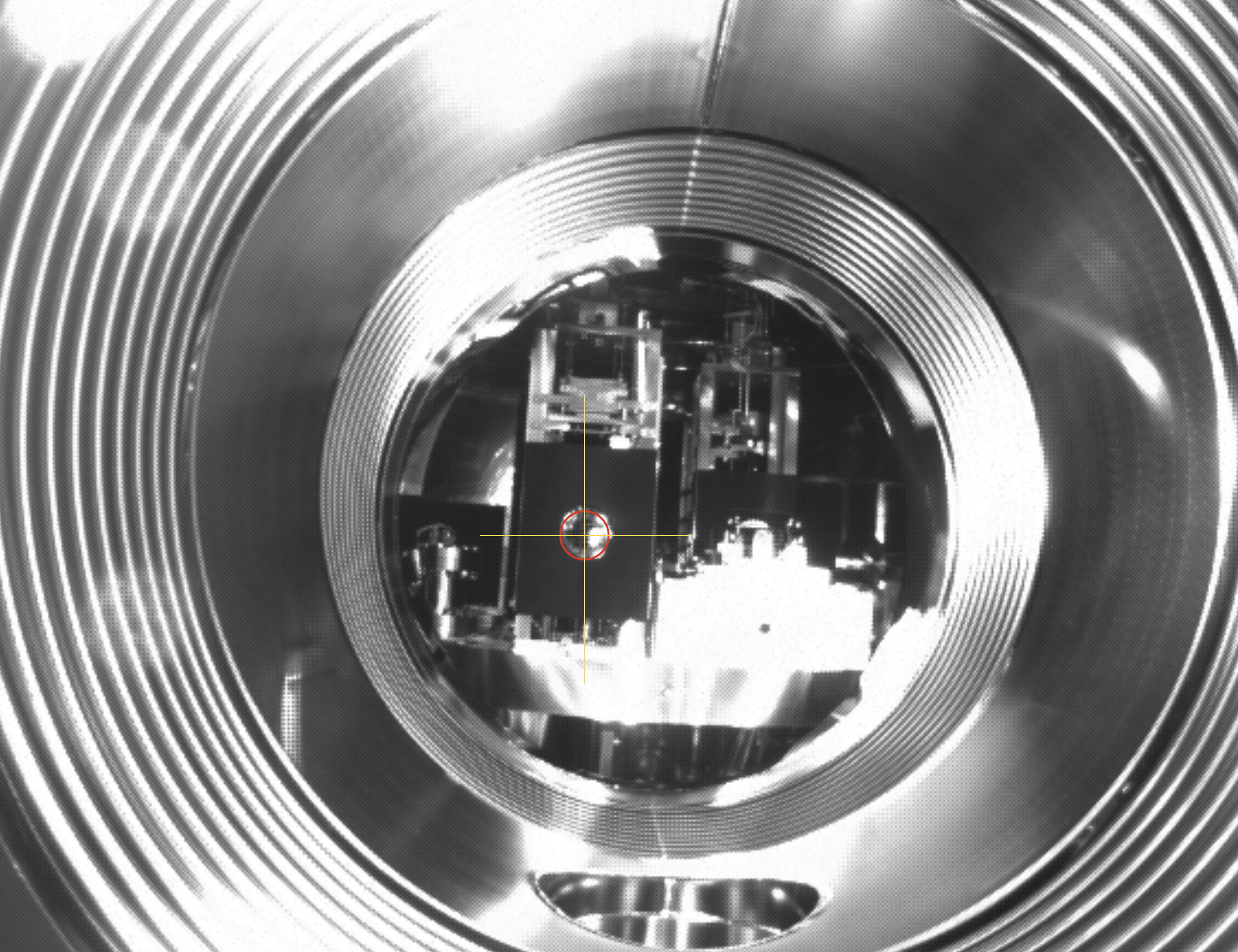
I took picture with PRX lock and without IR laser (shutter on), and confirmed the SR2 centering as shown in Fig.1.
Now, I didn't perform this change to SR2, It would be better with centering of SR2 oplev next Monday(?).


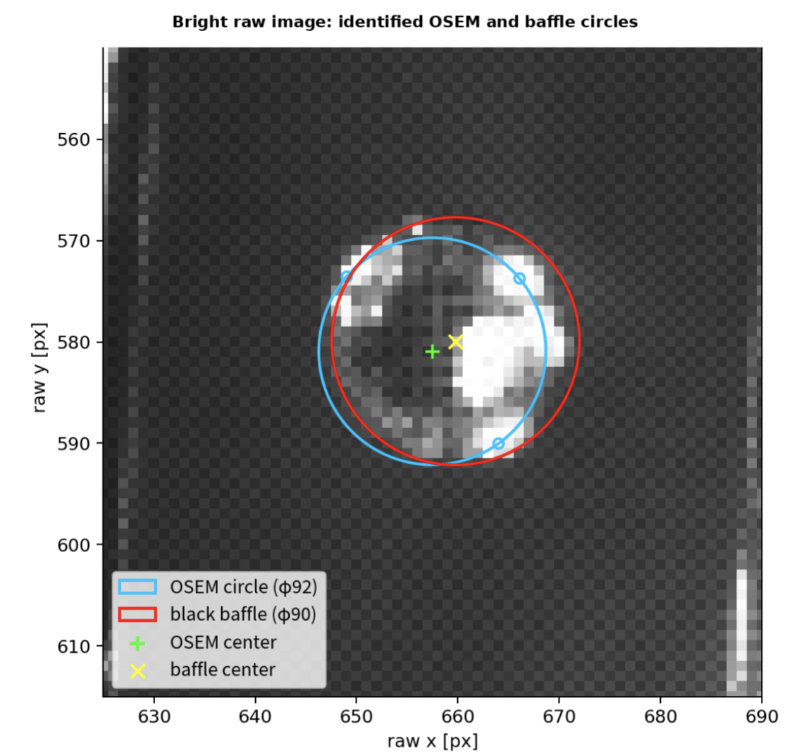
Red circle is the image of black cover in front of OMMT1, with yellow was the center.
In this figure, we put the TCam mirror below the IR beam, so horizontal would be OK, but we need investigation for vertical direction.
I attached the gif image.
Before that, I took picture with bright image.
Fig.1. showed the image with red circle and yellow lines.
As you can see, the red circle was slightly lower than the hole in front of the black shield, but this camera was placed blow the IR beam height, it was not so strange.
Rather, circle can follow the center of the OSEM lights, I think.

ChatGPT generated the pdf report placed in attached file.
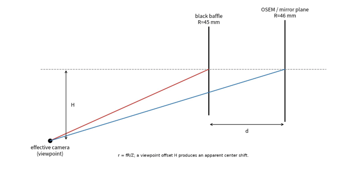
Image-plane separation
Yesterday, I checked angular of the jig to fix the camera, about 8 deg.
Camera vertical position about 90 mm from optical table OMM chamber
Fig.1. showed the Perspective projection model.
And from the calculation written in report, the camera image perspective projection would be consistent.
Fitting the black baffle circle and center of OMMT1 OSEM
black baffle circle, phi=90mm
OSEM circle phi=92mm
Fig.2. showed the fitting result, this result also used in image plane separation analysis
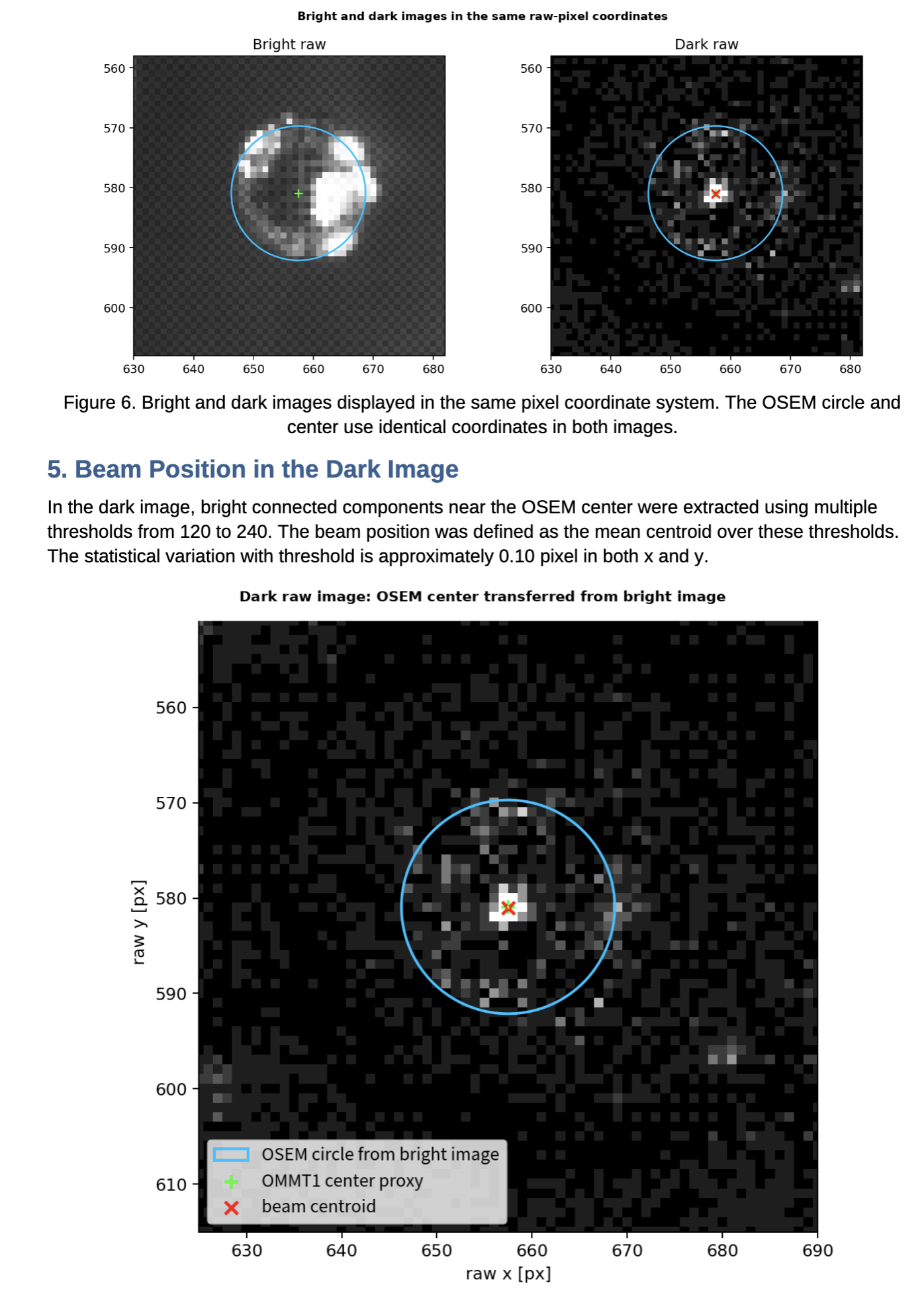
Consistency check of the IR beam on the OMMT1 mirror
As shown in Fig.3, the beam centroid is much consistent with teh OSEM circle from bright image.