[Fujimoto, Tanaka, Hirose]
Summary
We measured the WFS sensing matrix in the DRMI1f lock configuration. The SRM and BS ADS loops were turned off during the measurement.
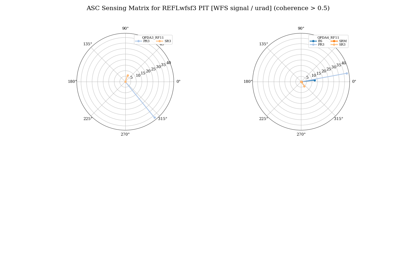
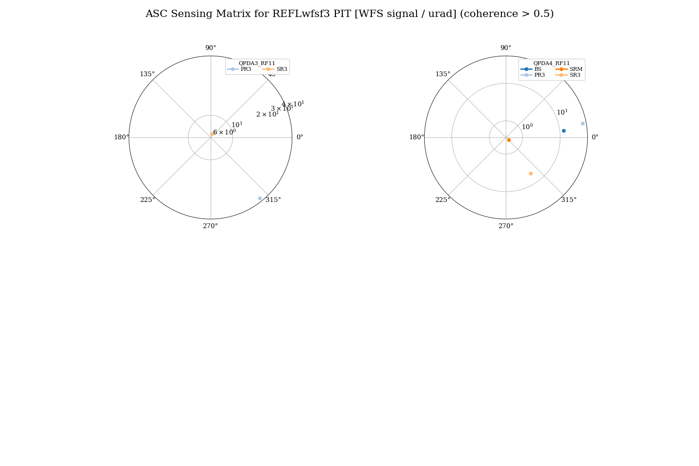
The DC centering loops were engaged for the WFS QPDs. However, the DC centering loop for REFL QPD3 PIT could not be engaged. We previously replaced and checked the PZT mirror mount, but there may still be a problem with the connection. Therefore, REFL QPD3 PIT was measured without the DC centering loop.
The sensing matrix was measured for all WFS QPDs using the PIT direction of BS, SRM, SR3, and PR3.
At first, each mirror was excited at 22.125 Hz. However, we found a phase shift of more than 50 degrees between the WFS signal and the OPLEV signal. This phase shift may come from the OPLEV low-pass filters and/or the whitening filters of the QPD signals. Since it was difficult to identify the sign for each degree of freedom, we repeated the measurement at a lower frequency of 2 Hz.
Result
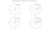
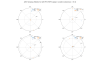
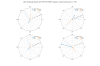
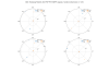
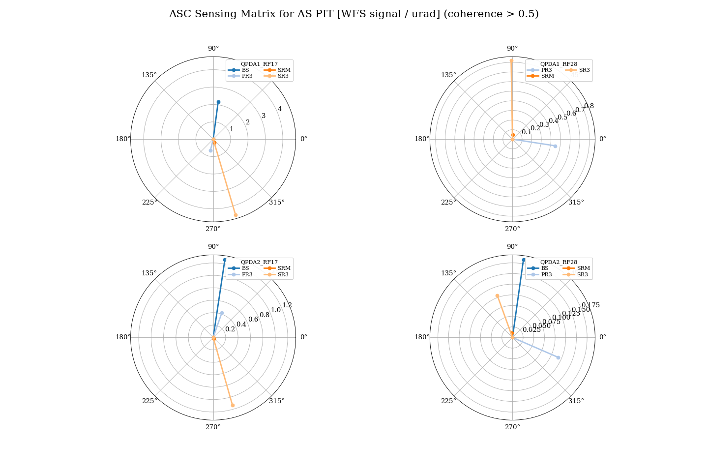
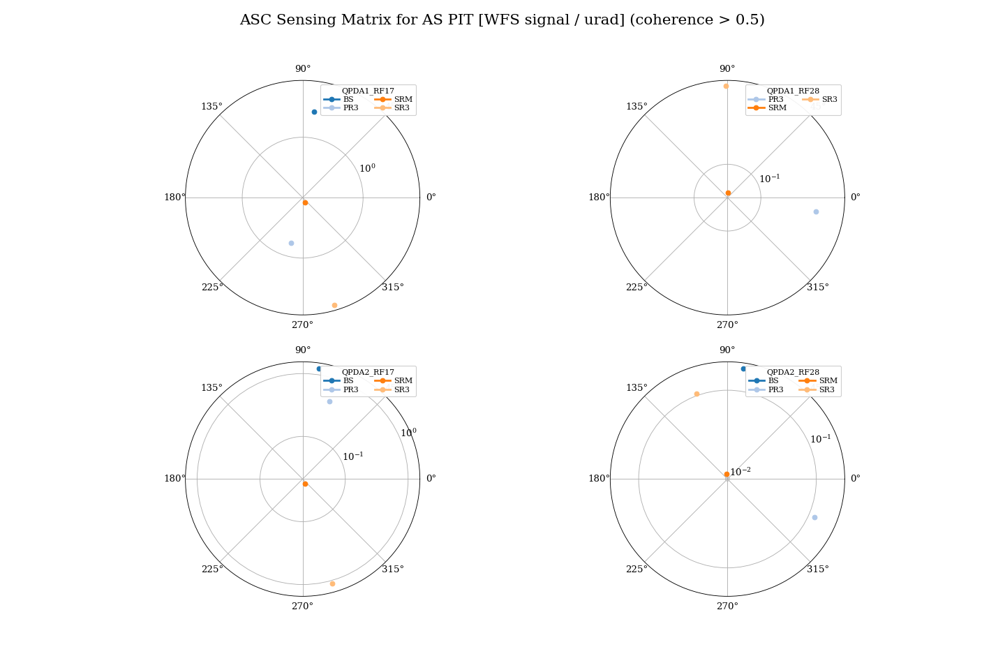
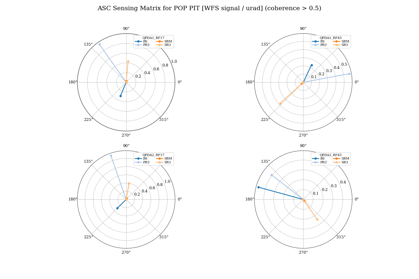
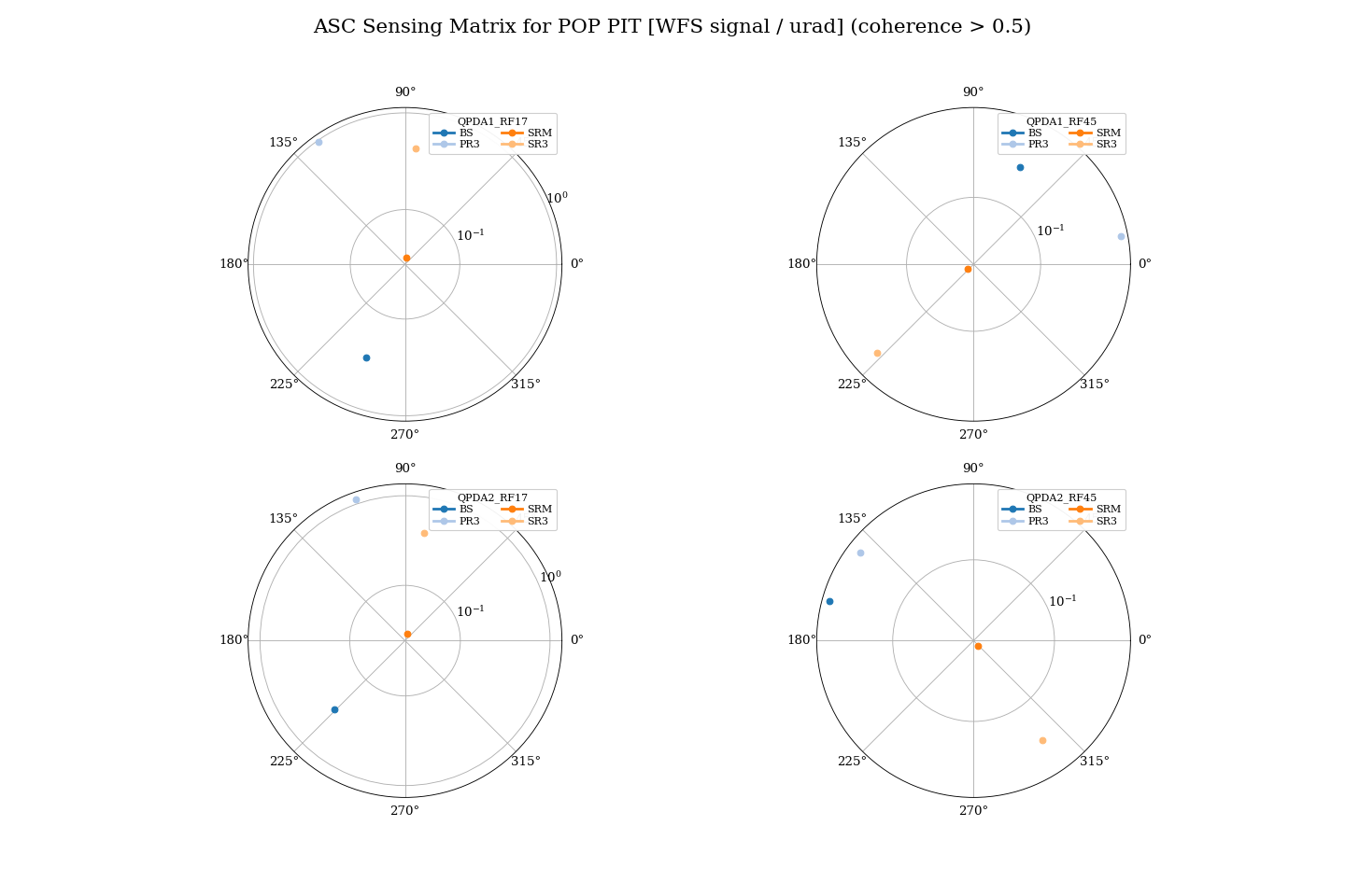
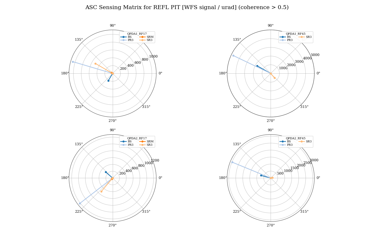
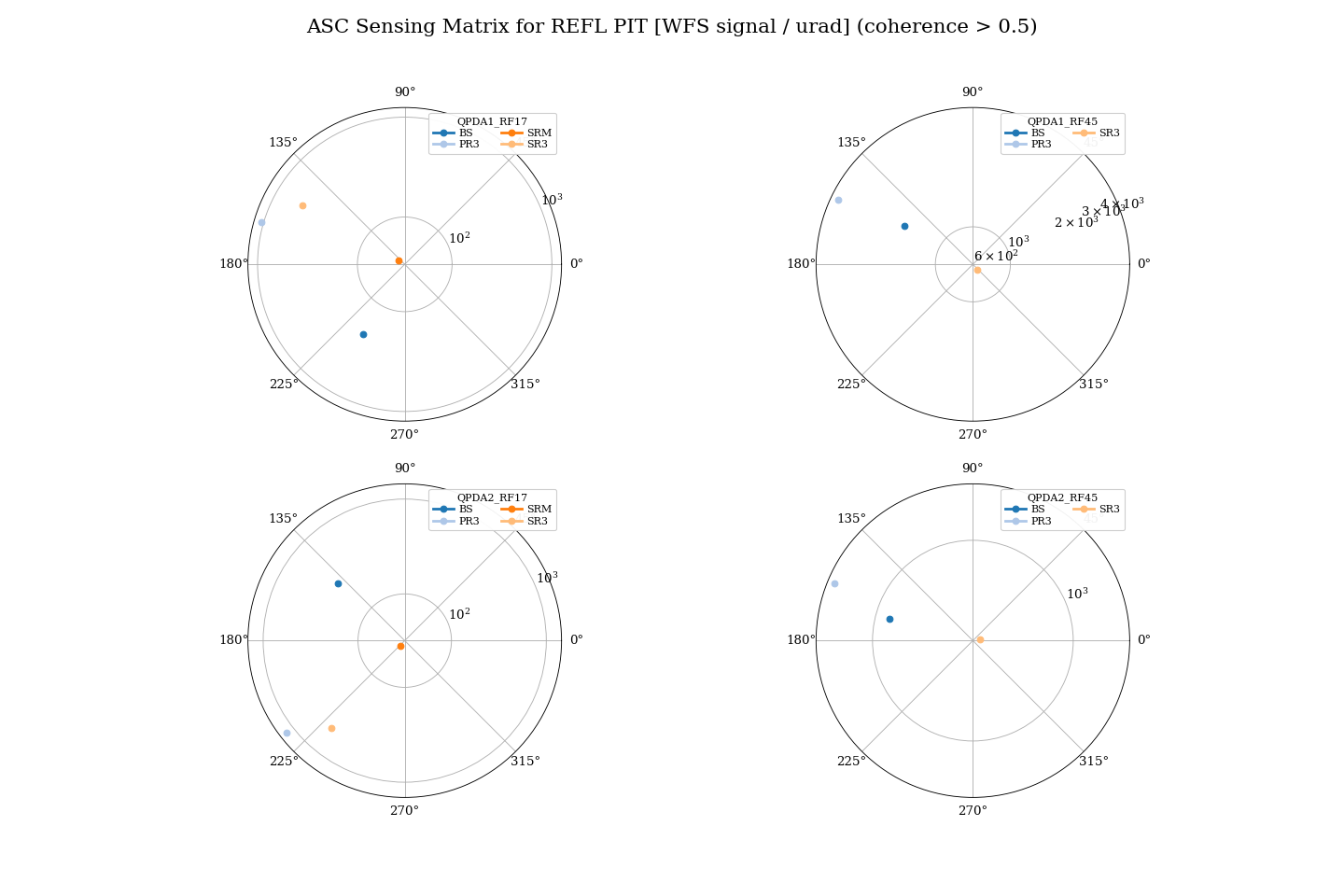
For each QPD, the responses of BS, SRM, SR3, and PR3 were plotted on a polar plot as a function of the demodulation phase.(FIG1-FIG8)
(Data: /users/Commissioning/data/ASC/2026/DRMI/0818/RFQPD_OPLEV_{BS, SRM, SR3, PR3}_P_260818.xml )
For REFL RF17 in the PIT direction, the BS response is nearly orthogonal to the other degrees of freedom. Therefore, it seems possible to separate the BS signal from the other signals by adjusting the demodulation phase. However, the responses from SR3 and PR3 are relatively large.
For AS RF28, the responses from SR3 and PR3 are also large. If the demodulation phase is set approximately 45 degrees from the BS response, we may obtain a signal that is more sensitive to SR3 and PR3 than to BS.
We also organized the script used for this measurement. In this measurement, all mirror degrees of freedom are excited at the same frequency using diaggui, and the WFS and OPLEV signals are measured. The script reads the saved diaggui files and plots the WFS responses in the complex plane to investigate the demodulation phase.
The scripts are stored in the directory below: /users/Commissioning/scripts/asc/WFS_sensingmatrix
The main settings are specified in "main.py". However, some paths in the Python scripts used to load the data may need to be changed. I plan to modify the scripts so that most of the settings can be controlled only from "main.py".
Next step
- Measure the sensing matrix in the YAW direction. -> However, when PIT and YAW use the same RFQPD, only one demodulation phase can be set for each QPD in the model. Therefore, if we set the demodulation phase based on the PIT direction, we may be able to skip the YAW measurement and start applying the control.
- Check the connection of the PZT mirror mount for REFL QPD3 PIT.