[On 28 Nov. 2017]
[Annalisa, Eric, Akutsu for Team WFS]
(Report by Annalisa, posted by tomo)
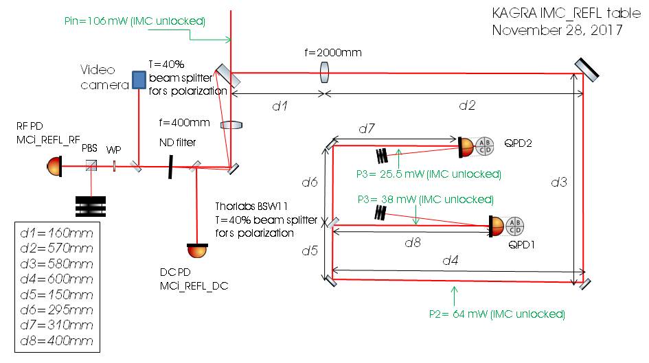
We worked on the MCi REFL bench. The main aim was to trace the REFL beam path up to the RF QPDs, to check whether there was any strange behavior. We made a schematics of the bench, taking note of all the optical components and lengths, which is reported in the attached figure.
The power was measured in four different points, which are reported in the attached bench schematics.
Basically we have (IMC unlocked):
- 106 mW at the bench input, at the periscope
- 64 mW along the QPD beams path
- 38 mW on QPD1
- 25.5 mW on QPD2
When the mode cleaner is locked, the power on the two QPDs drops to about 1/3rd of the previous power, which is 13.3 mW on QPD1 and 8.6 mW on QPD2 which means that the mode-matching is far to be perfectly tuned.
What we noticed during the power measurements was that the BS which were supposed to be 50:50 where actually splitting the beam with a different ratio (~60:40) . We took note of one of the models (BSW11 50:50) and we found out that for S-polarized light @1064nm the transmission is 40%, and that explains the different power that we measured.
After that, we took a measurement of the beam profile in front of each QPDs, and then an additional one 50 cm before QPD1 in order to trace the beam waist and check the Gouy phase between the two QPDs. Unfortunately, these measurements were not enough to properly characterize the beam, so we should repeat the measurement and take more points. Then, we first removed the beam dump in front of QPD1 then we realigned the beam on both QPDs, and we damped the reflections of both the QPDs.
Finally, there are two more things to report:
- the DC cable connectors of the two QPDs were pretty loose, and it was not possible to fix this problem by screwing them tighter.
- Secondly, along the locking PD beam path a neutral density filter is installed, which seems not to be the best option.