[Saito, Komori, Ushiba, Miyoki, Fujimoto]
Abstract
We borrowed a high-voltage amplifier from Miyoki-san and tested it for use in the PLL for the PRCL/SRCL length measurements.
The measured results are as follows:
- Gain: 20 dB
- Phase delay: ~1 deg at 10 kHz, and ~45 deg at 509 kHz
- Input-referred noise: ~1.4e-8 V/rtHz at 1 kHz
Tomorrow, we plan to implement this amplifier in the PLL control in order to extend the range of the PLL scan and increase the UGF.
Details
The current PLL scan range in the PRCL/SRCL length measurement is limited by the output range of the SR560, which is ±5 V. This corresponds to a scan range of about ±10 MHz.
Therefore, in order to extend the PLL scan range, we decided to introduce a high-voltage amplifier made by Miyoki-san, which is the same type as the one used for the EOM in the CARM control.
Instruments
We borrowed a high-voltage amplifier (PA-85), shown in Fig. 1, and its power supply, shown in Fig. 2.
The gain is fixed at 20 dB, and there is no offset. A banana-plug-to-Hirose-4-pin cable is used for the power supply connection.
Since the PZT input range of the Mephisto is ±65 V, we will set the supply voltage to about ±60 V when using this amplifier.
Transfer function
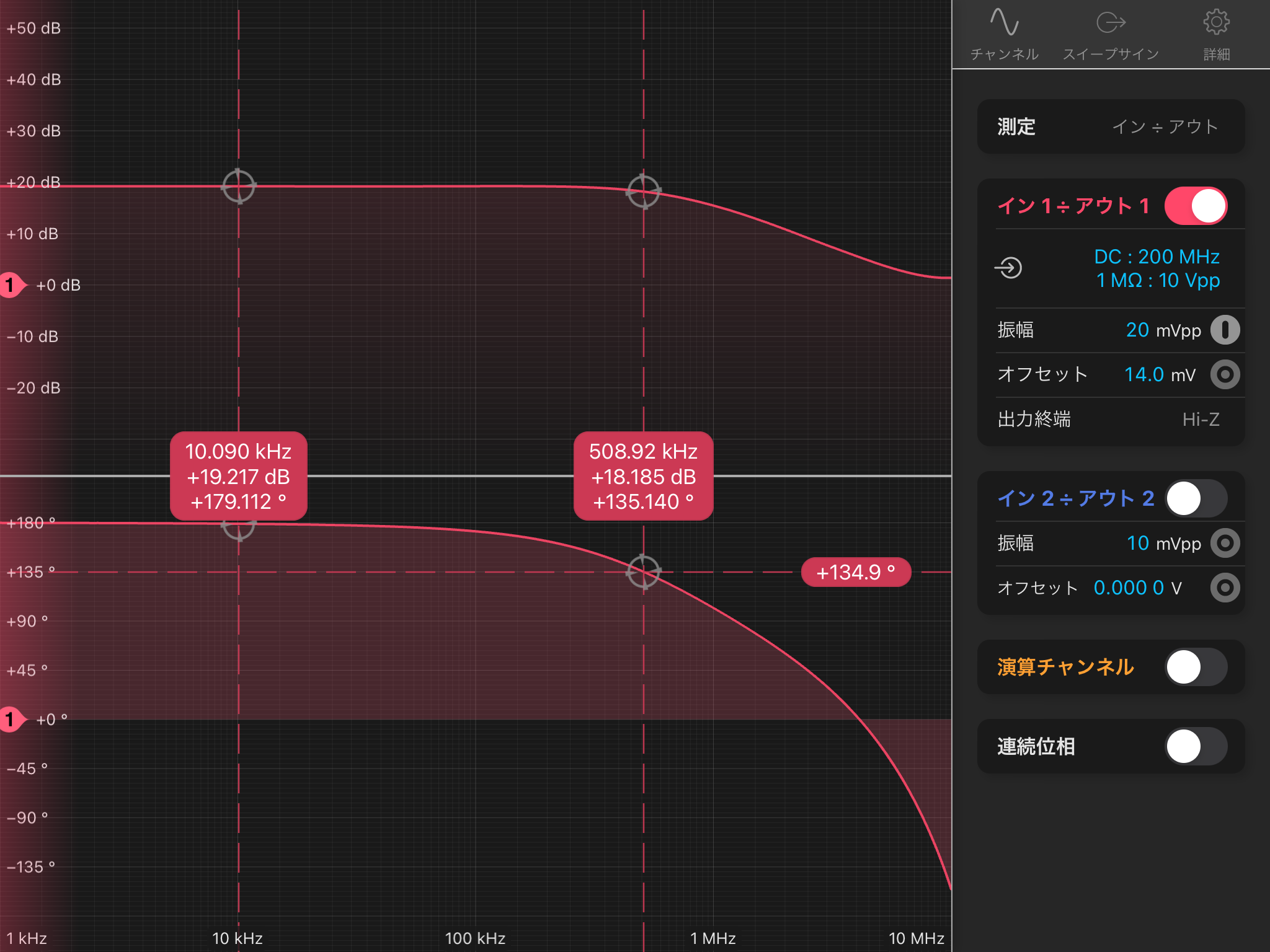
Fig. 3 shows the transfer function measured with Moku:Lab. The results are as follows:
- Gain: 20 dB
- Phase delay: ~1 deg at 10 kHz, and ~45 deg at 509 kHz
The phase delay is quite small for a high-voltage amplifier. Therefore, we expect that a UGF of 10 kHz can be achieved even with this amplifier.
Input-referred noise
In Figs. 4 and 5, red lines show the output noise measured with Moku:Lab and the black lines correnspond to the Moku: Lab ADC noise.
Taking into account the ADC noise of Moku:Lab, the input-referred noise of the high-voltage amplifier is estimated to be as follows:
- ~7e-9 V/rtHz at 10 kHz–100 kHz
- ~1.4e-8 V/rtHz at 1 kHz
In the actual control system, this amplifier will be connected after the SR560, whose gain is expected to be 300–3000. Therefore, the input-referred noise levels above are considered to be negligibly small.
Plan for tomorrow
Tomorrow, we will implement this amplifier in the PLL control and optimize the OLTF by increasing the UGF, adjusting the integrator, and making other necessary changes.
In addition, since this amplifier will extend the PLL range, we plan to perform the PRCL/SRCL length measurements with a larger scan amplitude.


