[Takano, Tanaka, Fujimoto]
Summary
While trying to lock the SRY on carrier resonance, we observed that the cavity occasionally locked to a dark state at transmission even though the sign of the feedback control had not been changed.
We found that this phenomenon is a carrier anti-resonant lock originating from the low finesse (~4) of the SRY and the FSR difference between the SRY and SRC.
Details
While aligning the SRM for DRMI locking using carrier-locked SRY (ITMX: MISALIGNED_BF, PRM: MISALIGNED, Guardian: vertex/SRY_1F_LOCKED), we observed that the SRY transmission ports (REFL, POP, and AS) sometimes locked to the bright state (carrier resonant, Fig. 1), but occasionally locked to a dark (anti-resonant) state instead (Fig. 2).
Therefore, we investigated the origin of this dark lock.
Fig. 3 shows time-series data obtained during a cavity scan by applying an offset of 30000 to K1:VIS-PRM_TM_TEST_L_OFFSET.
The blue trace is the error signal (POP17-I), while the orange, green, and red traces are AS DC, POP DC, and REFL DC, respectively.
From the transmission resonance peaks and the error signal, it can be seen that an error signal with the same sign as the carrier resonant lock exists even at the anti-resonant point.
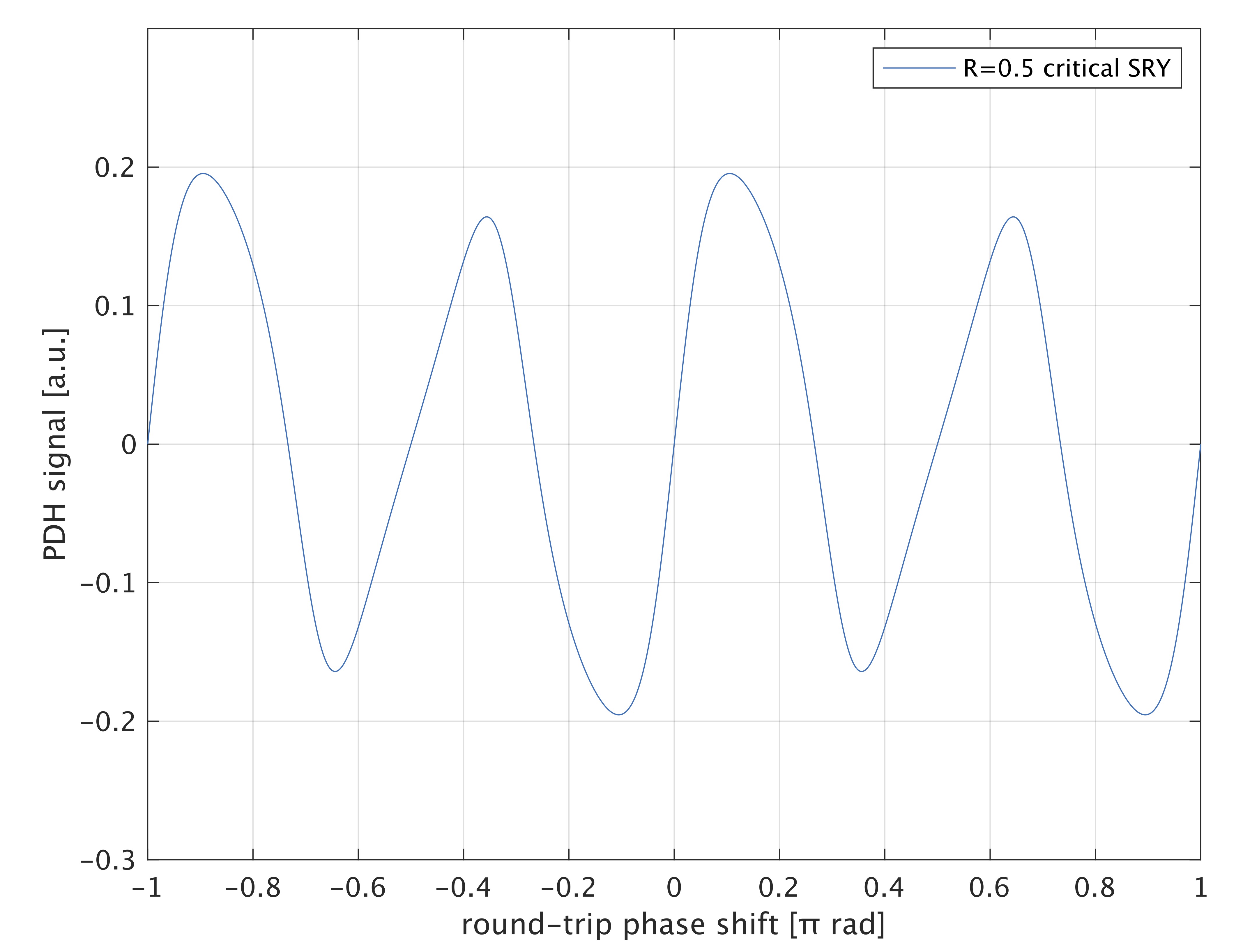
The same behavior is also reproduced in the analytical simulation (Fig. 4).
The origin of this anti-resonant error signal can be understood as follows.
Since the current cavity configuration is SRY, its FSR differs slightly from that of the SRC (FSR_{SRY}=2.20 MHz, FSR_{SRC}=2.25 MHz).
Therefore, when the carrier is resonant in the SRY, the f1 sidebands are shifted away from the perfect anti-resonant condition (= half-integer multiple of the FSR), corresponding to
f_1 = 7.68 * FSR_{SRY}.
In addition, the SRY is a low-finesse cavity (F~4) formed by (BS ⇒ ITMY ⇒ BS ⇒ SRM ⇒ BS).
As a result, when the carrier is anti-resonant, the f1 sidebands are located on the side lobe of the cavity resonance peak.
Therefore, fluctuations of the laser frequency or cavity length produce asymmetry in the amplitudes of the sidebands transmitted through the SRY and entering the POP RFPD, generating an AM sideband component.
This AM sideband component beats with the carrier transmitted through the anti-resonant SRY, producing an error signal even at the carrier anti-resonant point.
This is the origin of the SRY dark lock.
If we wants to avoid this dark lock in the SRY, the feedback loop can be enabled/disabled using a trigger based on the transmission power.
As an additional remark, if the sign of the feedback control is inverted, the cavity locks on the side lobe of the transmission peak (Fig. 5).
The reason why this control point is slightly shifted from the sideband resonance frequencies (carrier resonance frequency ± 0.32 MHz) is presumably that the carrier light acting as the local oscillator is located on the side lobe of its resonance, introducing an additional phase shift and effectively changing the optimal demodulation phase.


