[Tanaka, Hirose, Saito]
We confirmed that the Moku:Lab was operating properly. We also set up the system so that the local oscillator frequency could be continuously adjusted while monitoring the beat signal frequency. Although various types of filters were tested, the control system unfortunately did not function.
- Following the previous attempt (klog:36845), we continued working on the PLL. First, to verify that the Moku:Lab was functioning correctly, we connected its output to its input and confirmed that a constant voltage applied at the output was observed unchanged at the input. Next, we confirmed that the error signal was properly output when passed through a flat (0 dB) filter.
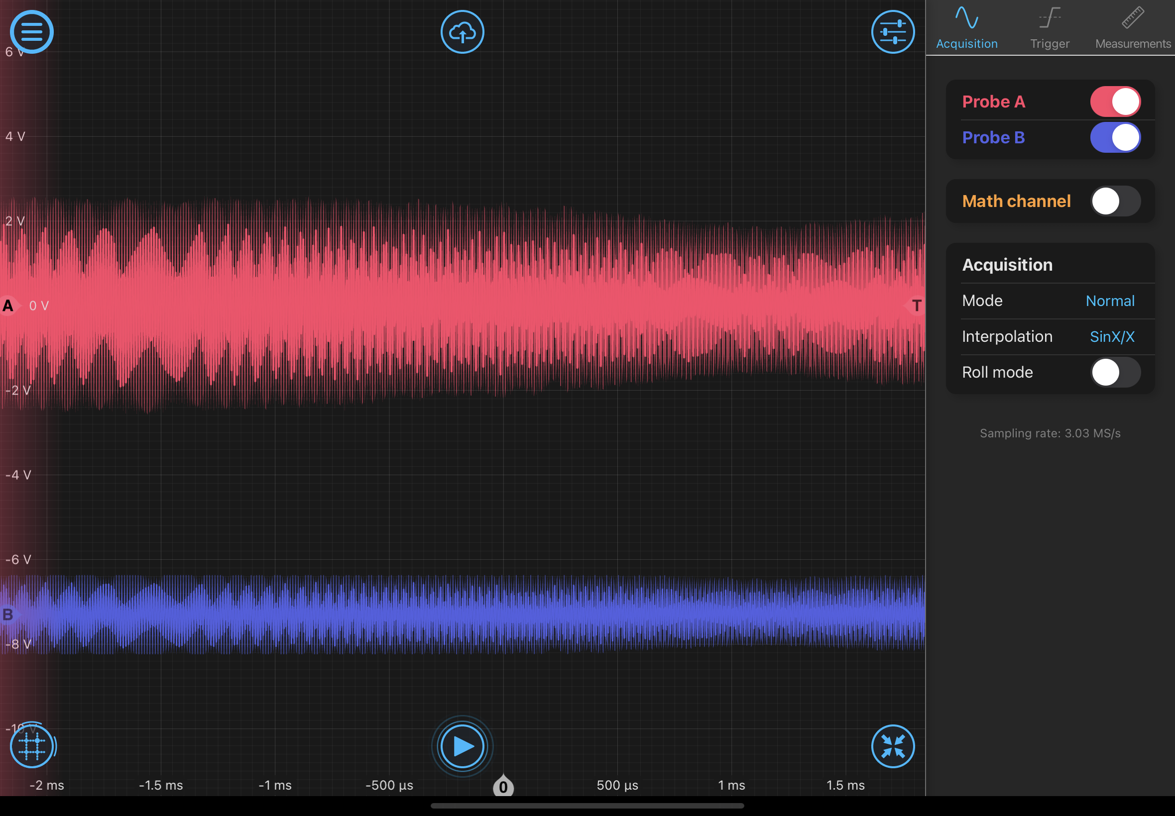
We then split the beat signal into two using a power splitter and used an additional Moku:Lab as a spectrum analyzer to continuously monitor the beat signal, allowing us to match the local oscillator frequency accordingly. Observing the mixed beat signal and local oscillator signal on the Moku:Lab oscilloscope, we saw that the amplitude of the error signal fluctuated and its frequency also varied (Photo 1). The red line represents the error signal, and the blue line represents the feedback signal. In this state, we applied various filters, including flat, high-pass, and low-pass filters, but no significant change in the error signal amplitude was observed. We also attempted to measure the open-loop transfer function; however, it did not appear that any meaningful measurement was obtained. Therefore, it is likely that feedback was not properly established. In addition, since the feedback signal amplitude was limited to a maximum of ±1 V, it may have been too small to achieve lock. It may be necessary to amplify the signal using an SR560 or a similar device before feeding it back to the laser PZT.
