Reports 1-1 of 1 Clear search Modify search
PEM (Center)
Carl Blair - 17:13 Thursday 19 February 2026 (36398) Print this report
jitter coupling measurements

[Alex, Carl]

We made a series of jitter to darm coupling measurement in pitch and yaw driving pzt1 and 2 on the psl table between 50 and 500Hz.  We found resonances of the piezo mirrors at 150Hz and a second one we will report later.
The measurements will be processed and reported tomorrow. 

Comments to this report:
Alexandra Adam - 11:24 Monday 23 February 2026 (36418) Print this report

[Alex, Carl]

We analysed the data from the injections around 100 Hz.  We found PZT1 has a resonance at 150Hz.  We found the worst case upper limit of coupling to be a factore of  below DARM in amplitude.  We found the coupling to DARM at the 150Hz resonance to be a factor 1.2 (amplitude) below DARM.

We drove PZT2 with a bandpass filter from 50-150 Hz of whitenoise. For PZT1 we found that the drive was exciting a resonance at 150 Hz so the filter was changed to 50-130 Hz. In this frequency band we found that the coupling into darm was too small to give a coupling function over most of the frequency bins and instead mostly gave an upper limit. We used a darm threshold of 2 and a witness sensor threshold of 2.5 as described here. The witness sensor used was IMC-REFL_QPDA2_DC* which had the highest coherence in the frequency band. 

The resonance at 150 Hz was visible as a small peak in the background of the IMC-REFL_QPDs and grew when we excited PZT1 with the strongest response being when pitch was excited. This implies a level of background excitation of the resonance. It was measured as a coupling function in the coupling of PZT1 pitch to the IMC-REF_QPD and appears close to DARM.

To estimate the overall effect on darm we added the upper limits from each PZT in both YAW and PITCH. The PZTs are not orthogonal so this provides a worst case scenario coupling. Overall this gave the upper limit of beam jitter coupling as a factor of 2.3 below darm (in psd units) from 50-130 Hz. 

Images attached to this comment
Alexandra Adam - 15:27 Tuesday 24 February 2026 (36427) Print this report

[Alex]

There was an error in the coupling function estimates, the correct plots are attached. There are now sufficient coupling factor points that a total upper limit can be found for the 150 Hz point which is now overprojected onto darm. (The crosses show upper limits and the dots show coupling factor)

Images attached to this comment
Carl Blair - 16:36 Tuesday 24 February 2026 (36426) Print this report

We used a combination of PZT1 and PZT2 on the PSL table to try to replicate the coupling function of the shaker 4 injection on the PSL table. We drove at 245Hz. The geometric factor for the coupling to be dominated by Mirror M17 would be about 0.25 while the observed ratio to replicate the coupling factor was about 0.025. This might mean coupling at 245Hz is dominated by a mirror closer to PZT1. It more likely means the coupling function (used here) is not accurate at 245Hz. This injection should be done closer to the 215Hz resonance frequency to confirm.

We used the PSL layout here. L8 and L9 are ignored for the moment. To achieve a beam rotation about a position X where PZT1 is at position A and PZT2 is at position B a gain of Ag = 0.4 and Bg = -0.4*(X-A)/(B-X) is applied to the drive to each PZT. If M17 is the suspect mirror the expected gain to match the coupling function with the shaker and the coupling function with the PZT would be -0.4*190/770 = -0.1.

A signal was injected at 245Hz with the drive split between PZT1 and PZT2 with this ratio (brown trace in the attached figure). This is compared to the shaker 4 injection (red) as witnessed by the IMC REFL QPDA1 witness of jitter noise. It is many orders of magnitude off. By reducing the PZT2 drive to 0.01 the coupling function could be made to match the shaker coupling function in magnitude and sign. This would equate to a beam rotation around a point 35mm from PZT1. M16 is the closest mirror at about 50mm from PZT1. 245Hz is too far from the observed resonance at 200Hz to produce a good coupling function by taking the simple ratio in diaggui. But, I think this is a proof of principle that the coupling function could be used to identify which mirror is moving in shaker tests.

The purpose of this test was mostly to prove the principle of driving 4 degrees of freedom of jitter (pitch, yaw, beam position and beam angle) with the pzts on the psl table. We are still trying to work out how to diagonalise beam position and beam angle.

Images attached to this comment
Alexandra Adam - 17:06 Tuesday 24 February 2026 (36419) Print this report

[Alex, Carl]

We analysed the beam jitter measurements from 250-500 Hz. We found that beam jitter coupling was very close to DARM between 400-500 Hz however we believe this is an over projection and that better measuremennts with a higher SNR are needed. When we compared this coupling to DARM at 10W it seems that the coupling is different at higher power since the beam jitter does not limit sensitivity in this region.

We conducted measurements of the beam jitter in yaw using IMC PZT1 and PZT2 as drive and using IMC-REFL_QPDA*_DC_YAW_OUT_DQ as the witness sensors. This was done using a white noise injection with a bandpass filter from 250  to 500 Hz. Notched filters were used to reduce resonances of the PZT mounts. Both PZT1 and PZT2 had a resonance at 447 Hz and PZT2 had an additional resonance at 469 Hz.

The coupling for PZT1 (fig 1, 2 and 3) seemed to match DARM from 440-500 Hz including explaining a peak in DARM at around 490 Hz (fig 1 middle plot). However when we compare to DARM when the detector was operating at 10W and use the sensor noise from that time, the beam jitter overprojects darm (fig 1 bottom plot). This implies that the coupling function has changed since the detector operated at 10W, whether this is related to the change in power is unknown.

The coupling for PZT2 (fig 3, 4) is close to DARM but only touches darm at a few points.

Pitch has not been measured yet, we will measure pitch as well as remeasure yaw now that the sensor noise of the QPDs has been improved.


Images attached to this comment
Alexandra Adam - 11:54 Monday 16 March 2026 (36583) Print this report

[Alex]

Investigating if the Beam Jitter Coupling has Changed

Summary: The beam jitter coupling has become worse since July 2025, especially around 350 Hz. This seems to be a real change in the coupling and not just an increase in the amount of beam jitter. We're not sure why it has increased but it may have something to do with warming up the detector or reducing the power.

Background

A few weeks ago we (Carl and Alex) made measurements of the beam jitter coupling from 250-500 Hz we noticed that the beam jitter projections were very close to darm and even over-projected at some points. We were confident that the coupling function was reasonable accurate since we had a high SNR is our noise injections in the witness sensors and DARM. This was concerning we know that DARM was lower when the detetector was operating at 10W in July but the detector noise was also lower in the regions that we were projecting beam jitter.

We manually fitted the shot noise component to DARM in order to estimate the techincal noise in this region.

This also implied that the technical noise was much higher now than in July. This left us two posibilities: the beam jitter has increased or the detetector is now more sensitive to beam jitter.

Witness Sensors

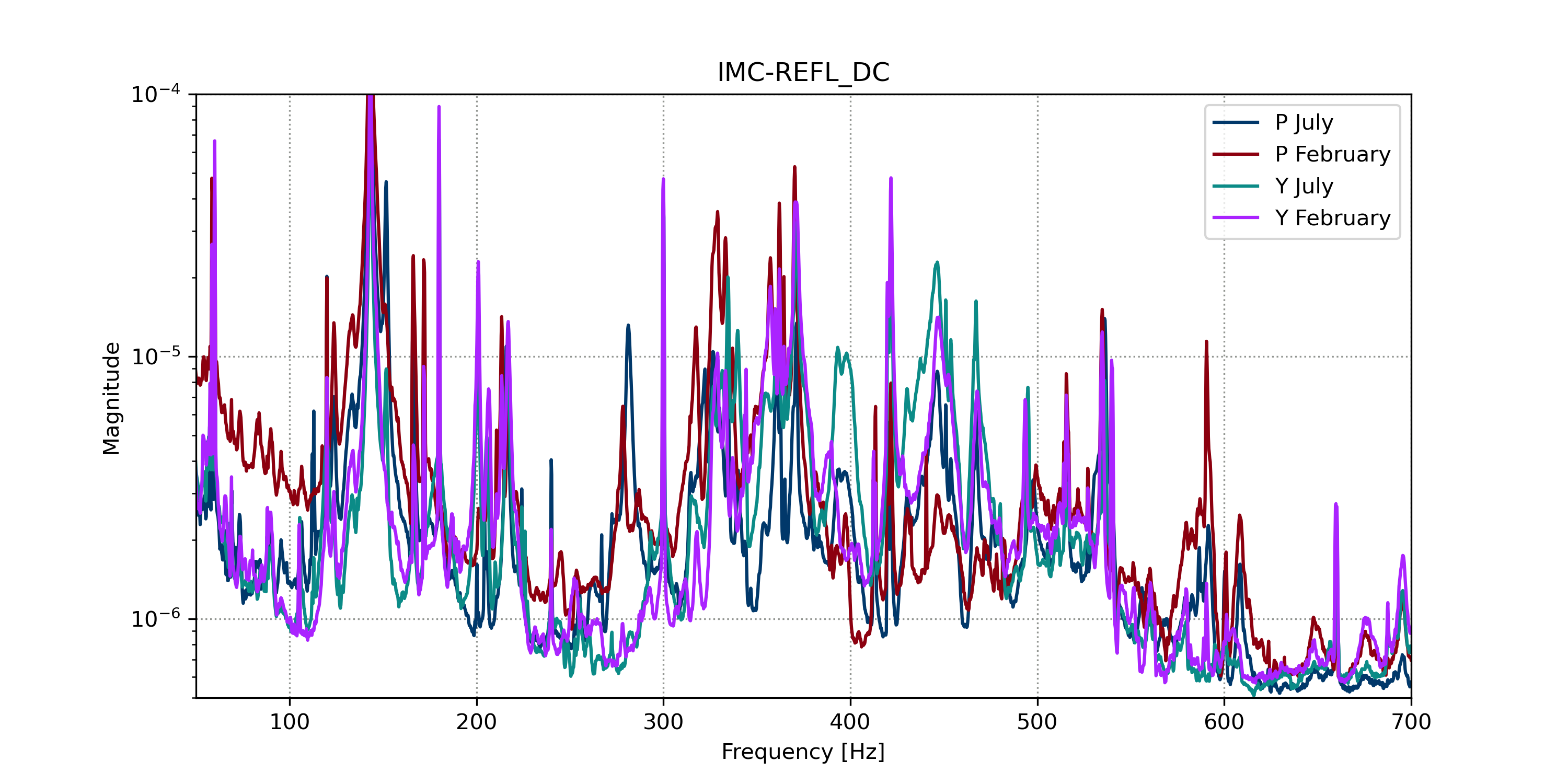
I chose to look at the IMC-REFL_QPDA1_DC since we had engaged the whitening filters on the RF channels for the time period I was looking at, as far as I am aware has have been no changes to DC sensors since O4. The noise spectra of the sensors did not appear to show any major differences between July 2025 and Februrary 2026. The spectra in february do show an increase level of noise in in the peaks around 350Hz but the increase does not correspond with the same increase in DARM.

I then looked at the coherence of these sensors with DARM which showed that the coherence had increased significantly in this region.

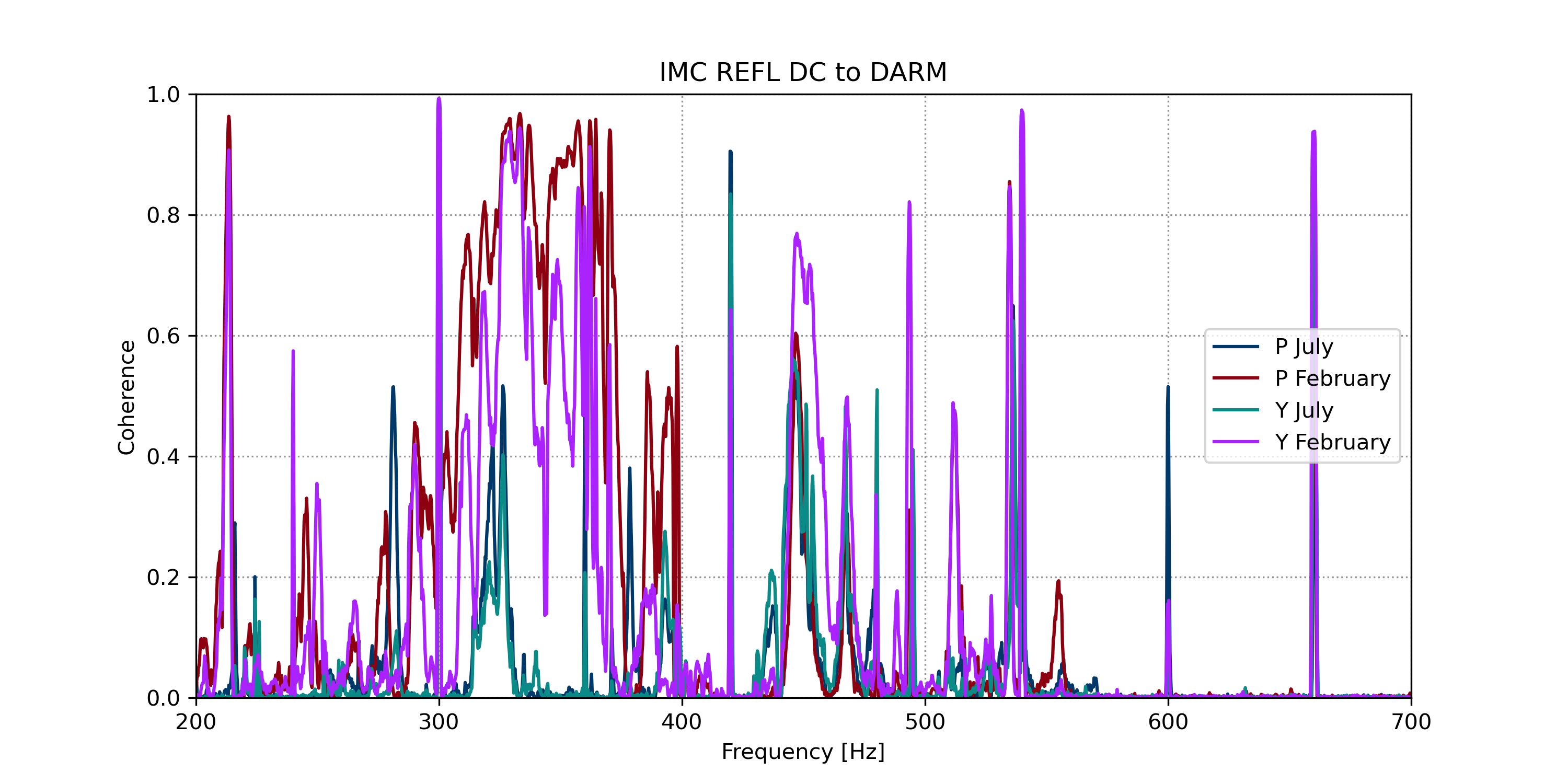
This implies that the coupling function has changed so that the detector has become more sensitive to beam jitter. I then decided to try and estimate the coupling function in July and Compare it to now.

Coupling Function Estimates

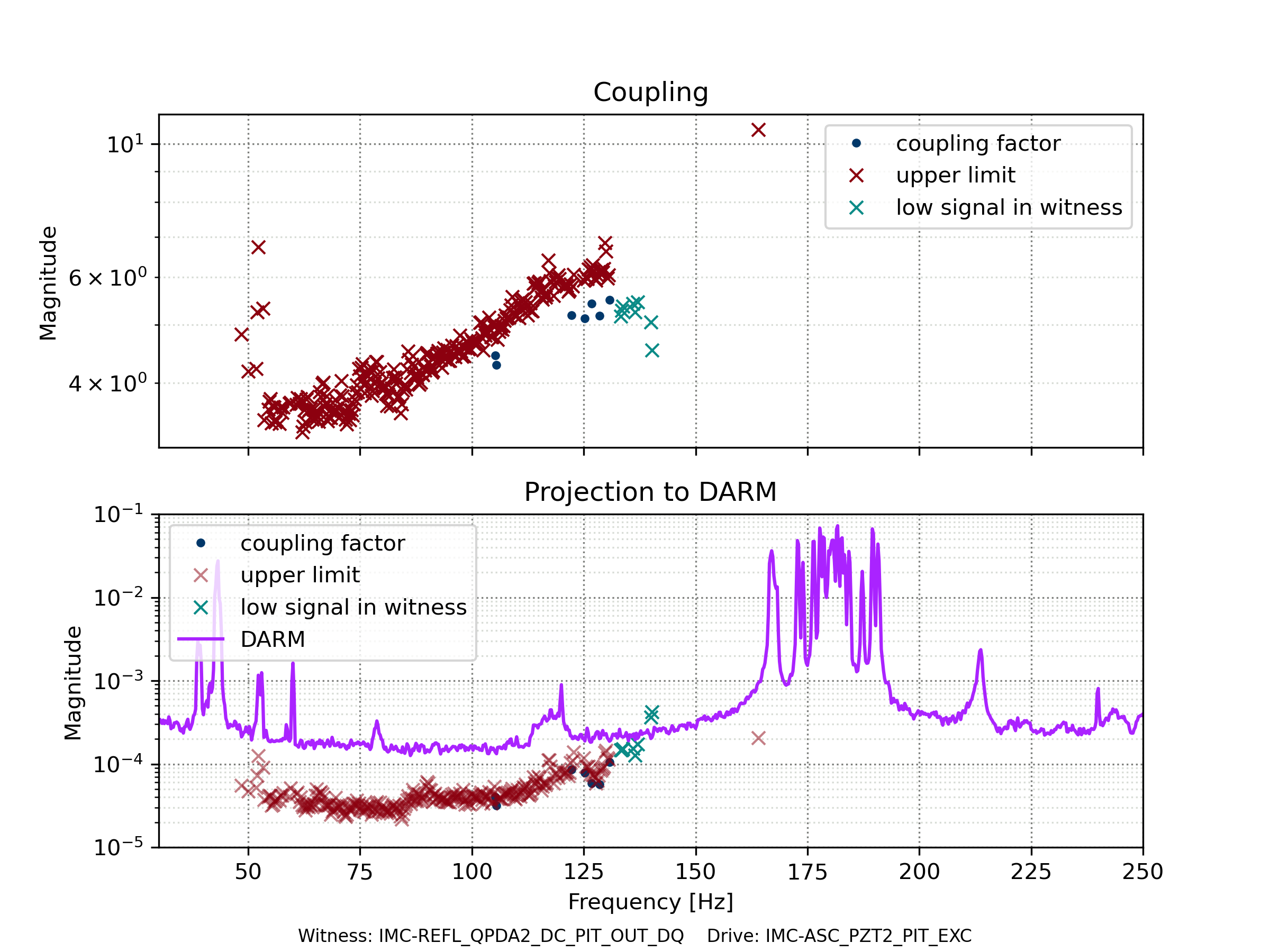
Ideally to measure the coupling function we would perform a noise injection, however this is not possible since we are looking at past data. Instead I used the method given in Davis et al which describes on the ways that noise subtraction was done at LIGO Hanford. This uses the cross spectra density to estimate the transfer function from multiple witness sensors to DARM.

The cross spectral density is defined as:

c1,2(f)=Y1(f)Y2(f)c1,2(f)=Y_1(f)Y^{\ast}_2(f)

where Y1 and Y2 are the fourier transforms of the time series. The coupling function for each witness sensor is then defined as:

(CF0,1CF0,2...CF0,N)=(c1,1c2,1...cN,1c2,1c2,2...cN,2............c1,Nc2,N...cN,N)-1(c0,1c0,2...c0,N)\begin{pmatrix} CF_{0,1} \\ CF_{0,2} \\ ... \\ CF_{0,N} \end{pmatrix} = \begin{pmatrix} c_{1,1} & c_{2,1} & ... & c_{N,1} \\ c_{2,1} & c_{2,2} & ... & c_{N,2} \\ ... & ... &...&... \\ c_{1,N} & c_{2, N} &...&c_{N,N} \end{pmatrix}^{-1} \begin{pmatrix} c_{0,1} \\ c_{0,2} \\ ... \\ c_{0,N} \end{pmatrix}

where CF is the coupling function and 0 is the target channel for noise estimation/subtraction and indices > 0 represent different witness sensors. In the case of N=1 this reduces to:

CF0,1=c0,1c1,1=Y0Y1Y1Y1=Y0Y1CF_{0,1} = \frac{c_{0,1}}{c_{1,1}} = \frac{Y_0 Y^{\ast}_1}{Y_1 Y^{\ast}_1}=\frac{Y_0}{Y_1}

which is the conventional definition of a transfer function. In our case we use a 2 channel estimation which witness sensor 1 being pitch and witness sensor 2 being yaw of the IMC-REFL QPDA1 DC. 

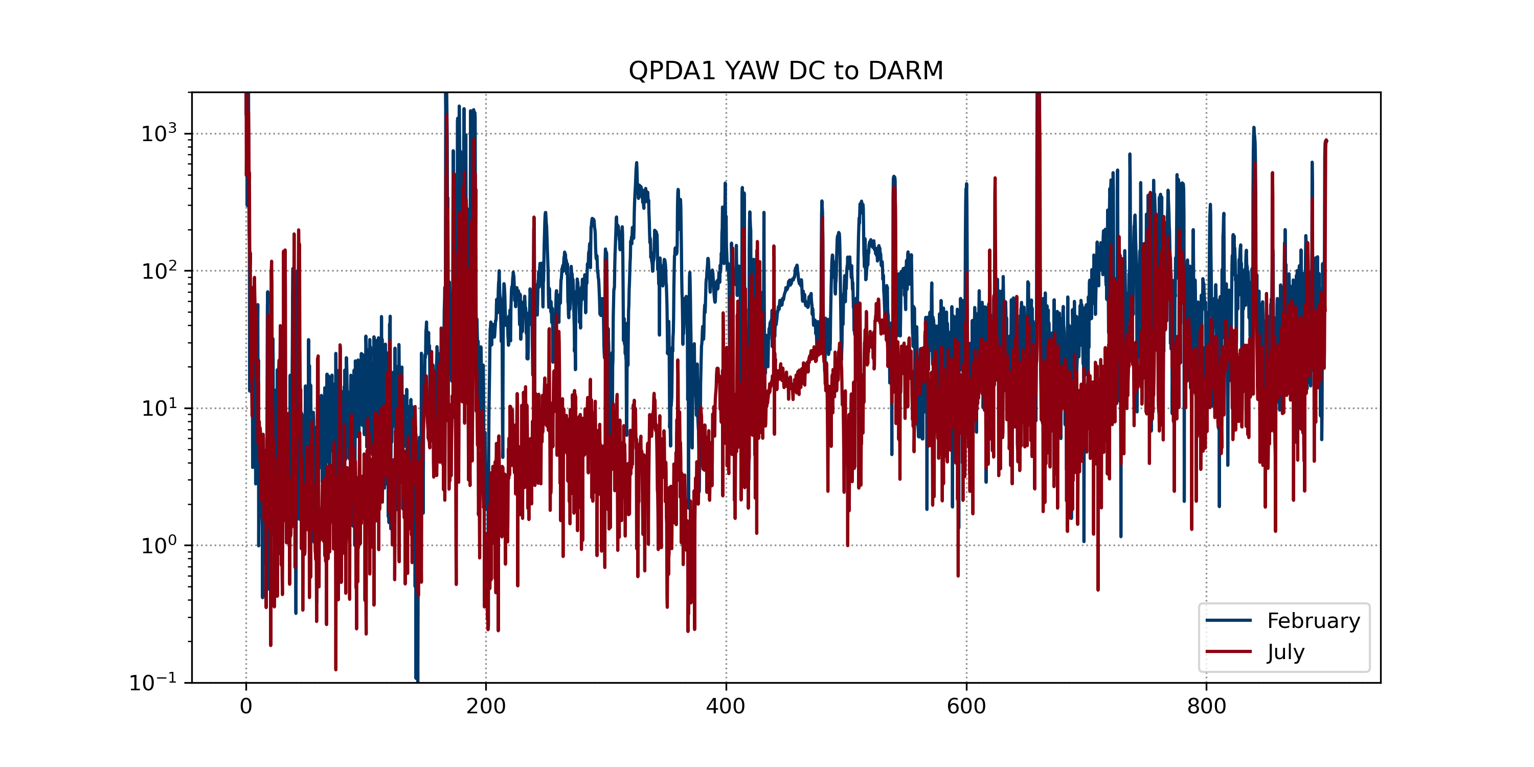
I took 1000 averages from 02/07/25 01:25:00 UTC for the July measurement and 1000 averages from 24/02/26 14:53:00 UTC for the February measurement. This gave the following coupling function estimates:

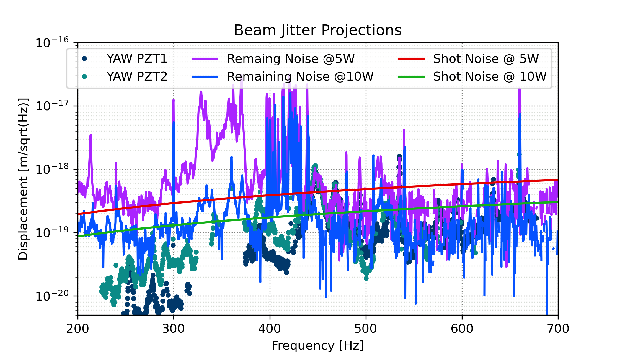
and the corresponding jitter noise projections:


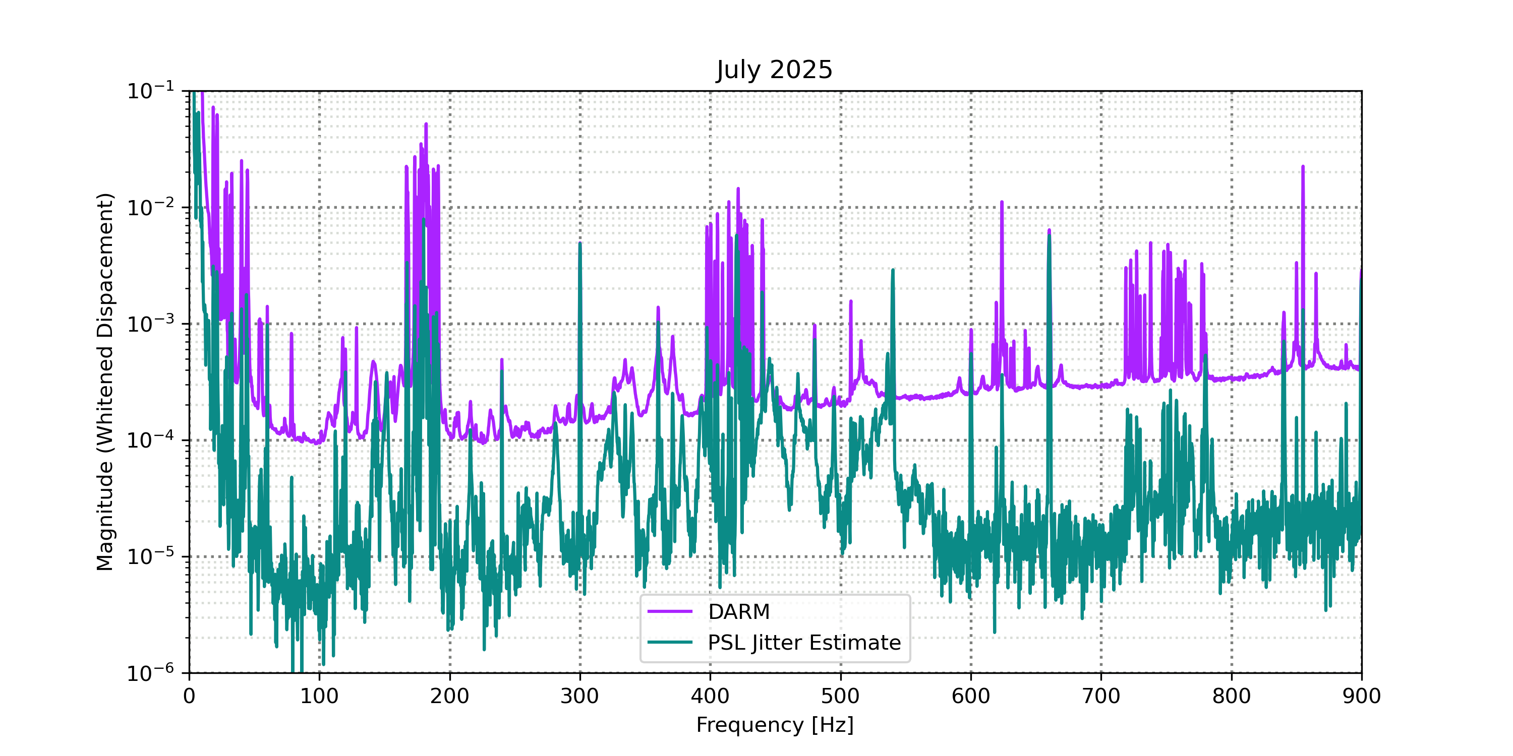
While there is obviously some overprojection these seem to match DARM reasonably well and show that the beam jitter noise has changed.

Causes and Solutions?

We don't know what has caused this but we know that the arm finesse has changed since the detector has warmed up so maybe the balance of the arms has also changed? As for a solution, not sure if what the solution is if we don't know the origin of the change, it's possible that going back to cryogenic temperatures and increasing the power again might reverse the change. It highlights the need for any noise subtration to be able to cope with changes in the coupling function over time.

Images attached to this comment
Search Help
×

Warning

×