Abstract:
Optimization of the CARM and IMC CMS boards has the potential to completely eliminate residual frequency noise below 5 kHz.
The key question to be addressed is whether the unity gain frequency (UGF) of the frequency stabilization loop can be increased to approximately 180 kHz.
Details:
In previous work (JGW-G2517117), future prospects for further suppressing residual frequency noise at high frequencies were proposed; however, these ideas have not yet been examined in the context of the actual CMS board implementation.
Here, I propose a new design for the CARM and IMC CMS boards and compare it with the current configuration.
| Current | My proposal | |
| CARM CMS Common and fast path | In1 gain: 0 dB | In1 gain: 0 dB |
| pole: 10 Hz, zero: 1 kHz | pole: 1 kHz, zero: 10 kHz | |
| pole: 10 Hz, zero: 1 kHz | pole: 1 kHz, zero: 10 kHz | |
| pole: 300 Hz, zero: 4.5 kHz | - | |
| Fast gain: -20 dB | Fast gain: 2 dB | |
| IMC CMS Common path | In1 gain: 25 dB, In2 gain: 7 dB | In1 gain: 25 dB, In2 gain: 2 dB |
| pole: 40 Hz, zero: 4 kHz | pole: 1 kHz, zero: 10 kHz | |
| pole: 1 kHz, zero: 20 kHz | - | |
| pole: 1 kHz, zero: 20 kHz | - | |
| pole: 300 Hz, zero: 4.5 kHz | - | |
| IMC CMS Fast path | Fast gain: 18 dB | Fast gain: 23 dB |
| Band pass: 2 kHz to 50 kHz, Gain: 1 | Band pass peak: 1 kHz, Gain: 300 | |
| - | pole: 10 kHz, zero: 100 kHz | |
| IMC CMS Slow path | pole: 4 Hz, zero: 400 Hz | [Pole: 1 kHz, Gain: 10] x2 |
| Pole: 30 kHz, Gain: 0.1 | Pole: 100 kHz, Gain: 1 |
Figures 1, 2, and 3 show the open-loop transfer functions of the IMC without the IFO, the IMC with the IFO, and the CARM loop, respectively.
The measured data are plotted as blue dots for reference, and the precise laser PZT actuator efficiency reported in klog:36088 is taken into account.
In the proposed design, the crossover frequency between the PZT and EOM loops is 23 kHz (phase margin of 30°), the UGF of the overall loop is 180 kHz (phase margin of 40°), and the CARM UGF is 27 kHz (phase margin of 55°).
The most important point is achieving a higher UGF of the overall loop by reducing the total time delay from the current ~1 us to ~0.4 us.
One potential approach to reduce the time delay is to remove the high-voltage amplifiers for the EOM by increasing the crossover frequency between the PZT and EOM loops and reducing the RMS of the feedback signal applied to the EOM.
If the intrinsic frequency noise around 10 kHz is approximately 1 Hz/√Hz, as suggested by the laser specification, the RMS voltage applied to the EOM should be on the order of 1 V, and the amplifier may not be necessary.
Further investigation is required to confirm whether the crossover frequency and the UGF can be increased as assumed.
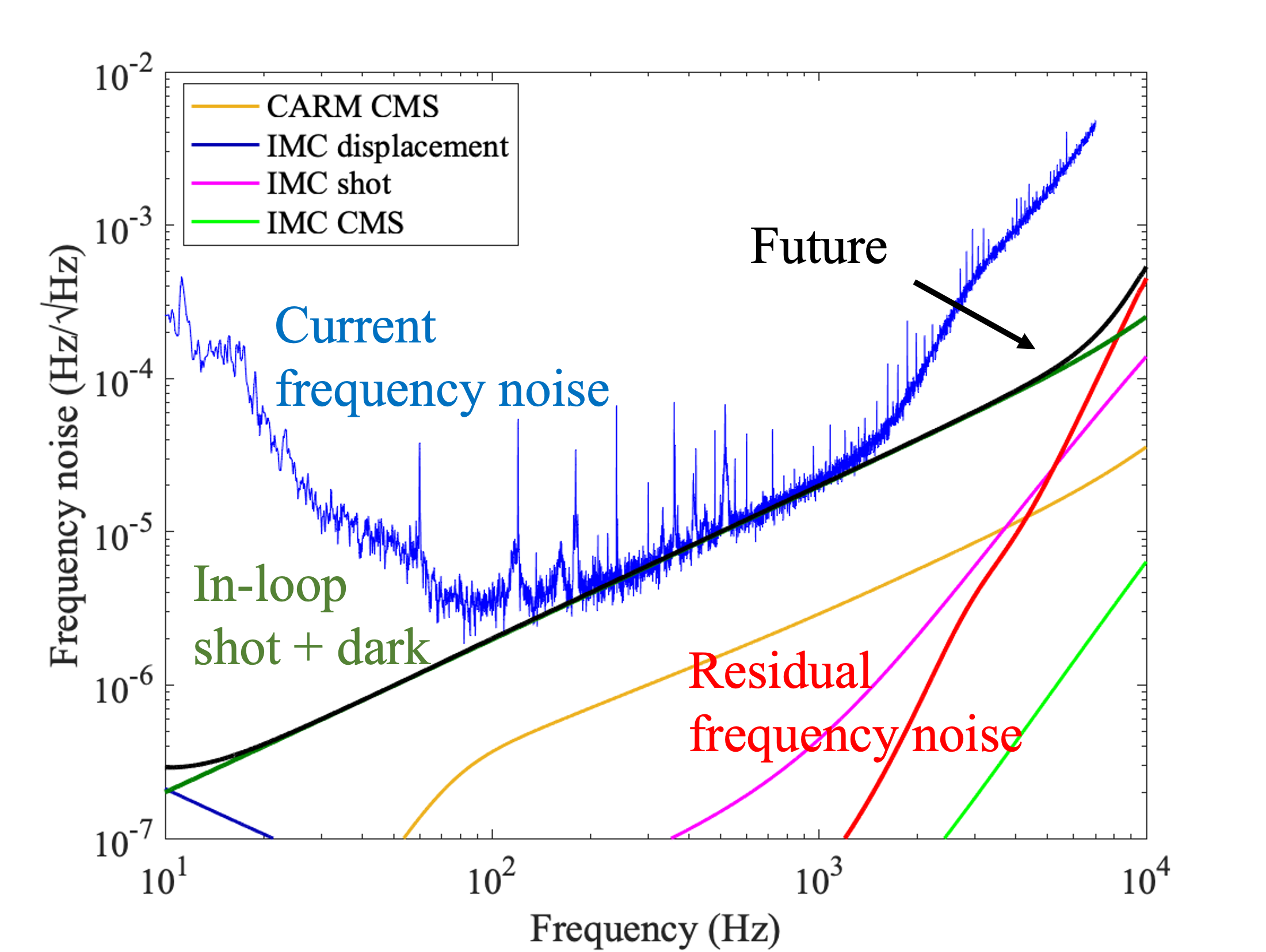
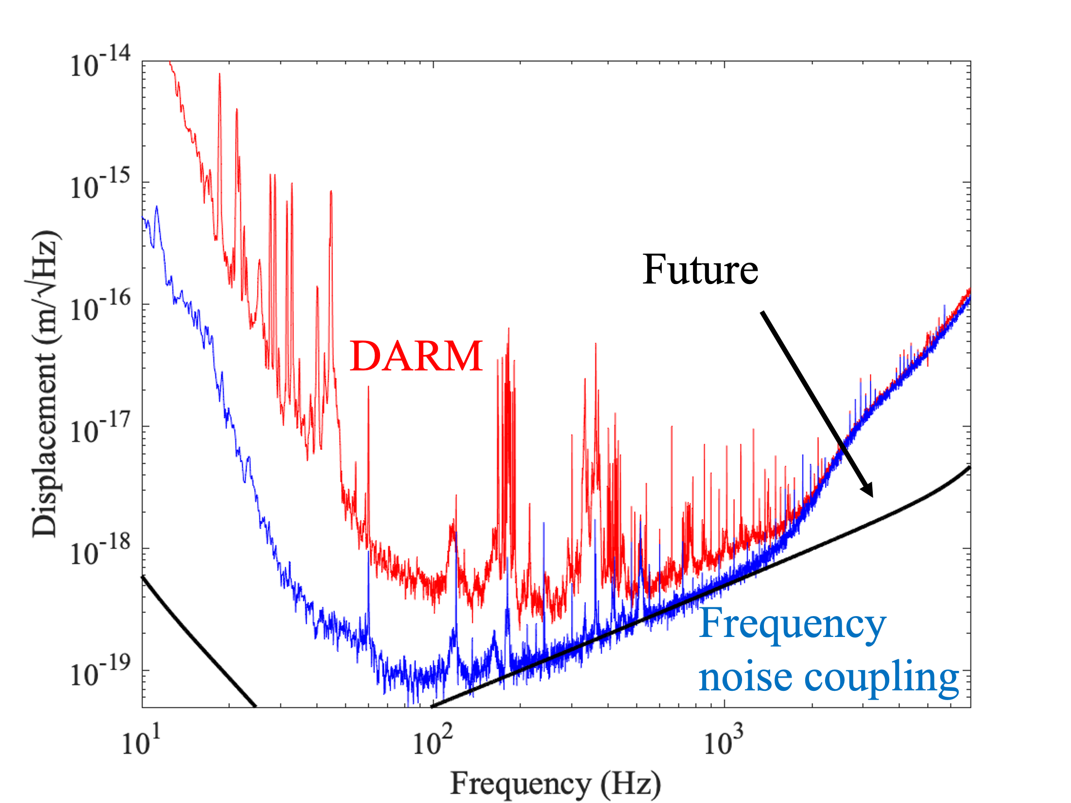
If the newly designed loop is successfully implemented, the resulting frequency noise spectrum is shown in Fig. 4, and the corresponding frequency noise contribution to DARM is shown in Fig. 5.
In this case, residual frequency noise below 5 kHz would be eliminated.
I will initiate discussions with site commissioners and AEL members regarding this proposed update.


