We tried to keep IFO at PRFPMI_RF_LOCKED state but GRY cannot be locked now somehow.
So, we gave up locking IFO.
In this morning, we noticed GRX also cannot be locked now.
Around 20:47 JST yesterday, GRX signals became strange (fig1).
At that time, GRY already could not be locked, so te broken time seems different for GRX and GRY.

If this issue is repeated without any problem on the electrical connections, RF reflections, etc., you may want to suspect a thermal problem. If so, please consider to put LOs outside of the rack. The ALS rack was one of the most warm field racks and temperature often went over 30degC a few years ago. By the way, major thermal sources were LO equipments themselves.
As a glitch hunting work around CMS, Ondotori devices were removed from each field rack (see klog#23222). So we cannot see a recent situation in the field racks and standalone temperature monitor is necessary to see the current situation. I'm not sure recent temperature in the corner station but if it increases since a few years ago, the field rack may also become more tough environment than the past one such as the 2nd floor of corner station (klog#34320).
GRX/GRY lock issue investigation
Date: 2025/10/29
Members: Takafumi Ushiba, Shinji Miyoki, Dan Chen
Summary
We found that the GRX signal became strange around 20:00 last night, and we investigated both GRX and GRY. As a result, we discovered that the power line inside the VCO chassis for GRX was loosely fixed and easily detached. The circuit has been brought back to Mozumi and will be inspected, repaired, and reinstalled tomorrow. For GRY, we found that the suitable phase difference between modulation and demodulation had shifted by about 135(? need to be confirmed as a exact value) degrees. After adjusting the phase of the function generator (FG), Yarm could reach the ALS_LOCKED state.
Details
-
Checked GRY function generator (FG)
The output settings were confirmed as ch1: 0 dBm and ch2: 10 dBm, consistent with the previous report. -
Power-cycled the FG
Tried to lock after restarting the FG, but still could not lock. -
Tried swapping FGs
Used the FG for GRX to drive GRY, but it did not lock and the signals were unchanged. -
Checked FG output signals
The FG output was normal. After restoring the original configuration (GRX with GRX FG, GRY with GRY FG), we noticed that GRX also could not be locked. The GRX signal had already looked strange since around 20:00 last night (see fig_001.jpg). -
Investigated the Dual I&Q Demodulator
Since both GRX and GRY could not be locked, we checked the common circuit, the Dual I&Q Demodulator (S1809168). Power-cycling it made no difference. Replaced it with another unit (S1809171), but there was still no improvement. (We continued using S1809171 after this.) -
Power-cycled the RFPD interface
No change; still could not lock. -
Checked signals around the I&Q Demodulator using MokuLab
- The RFPD signals for both X and Y were visible at appropriate frequencies, though the GRY signal was relatively smaller.
- Disconnected the EOM to check possible coupling effects.
- The LO signals from FG to the demodulator were large for both X and Y, though the X channel appeared slightly noisy.
- Signals just after the RFPD looked normal.
- When rechecking the I-Mon port, GRX showed a clear PDH signal, while GRY showed only a small one (see fig_002.jpg).
-
Checked the actuator side of GRX
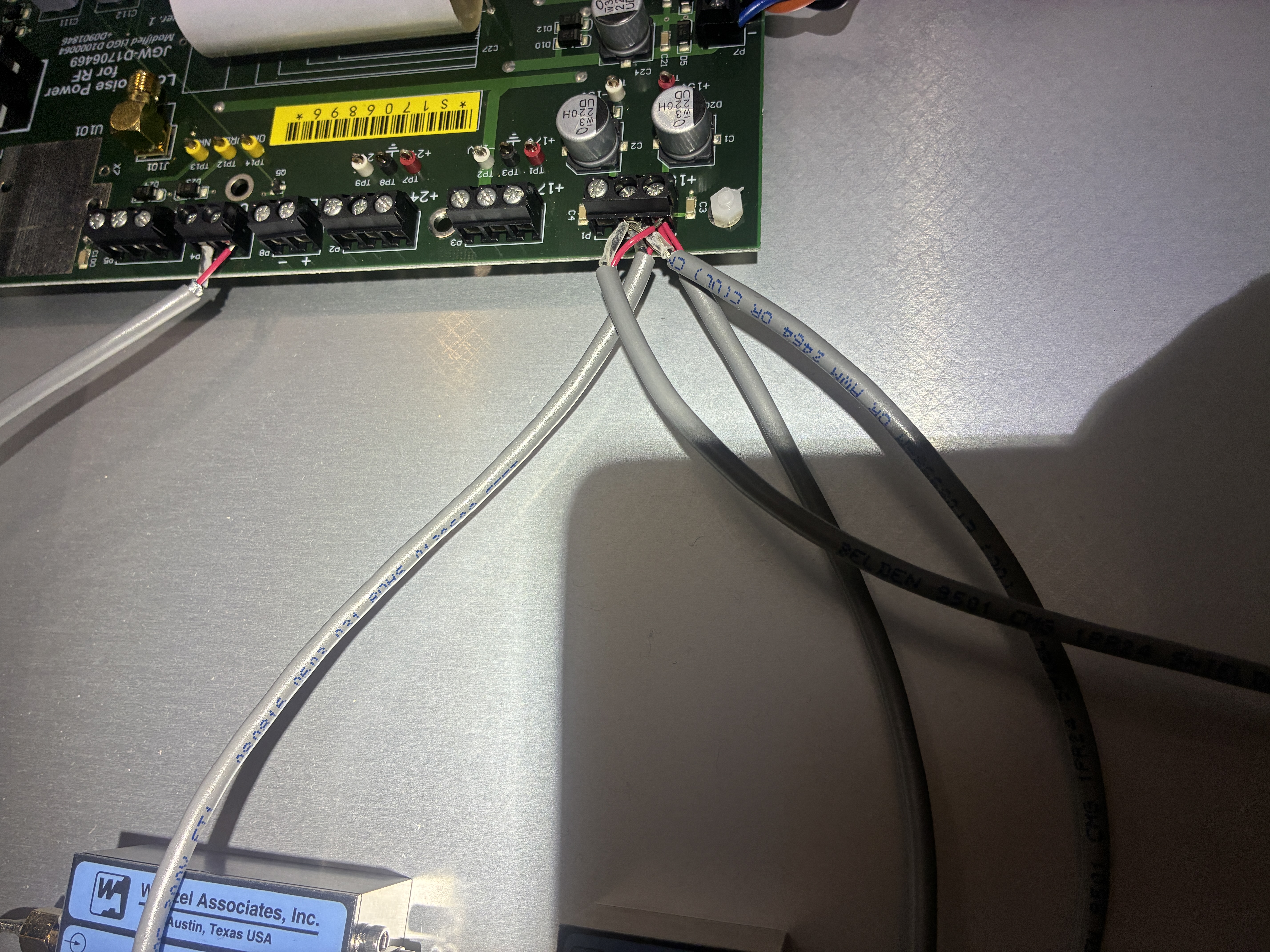
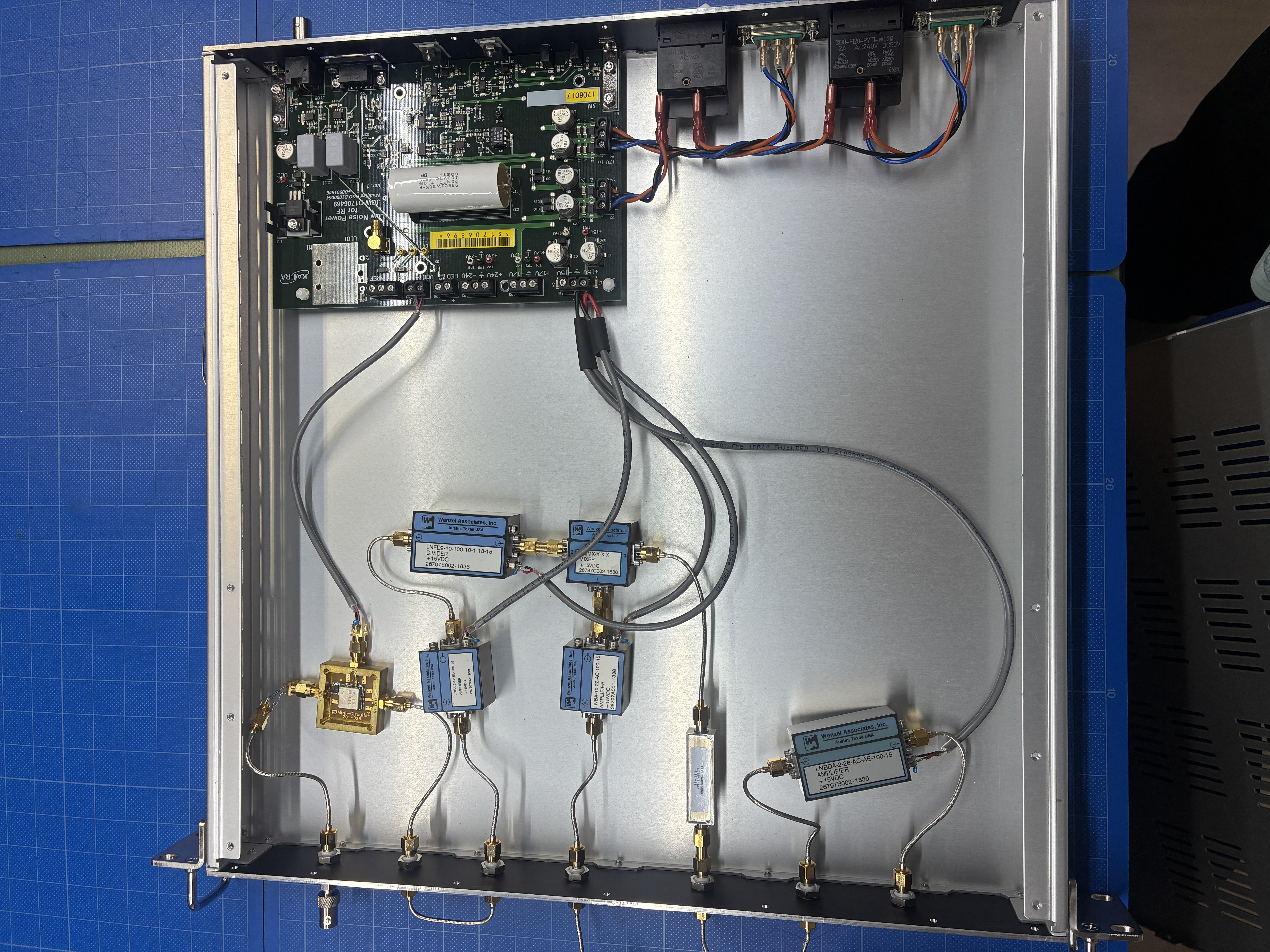
Since the PDH signal of GRX was clear, we suspected a problem on the actuator side for GRX. Using the GRY VCO circuit (S1809061) for GRX allowed us to lock. We then opened the original GRX VCO circuit (S1809060) and found that the power amp supply line inside the chassis was very loose and could be easily detached, and some solder joints were also poor (see fig_003.jpg). We concluded that this was the cause of the GRX issue. The circuit was brought back to Mozumi for repair. -
Checked the sensing side of GRY
Since the GRY signal was small, we investigated further. Using the IQ demodulator (S1809171) previously used for GRX, GRY could be locked by inverting the sign in software. Observing I-Mon and Q-Mon with an oscilloscope revealed that the suitable demodulation phase was shifted. After adjusting the FG demodulation phase to maximize the I-Mon signal, Yarm could be locked successfully. When switching back to the original IQ demodulator (S1809168), the lock was still successful. Therefore, it seems that the phase somehow shifted around 17:00 yesterday, which made the lock fail.
Conclusion
- GRY: Successfully locked after adjusting the demodulation phase of the FG.
- GRX: Found that the VCO circuit (S1809060) had a loose power supply line inside the chassis (fig_003.jpg). The circuit was taken back to Mozumi for repair and will be reinstalled tomorrow.


[miyoki, ushiba]
>8. Checked the actuator side of GRX
Photo.1 showed the power lines for four Wenzel parts in the VCO box for X. As you can see, 4 cables are tried to be clamped in one terminal segment for +15V and GND, individually. Actually, one of red cables seemed to be detached from the terminal when I opened the cover as Photo.2 .
Photo.3 shows detached each power line.
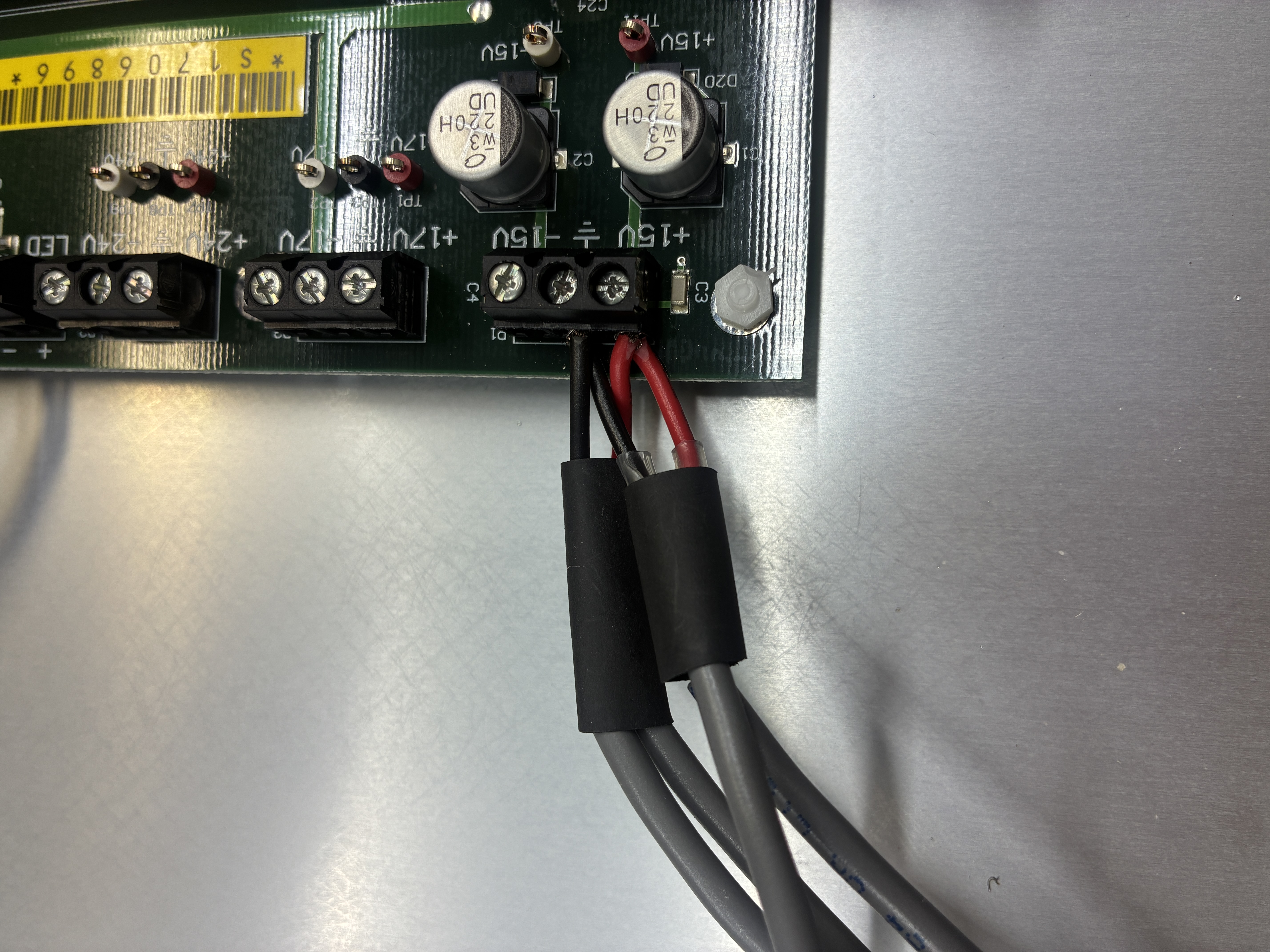
Fig.4 shows the improved connection of these powe lines. The power lines and GNDs for two Wenzael parts are solded with each other with a single red(for +15) and black(for GND) lines, individually, then new two red and black lines are fixed in the terminals.
Fig.5 shows the top view inside of the VCO box. The left bottom Wenzel part's poweline seemed to be loosened maybe during some activities yesterday, then completely detached in the last night.
After improvement, we checked VCO performance. Anyway, we can confirmed that the output frequency (~ 79.5MHz) can be changed according to the applied control DC voltage. So, the trouble reason seemed just to be the detached power line cable.


Recovery of GRX lock and RF_LOCKED was achieved
Date: 2025/10/30
Members: Takaaki Yokozawa, Dan Chen
Summary
The repaired VCO circuit for GRX was reinstalled in the original configuration. After reinstallation, we tried locking the Xarm and successfully reached the ALS_LOCKED state. Then, we performed the initial alignment, and the interferometer recovered to the RF_LOCKED state.
Details
We installed the repaired VCO circuit for GRX and confirmed that Xarm could reach ALS_LOCKED.
Then, after completing the initial alignment, we requested RF_LOCKED from the center area and returned to Mozumi.
However, we found that PLLY could not be locked. So, during the PLL-Y locking process, we changed TEMPY_BIAS (K1:ALS-Y_LASER_TEMP_BIAS_OFFSET) from -0.50 to -0.44, and it successfully locked after this adjustment.
After that IFO could achieve RF_LOCKED state.
[Aso, Yokozawa, Ushiba]
Abstract:
To solve the issue that the waveform coming out from VCO circuit distorts, we added 3 dB attenuator between 80 MHz BPF and the last RF amplifier.
Then, we repaired VCO circuit and confirmed it works well.
Detail:
This morning, we measured the waveform of the RF amplifier output with an oscilloscope with the several configurations.
First, we injected 80 MHz sine signals directly into the last stage RF amplifier from Moku:Lab with an amplitude of 2 dBm, as indicated on the front panel.
The output waveform appeared clean, and the amplitude was approximately 26 dBm, also written on the front panel, so the RF amplifier itself seemed fine.
Next, we checked the waveform coming out of the VCO circuit to see if the distorted waveform was reproduced.
It was, and we found that the amplitude of the output signal was too high (33 dBm = 15 Vpeak, almost the same as the supply voltage of 15 V).
Next, we checked the input signals to the RF amplifier.
The amplitude was about 12 dBm, which seemed too high according to the value written on the front panel.
We discussed how to solve this issue and decided to put a 3 dB attenuator between the 80 MHz BPF and the RF amplifier.
With this configuration, the VCO circuit output is about 31.5 dBm (12 Vpeak), which is lower than the supply voltage (15 V).
Although the waveform is not perfect, we stopped further attenuation because it might reduce the GRX power too much.
The AOM is used in a double-path configuration; a slight reduction in RF power would cause significant power degradation for the GRX beam.
After making the above modification, we checked that the VCO circuit was working properly and found that the soldering for the VCO input was broken.
We soldered it again, and the VCO circuit recovered.