[Aso, Ushiba, Michimura]
The culprit was the signal generator for PLLX LO.
We have replaced it by repurposing the signal generator for IMC modulation (Keysight E8663D) and now the noise level for Gr X and Gr Y look the same.
The signal generator for IMC modulation is now Tektronix AFG31022 (JGW-S2314951).
What we did:
- We first checked if the intensity noise for green X is noisier than Y by comparing the spectra of K1;ALS-{X|Y}_ARM_INPUT_IN1 (see Fig. 1). RIN of X was slightly higher, but not enough to explain.
- Next, we locked the arms in IR with a single arm configuration, and locked green PDH. Ideally, the feedback signals for green PDH loops should be zero, if PLL is working perfectly. Fig. 2 shows the spectra of the error signals K1:ALS-{X|Y}_PDH_MIXER_DAQ_OUT_DQ and the feedback signals K1:ALS-{X|Y}_PDH_SLOW_DAQ_OUT_DQ. Obviously, X was noisier and the feedback signal was almost flat.
- We repeated the measurement with the phase noise cancellation loops on. No change observed (see green curves in Fig. 2). This means that the phase noise in green injection is not the cause.
- Bypassed the phase shifter for LO of Gr X PDH demodulation and repeated the measurement (see cable diagram in JGW-T2112593). No change observed (see brown curves in Fig. 2), so we put the phase shifter back. The phase shifter was inserted only for X, and the amount of phase shift is K1:ALS-X_PDH_DEMOD_PHASE = 91.3 deg. To do this measurement, we connected Q phase instead of I phase to compensate for this phase difference.
- Increased the amplitude of Gr X PDH modulation from 12.26 dBm to nominal 13 dBm (somehow this setpoint degrades over time. see this photo taken yesterday). No change observed (see magenta curves in Fig. 2). We decided to leave it 13 dBm.
- Used output 2 of the signal generator used for Gr Y PDH (Keysight 33600A) instead of Agilent N5181B for Gr X PDH. No change observed (see cyan curves in Fig. 2). Put them back.
- Used the IQ demodulator board used for Gr Y PDH to lock Gr X PDH. No change observed (see yellow curves in Fig. 2). Put them back.
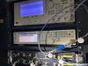
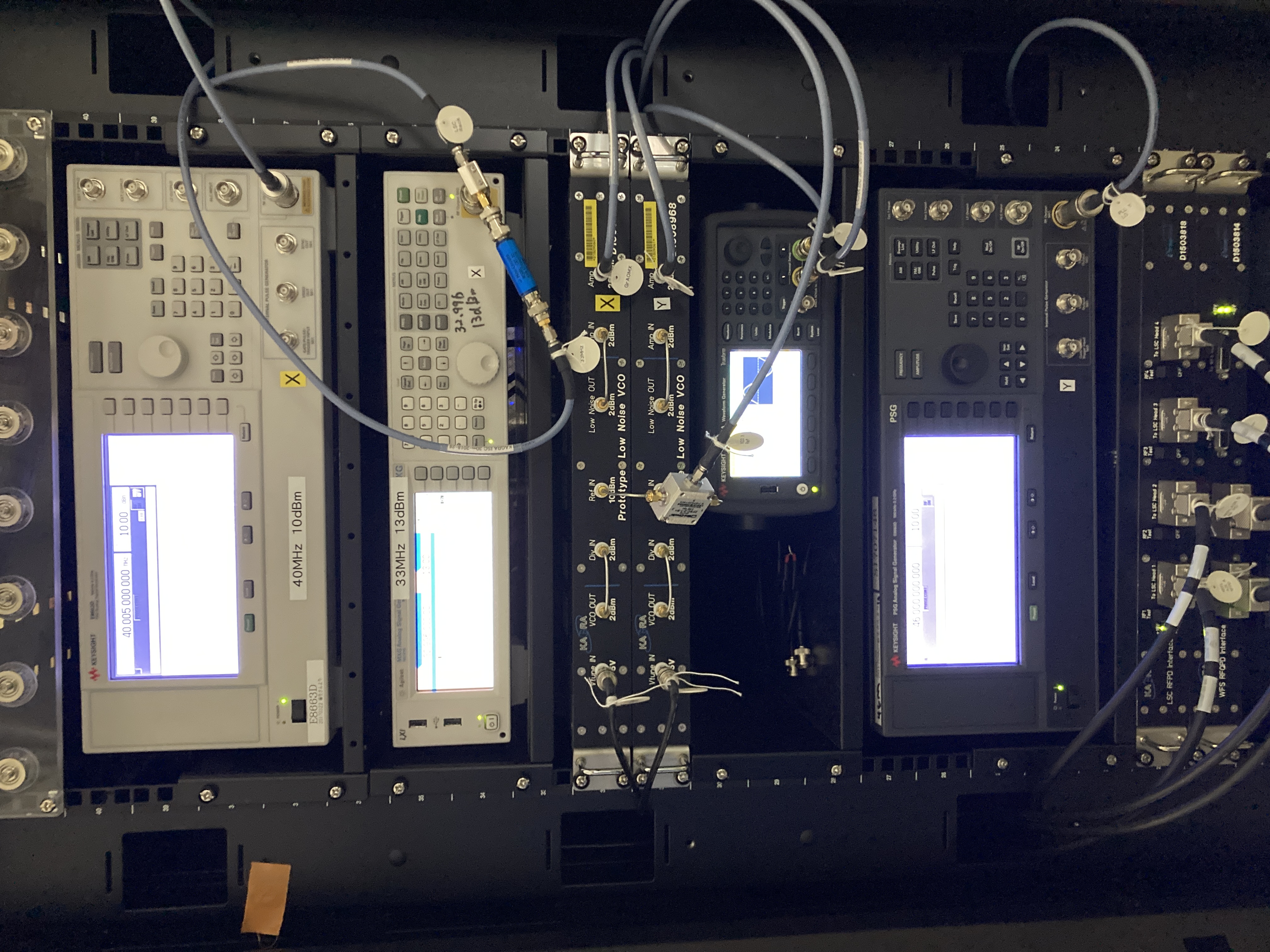
- We found that the signal generator used for LO for PLL X (Keysight E8663D JGW-S1706365) had "ERR" displayed (see Fig. 3, the signal generator on top). To clear this, we had to unplug the LAN cable to set it to local mode (see klog #23718 and klog #23713). The error message was "705, Sweep out of range; Phase Continuous Sweep to 40005000.000 Hz is impossible due to band-cross." Even if clearing the error, no change in the spectra observed.
- We then used the signal generator used for LO for PLL Y (Keysight E8663D JGW-S1707148) for PLL X. The noise level for X matched with Y !!! See black curves in Fig. 2. So the signal generator used for LO for PLL X (Keysight E8663D JGW-S1706365) was the culprit!
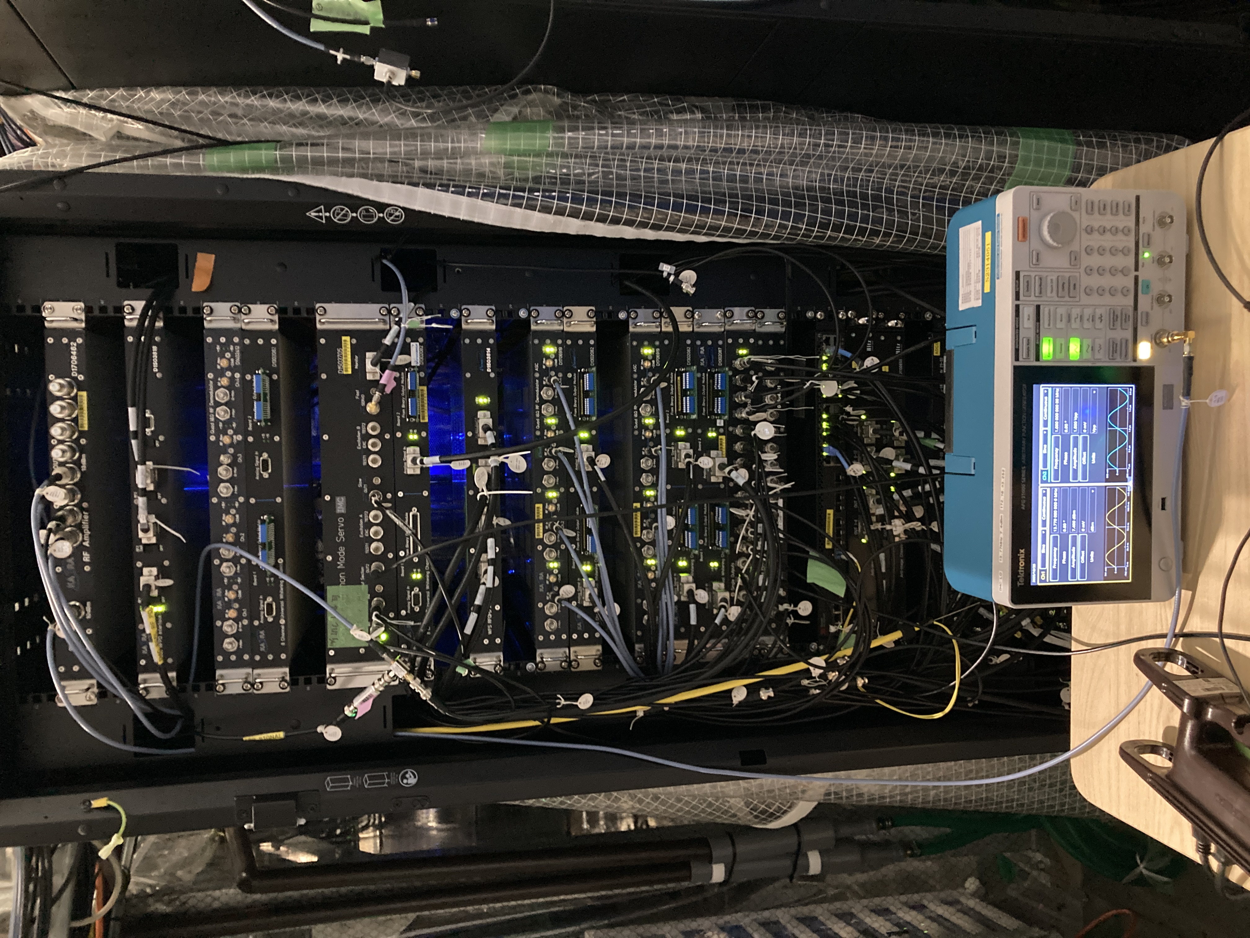
- We found that the signal generator used for IMC modulation was also Keysight E8663D JGW-S2516958 (was sitting between IOO and LSC racks). So, we repurposed this for PLL X, and used Tektronix AFG31022 JGW-S2314951 for IMC. Took the spectra again, confirming that the noise level didn't change with these changes (see right panels Fig. 2).
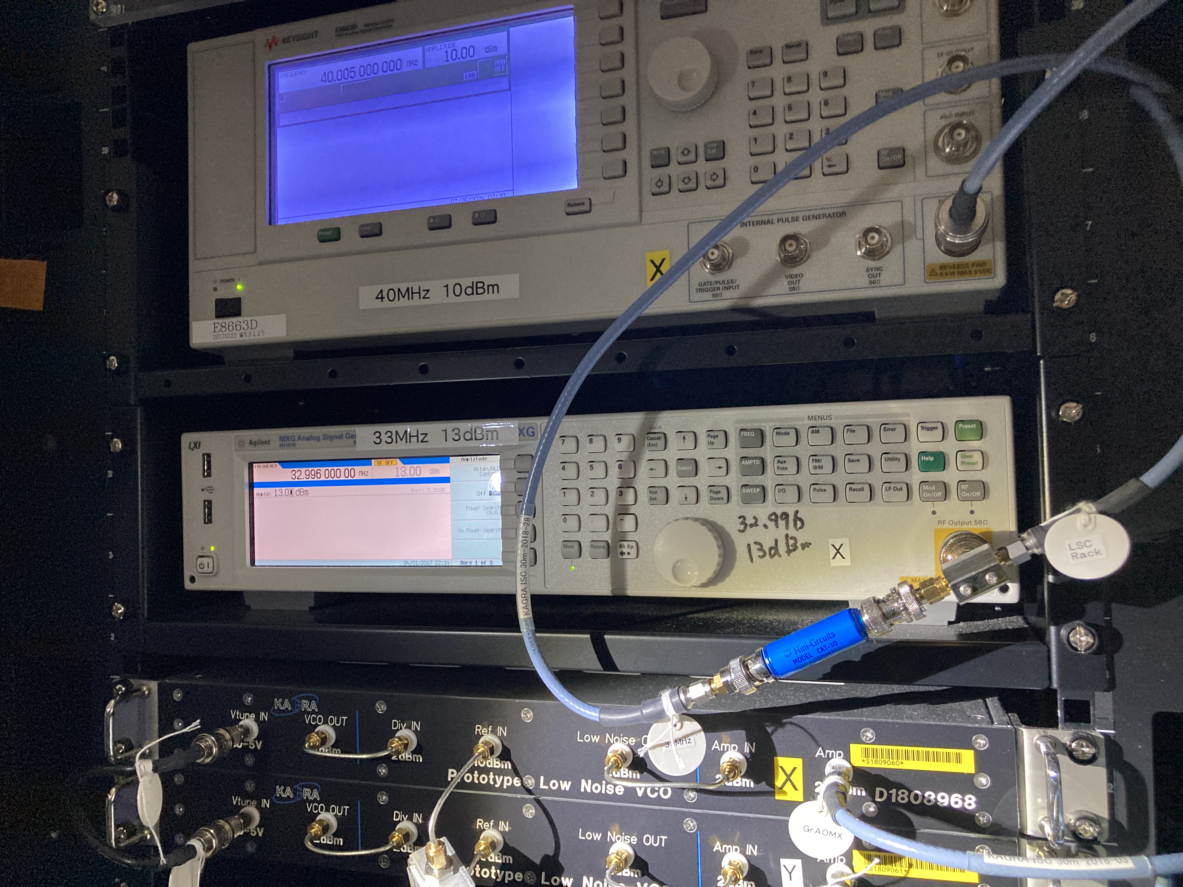
- We have set them so that IP addresses for these signal generators for PLL X and IMC remain the same as previous signal generators. Fig. 4 and Fig. 5 are the photos of the signal generator situations after the work.
| Before work | After work | Setting | |
| IMC modulation | Keysight E8663D JGW-S2516958 | Tektronix AFG31022 JGW-S2314951 | 13.77 MHz, 7.4 dBm |
| PLLX LO | Keysight E8663D JGW-S1706365 (brought to Mozumi electronics shop) | Keysight E8663D JGW-S2516958 | 40.005 MHz, 10 dBm |
| PLLY LO | Keysight E8663D JGW-S1707148 | (same) | 46.000 MHz, 10 dBm |
| Gr X PDH | Agilent N5181B | (same) | 32.996 MHz, 13 dBm |
| Gr Y PDH | Keysight 33600A | (same) | 32.000 MHz, 0 dBm (output 1, for EOM) and 10 dBm (output 2, for IQ demod) |
Discussion:
- The reason why we didn't see the huge noise difference between X and Y in PLL error and feedback signals (klog 35419) is probably because these were dominated by the frequency noise of PROMETHEUS compared with the main laser. PLL LO noise contribution was smaller than the laser frequency noise contribution. PLL LO noise go into this loop as a sensor noise, so we could only see the noise with out-of-loop sensors. The PLL LO noise was flat in frequency, so the small difference could be seen at high frequencies in the PLL loop.
Next:
- Check if IMC noise has not increased due to the signal generator change (unlikely, but just in case).