Komori (remote), Tanaka
## Abstract
We gave up to implementing OMC ASC due to the lack of the reproducibility of the offset in their error signal. The error signals seems to be changed by the beam position on QPD but the beam position control by carrier power seems to conflict the ASC in terms of the PY coupling. So the beam position control turned off in engaging OMC ASC, then the beam position differs whenever the position control turned off because the position which settles down depends on the timing of turning off the control. Therefore, it maybe necessary to keep the beam positon by the control not with carrier but with beacon sideband or RF sideband so that the OMC ASC is engaged without any offset.
## What we did
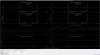
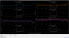
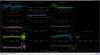
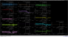
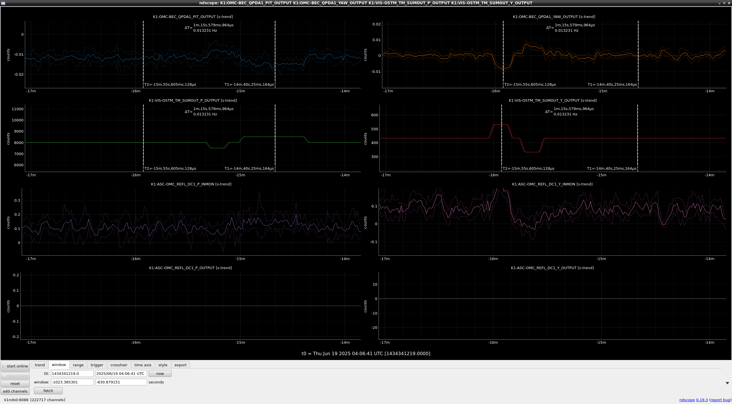
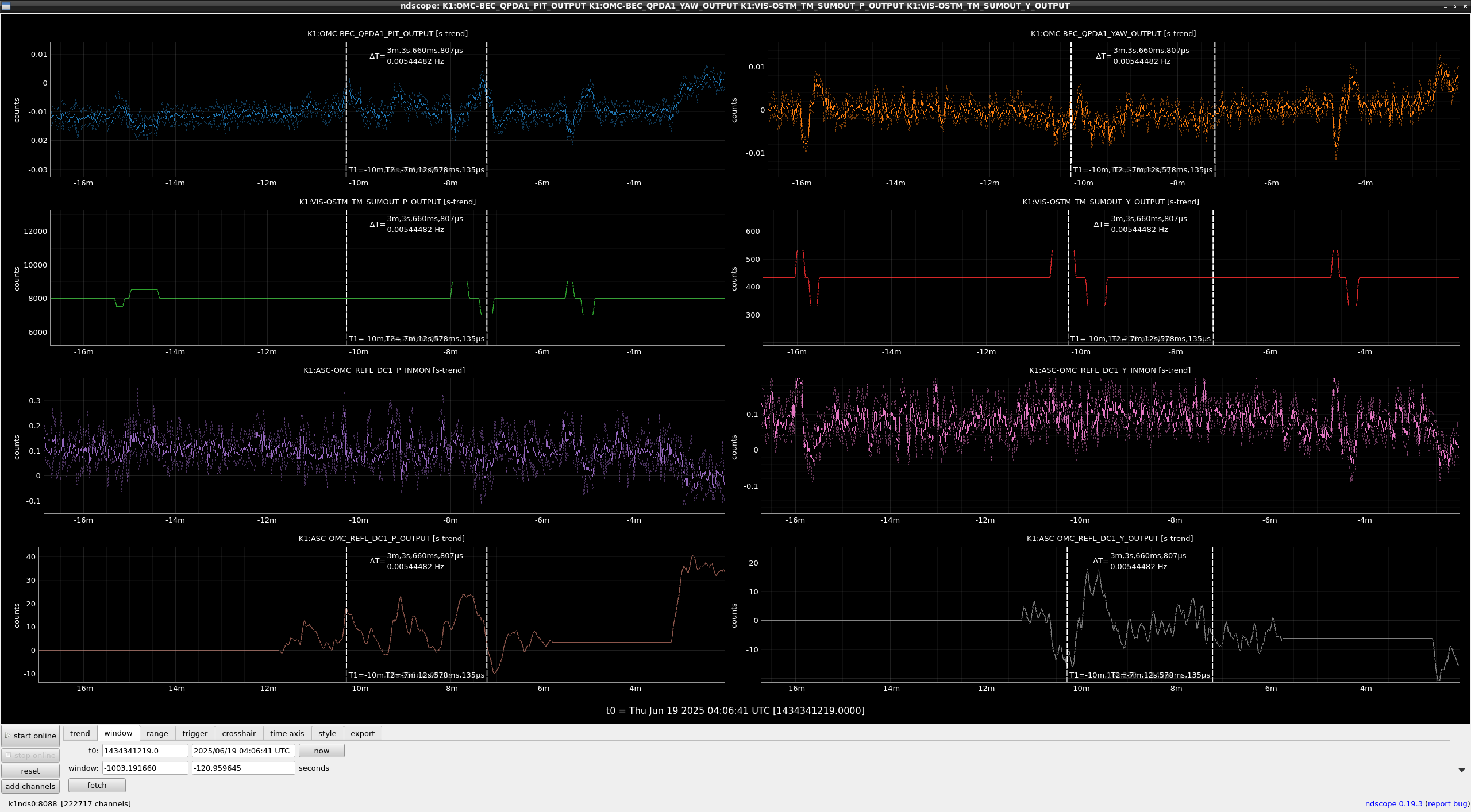
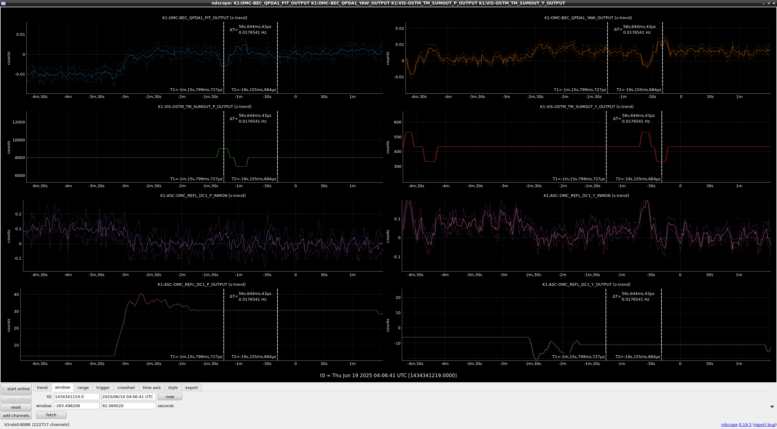
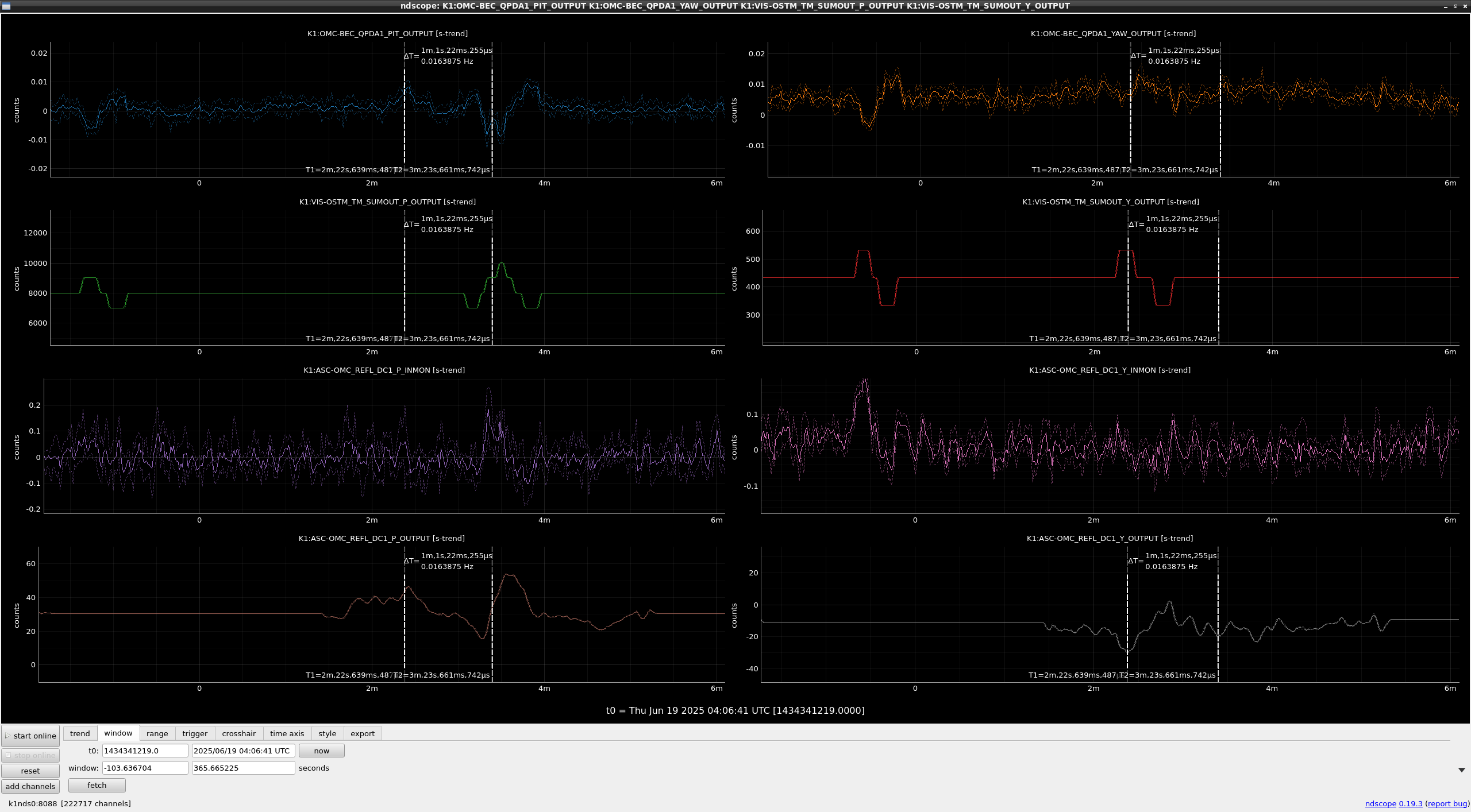
We found that the PY coupling seemed to be caused by the current beam position control on QPDs. Fig. 1 shows the time series of beacon WFS signals, OSTM alignments, QPD1 DC control error/feedback in the PIT/YAW direction. In this state just after the OMC initial alignment by RF sidebands without beam positon control. Fig. 2 shows the ones with engaging beam positon control. According to Fig. 1, when OSTM moved in PIT (YAW), only WFS PIT (YAW) responded. the PY coupling seems to be low. On the other hands, according to Fig.2, although OSTM YAW moved, the WFS YAW did not respond but WFS PIT seems to respond. On the other hand, the YAW beam position control feedback moved, that is, the beam position control cancelled the WFS signal by OSTM movement.
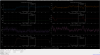
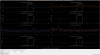
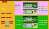
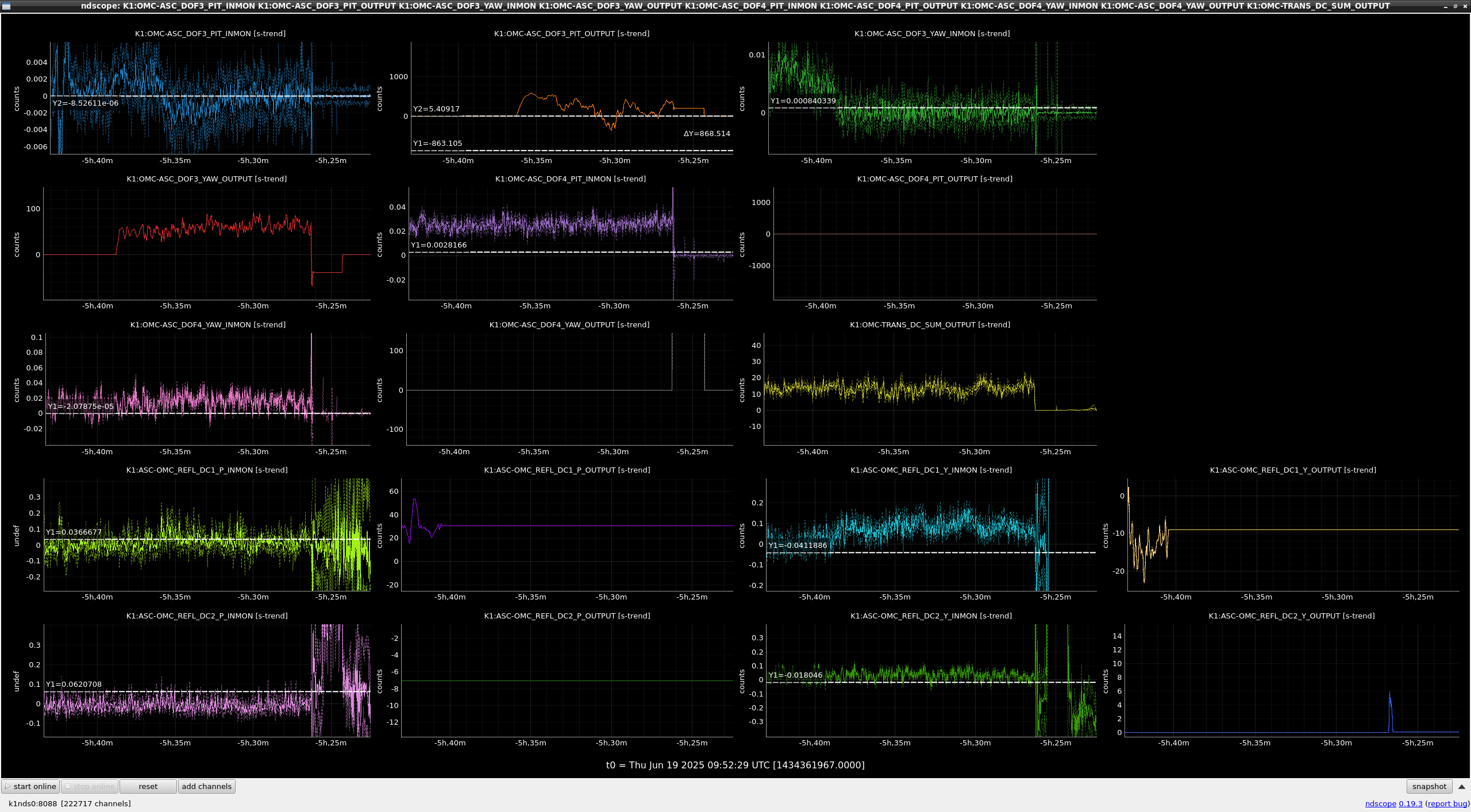
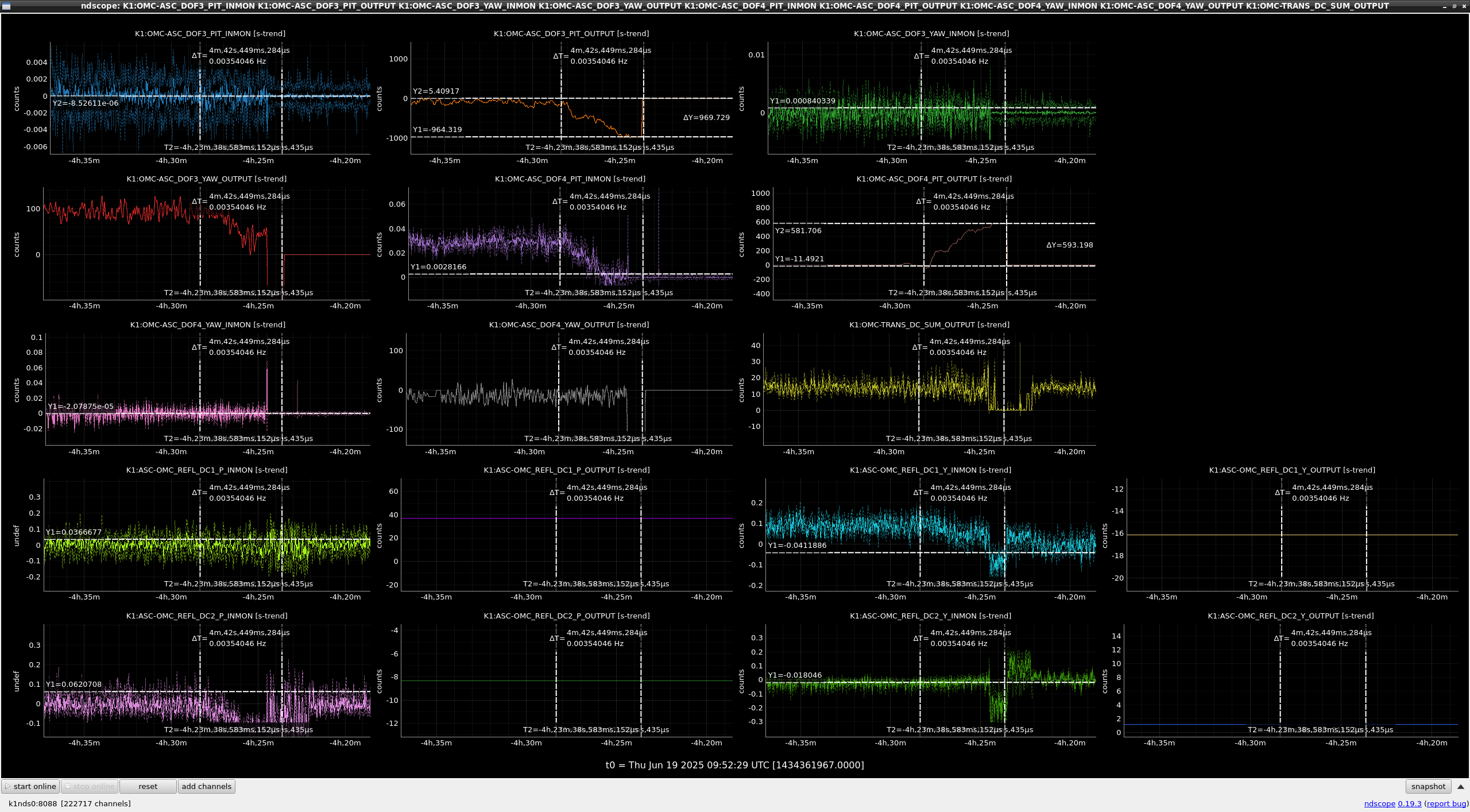
Moreover, we performed this test at the difference beam position. Fig.3 shows the ones without the beam positon control after the beam postion changed. Fig.4 shows the ones with the control. The same phenomena was obsereved even though the beam position changed. Therefore, the PY coupling was caused by the beam postion control and the coupling seems to be independent on the beam positon on QPD. On the other hand, the DC values of theire signals seem to depend on the beam postion.
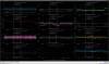
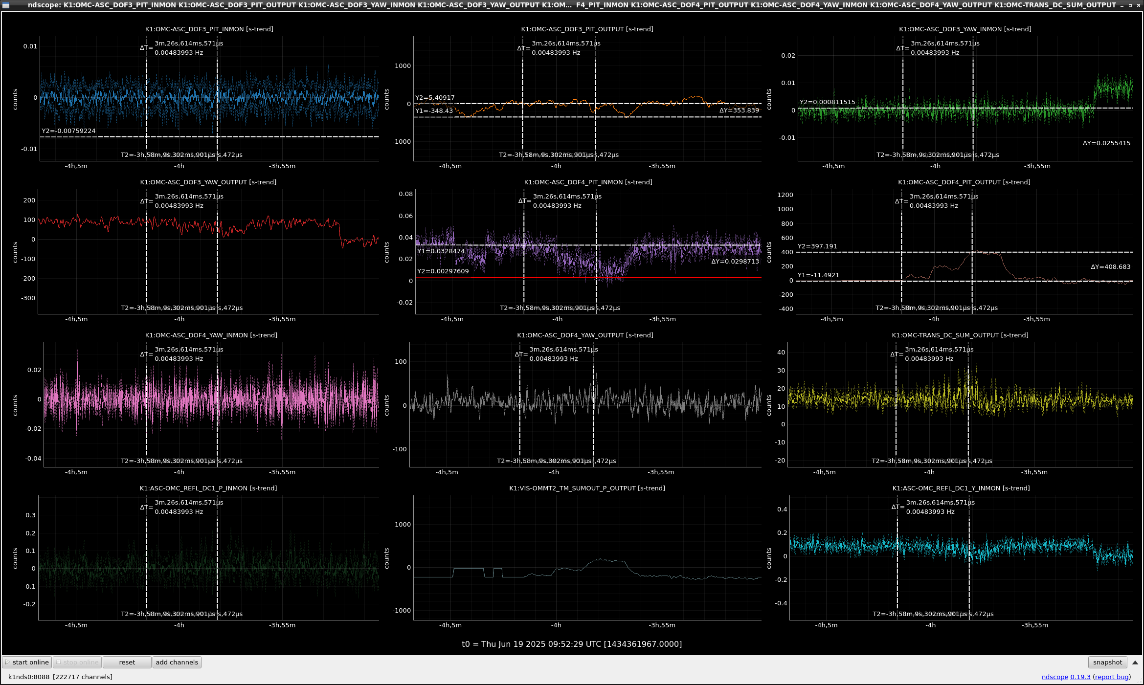
Next, we tried to engage the OSTM controls with beacon WFS1. The engagement seemed to be succeeded (Fig.5). Then we also tried to engage OMMT2 in PIT/YAW with WFS2. As for YAW, the control seems to be stable. As for PIT, however, as the OMMT2 control feedback moves, the OSTM control feedback moves. Fig. 6 shows the timeseris of the error/feedback signals of OMC ASC with beacon. when the OMMT2 feedback (K1:OMC-ASC_DOF4_PIT_OUTPUT) grew to 593 cnt, the OSTM feedback (K1:OMC-ASC_DOF3_PIT_OUTPUT) grew to 970 cnts. So the coupling between OSTM and OMMT2 seems to be large. And also, when OMMT2 control error signal got close to 0, the fluctuation of the OMC TRANS power seemed to increase. Therefore, the OMMT2 error signal has some offset when the alignment is good. Simiraly, OSTM YAW control error signal seems to have some offset.
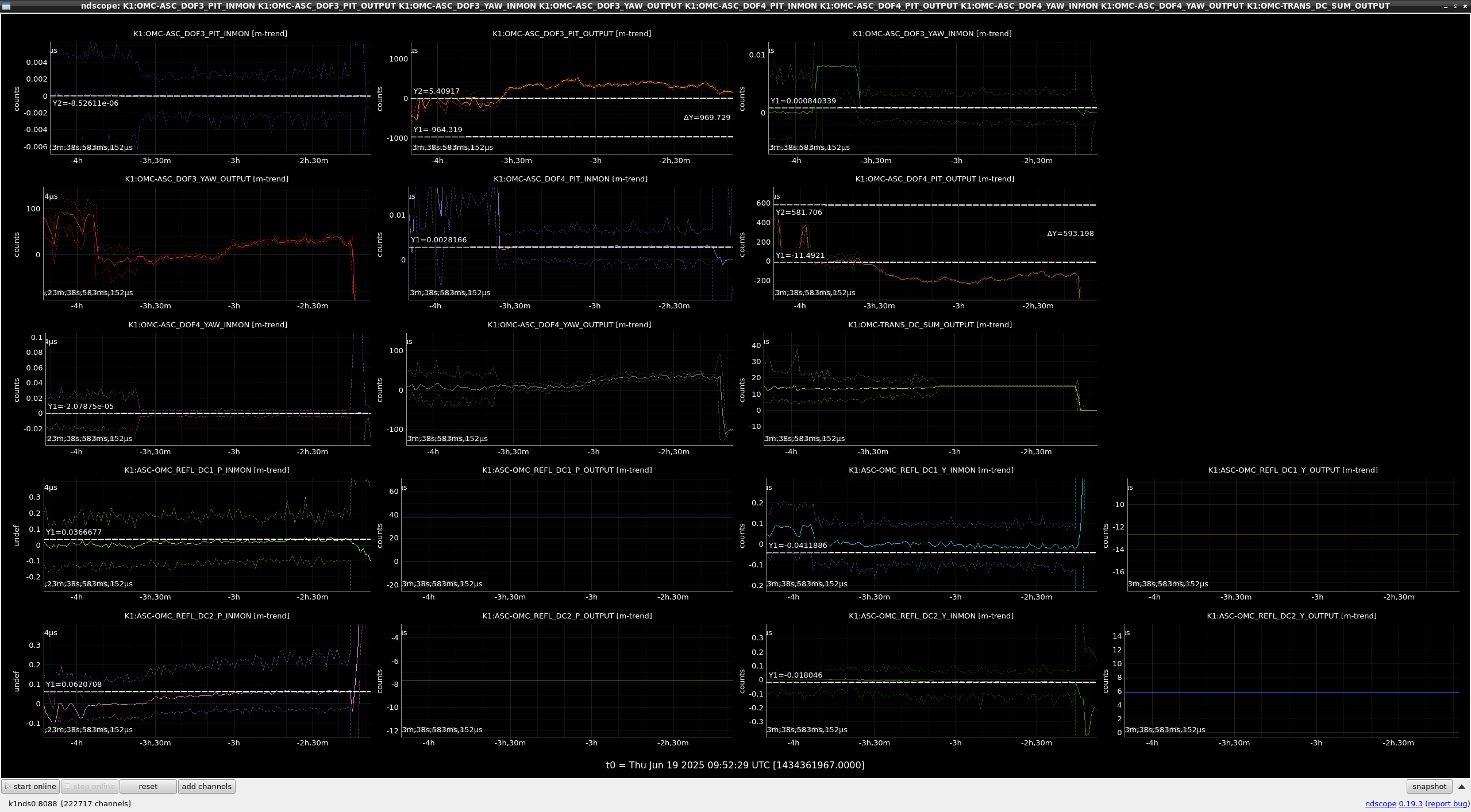
We decoupled OMMT2 and OSTM PIT with the input matrix (fig.7) which is measured previously. we re-engaged OMMT2 and OSTM PIT controls with the decoupled sensors. Fig.8 shows the timeseries after implementing the decoupled matrix. the OMMT2 feedback grew to 410 cnts, but the OSTM feedback did not changed. So the decouple seems to be successful.
Then, we decreased the excitation amplitude of beacon from 10000 cnts to 1000 cnts. According to fig.1 in klog33961, when the beacon excitation is 10000 cnts, there is the large peak in OMC trans. power acompanied with the many sideband peaks. One of possibiities is that these peaks may be the cause of the 300 Hz peak in DARM as reporeted in klog33889. Until now, we used 10000 cnts amplitude to increase the S/N ratio of WFS signals. If we could reduce the amplitude, we can use the beacon without the degradation of the sensitivity. So we tried to reduce the amplitude from 10000 cnts to 1000 cnts. Before changing the excitation amplitude, we stopped the ASCs for OSTM YAW and OMMT2 PIT because they have some offset and the offset value should be changed by the excitation amplitude. After changing the amplitude, we confirmed their offset reduce to 1/10, then we re-engaged the controls. the control seems to be stable. So we locked IFO with DC readout. In this state, IFO could be kept at least 30 mins until the earthquake lost the lock (Fig.9).
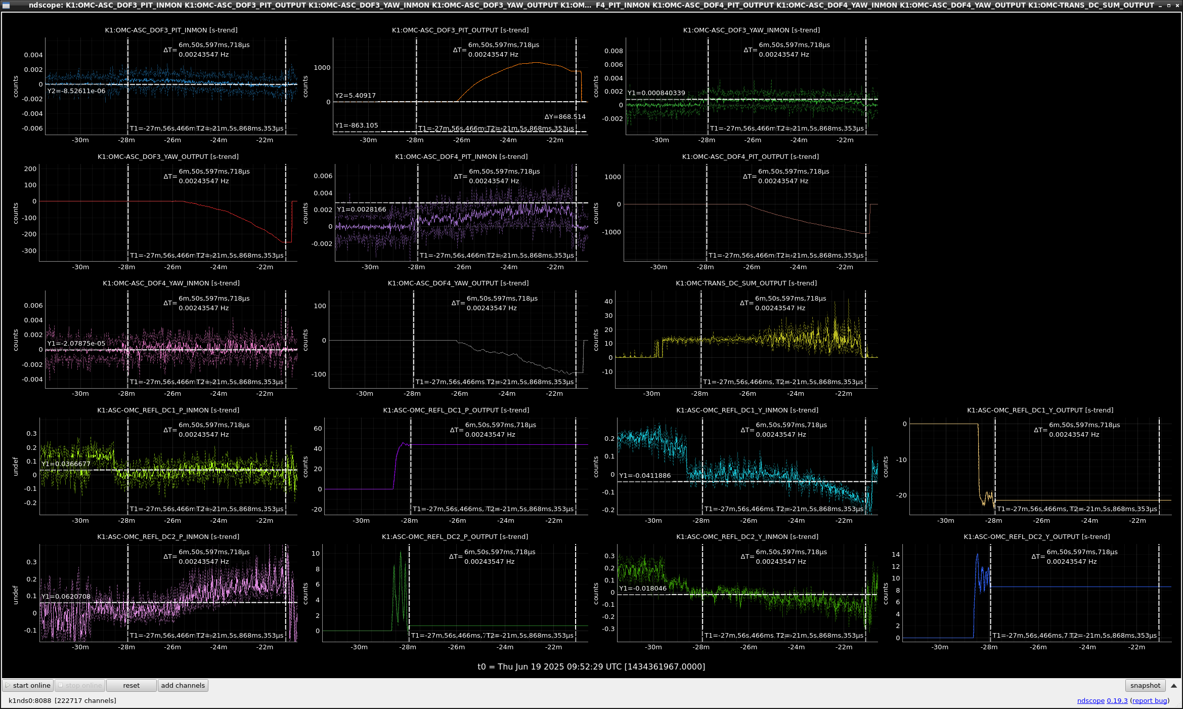
At last, we checked the offset values have reproducibility in every locks. (This is the most important point). After relocking OMC from the last lock loss. Fig.9 shows the timeseries after relock OMC. the left cursor in fig.10 indicates the timing when the beam postion control turned off. At that timing, the offset in OMMT2 PIT error signal (K1:OMC-ASC_DOF4_PIT_INMON) was difference from the one of the last lock.Then we tried to engage with the previous offset values. However, as the control went to each setpoints, OMC TRANS power fluctuated a lot. This indicates the alignment got worse. Therefore, the offset value is not reproducibility in every lock, unfortunately.
One of possibilities that the offset varies in every lock is that every beam position differs after the beam positon control is turned off. As mentioned above, the DC value of the signal depends on the beam postion. It may be necessary to bring the same positon every time in order to obtain the reproducible setpoint, that is, 0 setpoint.
Anyway, I gave up to implement OMC ASC for this observation.