Reports 1-1 of 1 Clear search Modify search
MIF (General)
kentaro.komori - 2:42 Thursday 24 April 2025 (33535) Print this report
Revisiting BPC tuning

[Tanaka, Ushiba, Komori]

Abstract:

We have started fine-tuning the beam spot position on the input test masses.

Details:

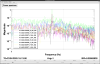
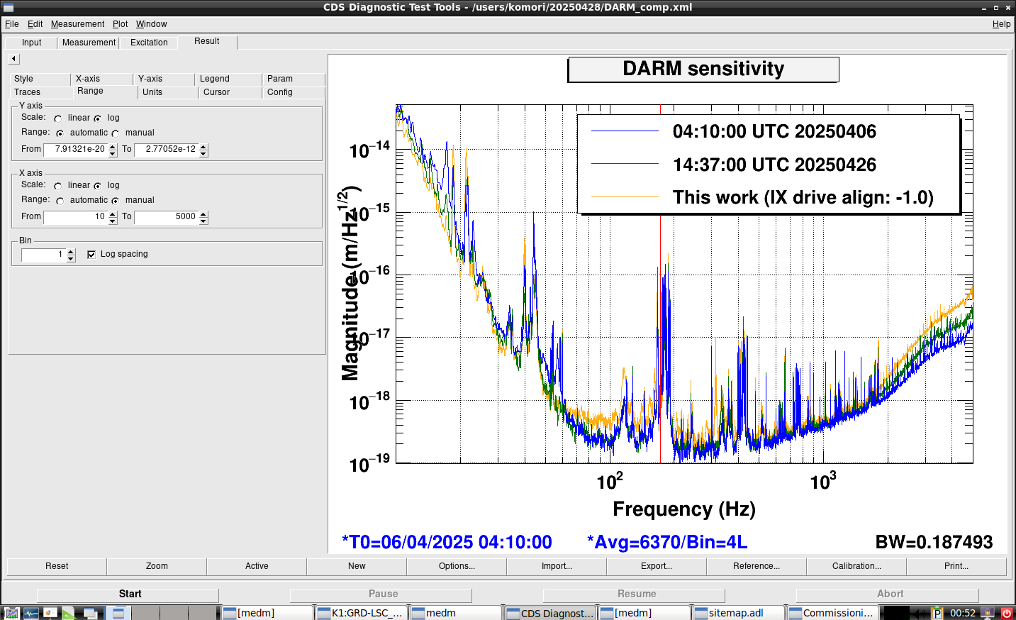
The current DARM noise around 100 Hz may originate either from jitter coupling caused by birefringence in the input test masses (ITMs) or from unexplained interference observed in the REFL PDs.
In both scenarios, adjusting the beam spot position on the ITMs could help mitigate the noise—either by targeting beam spots with lower birefringence or by approaching the condition of a critically coupled cavity.

In previous attempts, we tried to shift the beam spot by adding offsets to the BPC, but lock loss occurred before we could observe any meaningful change in the DARM sensitivity.
Possible causes included reduced PRCL control gain and misalignment to the OMC.
To address these issues, our new strategy is to apply BPC offsets during 10 W RF locking, perform initial OMC alignment with RF sideband, and then transition to the observation state.

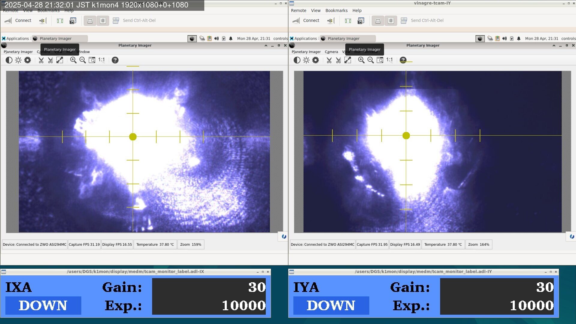
As a first trial, we applied a negative IX BPC pitch offset to move the beam spot closer to the center of IX, which is favorable for reducing pitch suspension thermal noise.
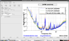
With an offset of -3.0 (corresponding to +3.0 in IN1), the X-arm transmission increased by 1–2%.
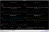
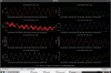
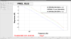
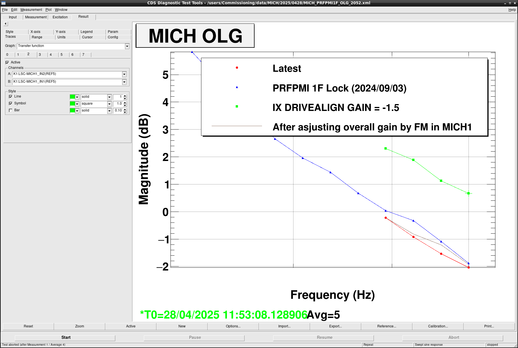
We also measured the PRCL open-loop transfer function at the same offset and found that the gain increased by approximately 1-2 dB.
This suggests that the optical loss at this alignment point may be lower than in the conventional configuration.
This offset corresponds to approximately -0.5 urad in PR3 pitch, which implies a beam spot shift of roughly 0.5 mm—still relatively small.

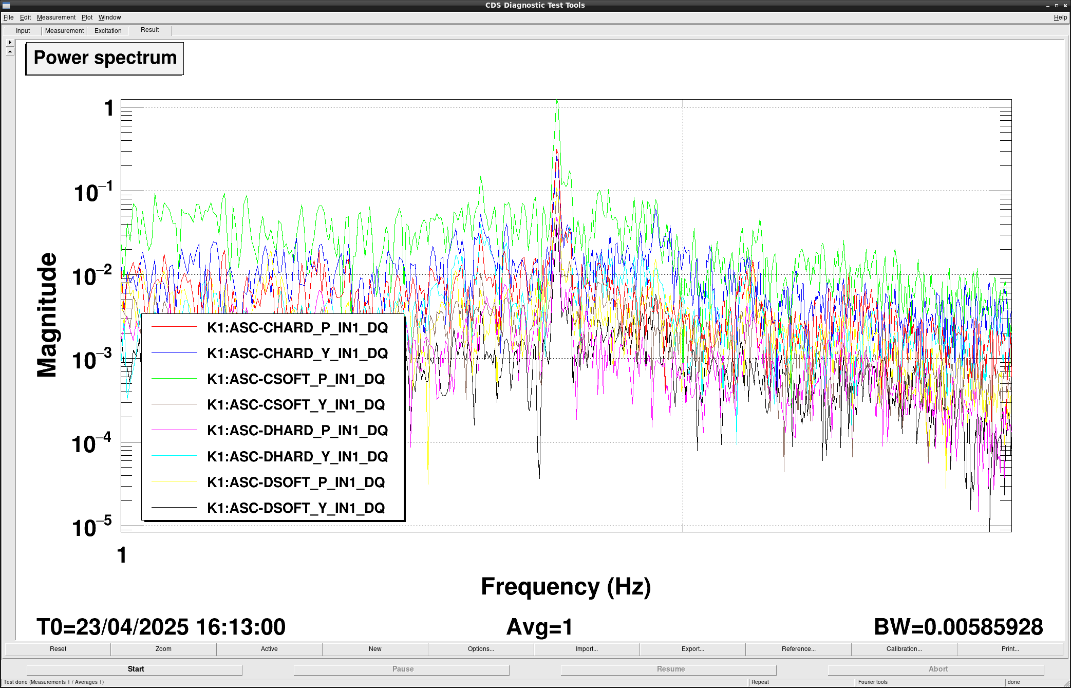
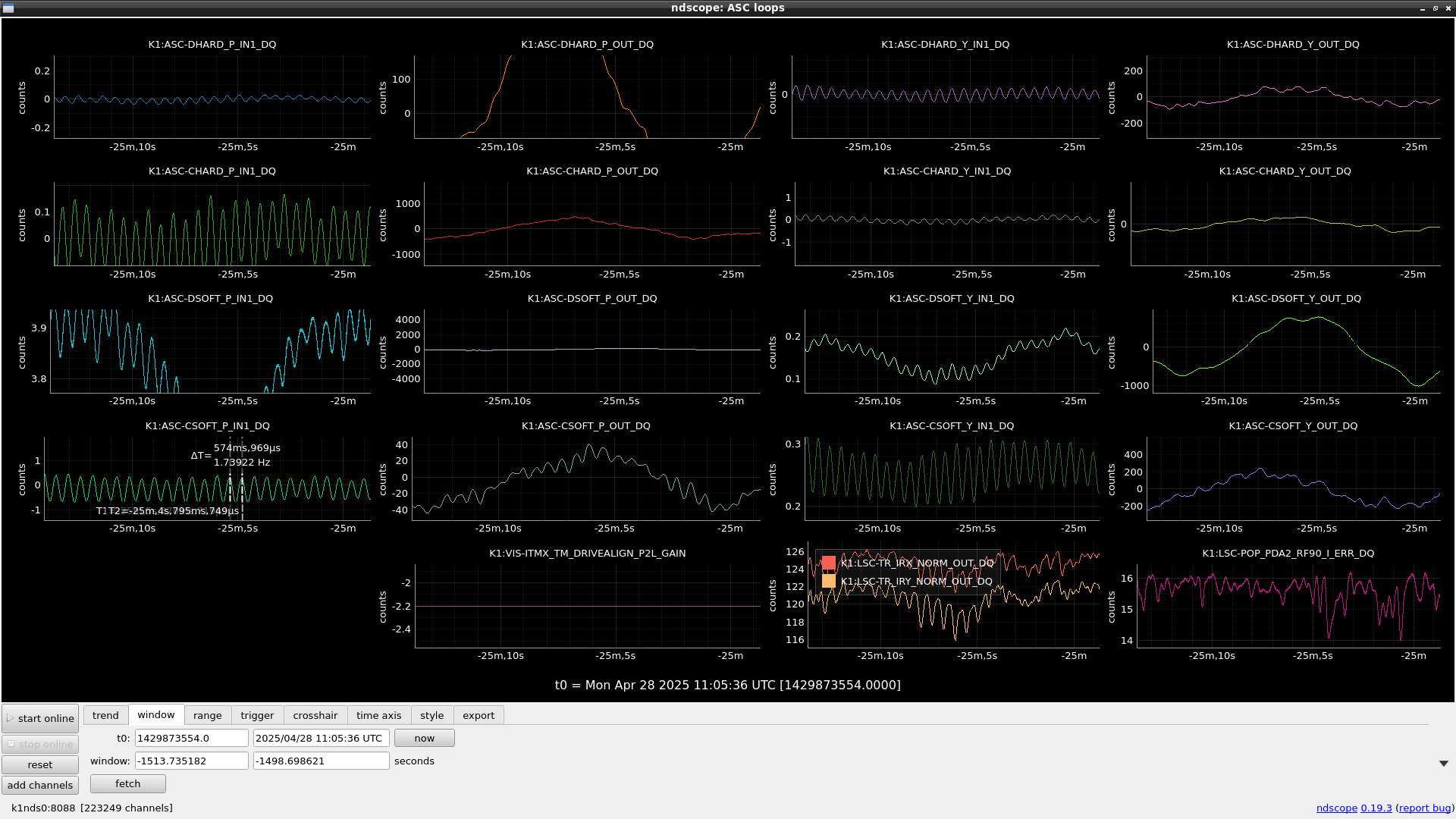
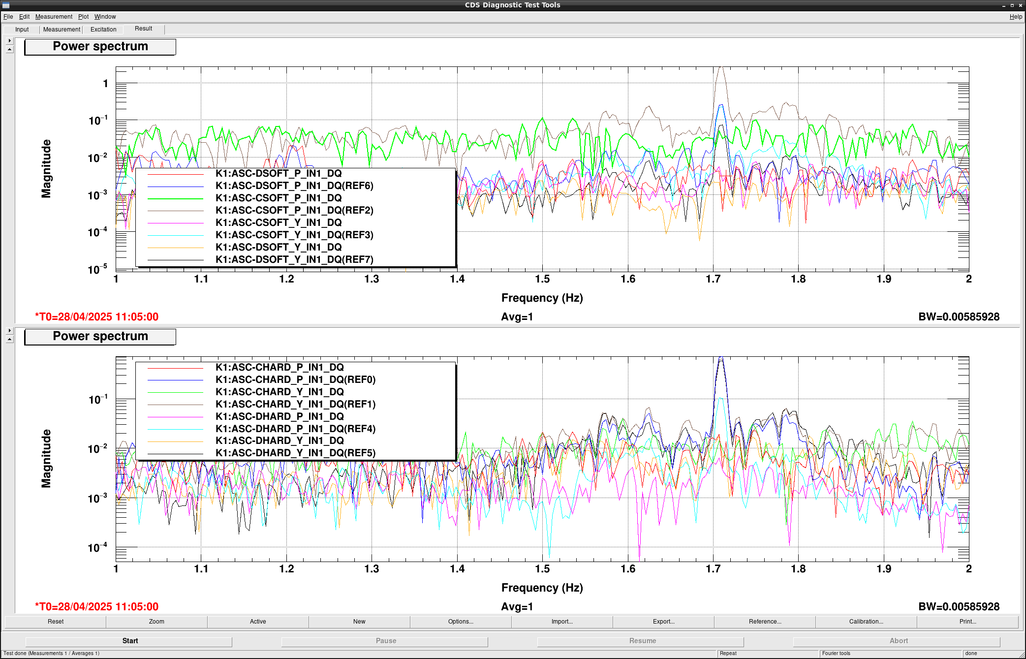
We then applied an offset of -5.0, but the arm ASC likely began to oscillate around 1 Hz, leading to IFO unlock.
After recovery of 10 W RF locking, I temporarily reduced the DHARD and CHARD gains by half, but the same oscillation reoccurred.
We will need to address this issue in order to enable further beam spot adjustments.

Comments to this report:
kentaro.komori - 14:03 Monday 28 April 2025 (33569) Print this report

[Tanaka, Komori]

Abstract:

We shifted the IX beam spot by approximately 10% relative to the original miscentering, but the DARM sensitivity did not change.
We plan to address the oscillation issue and attempt a more significant beam spot adjustment.

Detail:

This is a report on the commissioning work related to BPC, conducted last Friday and Sunday.

Following the earlier post where we brought the IX beam spot closer to the center, we investigated which feedback loop began oscillating.
The attached figures show each arm ASC error signal (Fig. 1) and the test mass witness channels (Fig. 2).
The oscillation amplitude was largest in CSOFT P and EY P signals, respectively.
Therefore, we attempted to adjust the CSOFT P gain before the oscillations started, but this did not change the onset timing of the oscillations.

Given this, we decided to tentatively stop moving the beam spot at the point where oscillations did not occur and checked the DARM sensitivity.
We also found that adjusting the drive input matrix value for P2L in the IX BPC was more effective than simply adding an offset to the BPC error signal.
Specifically, we changed the P2L drive matrix value from -2.5 to -2.2, and checked the DARM sensitivity.
However, the sensitivity remained very similar after this adjustment.

So far, the beam spot has only been shifted by about 10% compared to the original miscentering.
We plan to tackle the oscillation issue next and attempt a more substantial beam spot change.
A potential reason of the oscillation might be couplings to other ASC degrees of freedom by changing the beam spot at the transmission QPDs for both arms.

Images attached to this comment
kenta.tanaka - 23:59 Monday 28 April 2025 (33588) Print this report

[Komori, Tanaka]

## Abstract

We tried to shifted an IX beam position by tuning BPC offset. A 1.71 Hz oscillation reported by the original post seems to be caused by the radiation pressure in the tuned cavity. We can avoid the oscilation after engaging DARM offset. On the other hand, we found that MICH overall gain increased by shifting beam position. We are not sure the reason for now. We can reduced the DRIVEALIGN value to -1.0. However when the value got lower than -1.0, ASC started to oscilate at 0.6 Hz. We need more investigation.

## What we did

  • Before shifting the IX beam position, we modified the Q value (30 -> 10) and depth value (30 dB -> 60 dB) of notch filter for 1.71 Hz in ARM ASC loops to avoid the 1.71 Hz oscillation which occures when the DRIVEALIGN GAIN got closer to 0 from -2.2 as reported by the original post (fig.1).
  • Then, we tried to shifted the beam position by tuning BPC offset with PRFPMI 10W DC lock. Actually, we tried to close the value in IX DRIVEALIGN gain from -2.5 to 0. In this state, the 1.71 Hz oscillation didn't occur even though the gain was below -2.2.
  • However, When the value got -1.5, Lock loss happened due to the OMC PD saturation by 18.8 Hz oscillation (maybe MICH?) (fig.2). At least, ASC and BPC loops seems not to oscillate at that time.
  • Then, we restored the DRIVEALIGN gain to -2.5 and locked PRFPMI with 10W RF. Then, we retried it. But, 1.71 Hz oscillation occured when DRIVEALIGN value got lower than -2.2 even though the notch filters were not restored. On the other hand, we found that ASC feedback signals seemed to be not oscillated at 1.71 Hz largely (fig.3). From this and the fact that the 1.71 Hz oscilation did not occur in DC readout, we considered the oscillation occured in the case of the tuned cavity, so we can avoid the oscillationg by engaging DARM offset. we tried this hypothesis by reducing the DRIVEALIGN gain from -2.5 after engaging DARM offset. Then, the oscillation was not happened even though the gain value got below -2.2.  Fig. 4 shows the spectra of ASC error signals before and after engaging DARM offset, the REF labeled spectra are without DARM offset, the others are with DARM offset. the 1.71 Hz peaks disappeared in the spectra with DARM offset. This indicates the 1.71 Hz oscillation seems to be caused by raditation pressure from intra-cavity light. We are not sure which dofs the pressure pushes, (Length or Alignment) for now.
  • Then, the DRIVEALIGN gain reached -1.5 in the RF lock. We measured the OLTFs of MICH and PRCL in this state. Fig.5 and 6 show the result, respectively. PRCL gain seems not to changed but MICH gain seems to become larger to ~2.5 dB.  This is maybe reason why the 18 Hz oscillation was happened in the DC lock. In this time, we implemented the gain -2.5dB in FM1 of MICH1 to compensate this gain increasing. Then, we continued to shift the beam position.
  • We could reach to -1.0. We set -0.5 and after a while, ASC started to oscillate at 0.6 Hz. Since the MICH gain increased, we considered 17MHz sideband signals increased. So we considered this oscillation caused by increasing DHARD gain like the MICH case. I reduced the gain the DHARD loop but the oscillation was not stopped. Moreover, I reduced the other gains but the situation was not changed. Finally, PRFPMI lock was lost.
  • Tonight, we stopped the trial. Fig. 7 shows the IX/IY beam position before the trial and Fig.8 shows the beam positions after the trial. We need to check the OLTF of ASC loop and want to try DC readout and check the DARM sensititvity.

## Note

We restored the DRIVEALIGN value to -2.5 because incrasing 10 W seems to fail when the value was still -1.0. I left IFO in the PRFPMI RF lock state and hope that ASC restores the alignment before the trial.

Images attached to this comment
kentaro.komori - 3:14 Tuesday 29 April 2025 (33589) Print this report

After this work, I succeeded in achieving the DC readout with the drive align for IX of -1.0.
Unfortunately, the DARM sensitivity got worse.
The detail will be reported later.

I ieft the IFO to be 10-W RF locked state with the drive align of -2.5, and ASC offset to be zero.
Please use the IFO freely.

kentaro.komori - 8:01 Wednesday 30 April 2025 (33603) Print this report

As reported in the original post, we encountered a 1.7 Hz oscillation, even though a notch filter appeared to sufficiently suppress this frequency in the feedback signal. 
We found that this oscillation does not occur during DC readout, suggesting that it originates from a radiation pressure effect, and that cavity detuning may have introduced additional stability—possibly due to a small optical spring.

To mitigate this issue, we followed the procedure below and successfully reached the observation state with an IX drive alignment value of -1.0:

  • Reached the “Engaging DARM offset” state

  • Set the IX drive alignment to -1.0 and waited for BPC stabilization

  • Performed initial OMC RF alignment

  • Reached DC readout

The resulting DARM sensitivity is shown by the orange line in the attached figure.
Although the sensitivity improved at low frequencies, it degraded at mid and high frequencies.
We attempted to recover sensitivity by adjusting the INP2 and PRC2 offsets, but the improvement was limited.

We then restored the IX drive alignment to -2.5, and the sensitivity returned to the previous level (blue and green lines in the figure), without needing to redo the OMC RF alignment.

A possible cause of the degraded sensitivity with the -1.0 alignment is reduced common-mode rejection.
In fact, frequency noise increased, and the arm transmission at both ends became more asymmetric than usual.

The IX beam miscentering was previously measured to be approximately 1 cm at a drive alignment of -2.5.
Therefore, with a drive alignment of -1.0, the miscentering should be around 4 mm.
Although this represents a noticeable shift, it did not improve sensitivity—indicating that this direction of beam spot adjustment is likely unfavorable.

Next, we will evaluate the sensitivity after shifting the beam spot further toward the edge, using a drive alignment value of -3.0 or more.

Images attached to this comment
Search Help
×

Warning

×