Aso, Ushiba, Tanaka
We found some issues between IFI and PRM as below.
### fringe-like signal in REFL PDs even though all Type-As misaligned
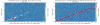
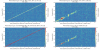
At first step, we confirmed whether the misalignment amount of TypeAs in the MISALIGNED state is enough or not. This morning, Ushiba-san pointed out that the yesterday's misalignment amount of (at least) ITMY got smaller than usual because of lower actuator efficiency by inserting the resistor in TM stages (klog33426), that is, the fringes in REFL PDAs were caused by this unintentional PRY cavity. So we increased the misalignment amounts of both ITMs by rotating BF stages in Yaw direction to ~3 mrads. However, the fringes still remained in this state. Then, we moved each ITM to the L direction one by one to check whether ITM misalignment mount. The fringe-like signals were not changed. This indicated that both ITMs were not cause of the fringe. Similarly, we moved BS and the fringe was not changed. However, we moved PRM or IMMT1 (fig.1, 2) and the fringe responded in either case. Therefore, there seems to be a kind of fabry perot cavity somewhere between IFI and PRM.
We suspected the cavity was consisted of one of IFI component and PRM. In this case, we expected that the fringe got smaller if we tweaked the alignment by changing the beam position on IMMT1. We tried it by sweeping the setpoint of IMMT1 TRANS QPDA1 from -0.5 cnt to 0.5 cnt in each P and Y direction. According to QPDA2, which has almost same gouy phase as QPDA1, the calibration factor from cnts to mm on QPD is 1.6, so we tweaked the beam position from +/- 0.8 mm in both direction. Whenever tweaking the beam position on IMMT1, we aligned IMMT1 and IMMT2 to keep the beam position on PRM to keep the input alignment for PRM. Unfortunately, the fringe seems not to be changed by changing the beam postion (fig.3).
For now, we are not sure that hom much this fringe-like signal affect the current DARM sensitivity. But, we must remove it untill the future observation.
### Issue of bumps in REFL PDs with PRM single-bounced beam
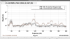
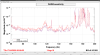
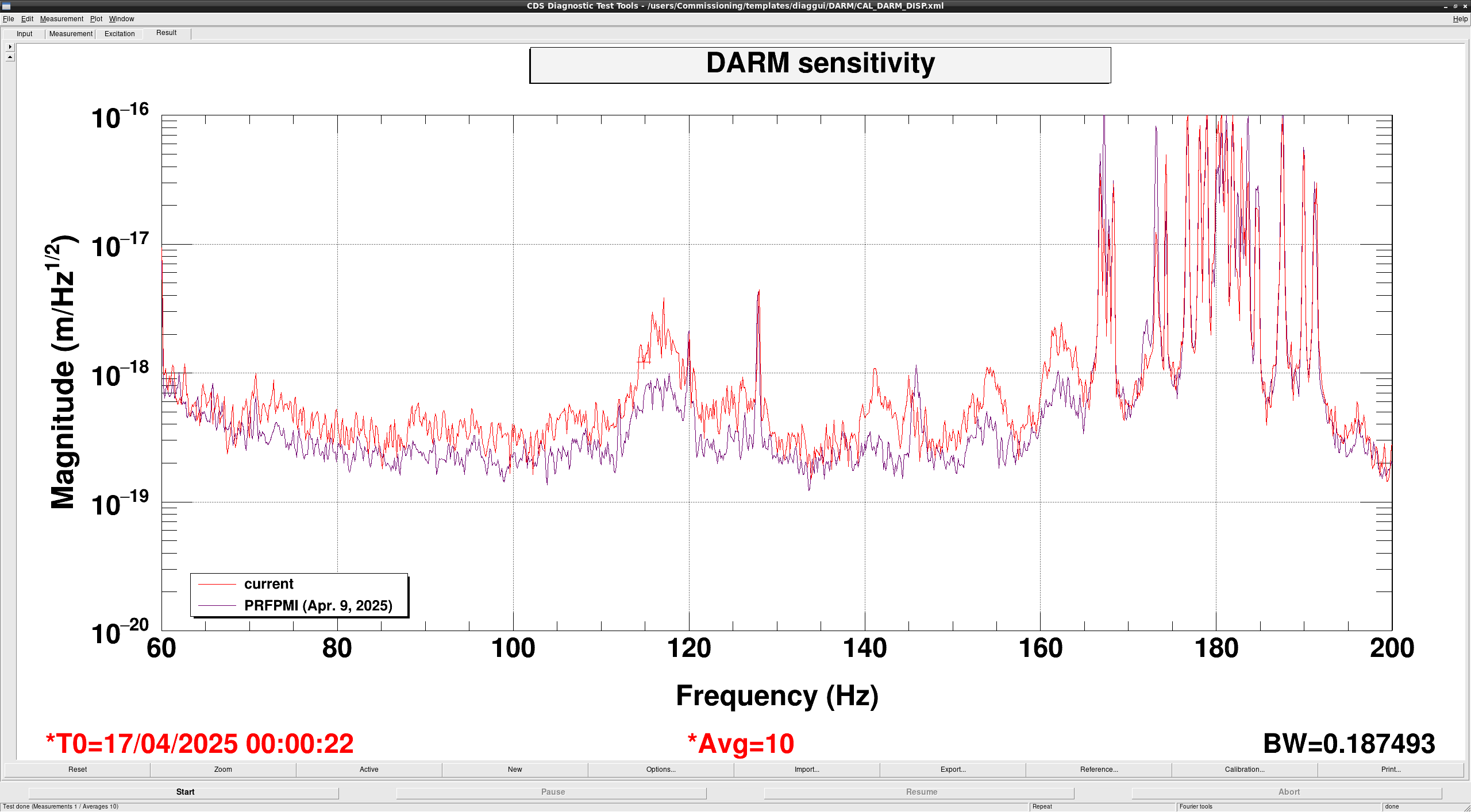
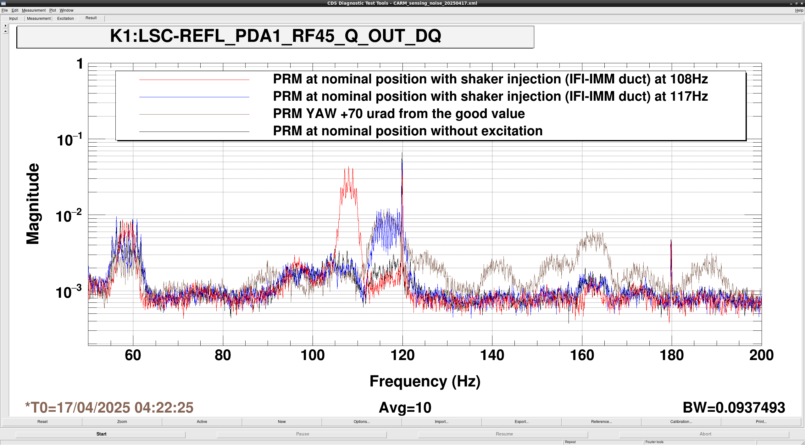
During above investigation, we found that the 117 Hz bumps in REFL_PDA1_RF45_Q_OUT_DQ with PRM single-bounced beam appered just by misaligning PRM. Fig.4 shows the spectra of REFL_PDA1_RF45_Q_OUT_DQ, when the PRM alignment is nominal (black) and when PRM misaligned to 70 urad in Yaw (brown). This time, we increased the power on REFL_PDA1 from ~10 mW to ~ 30 mW. As you can see, the bump around 117 Hz grew up. Furthermore, other bumps appearded around 140 Hz and around 160 Hz. This bump frequency and shape seem to be consistent with the ones in the DARM sensitivity around these frequencies in this morning (fig.5). On the other hand, the fringe in PDAs got smaller at that time. Therefore, the fringe may not be related to these bumps. This indicates that the scattered light somewhere between IFI and PRM couples to DARM for some reason and the coupling ratio depends on the alignment of the input axis to PRM.
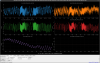
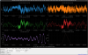
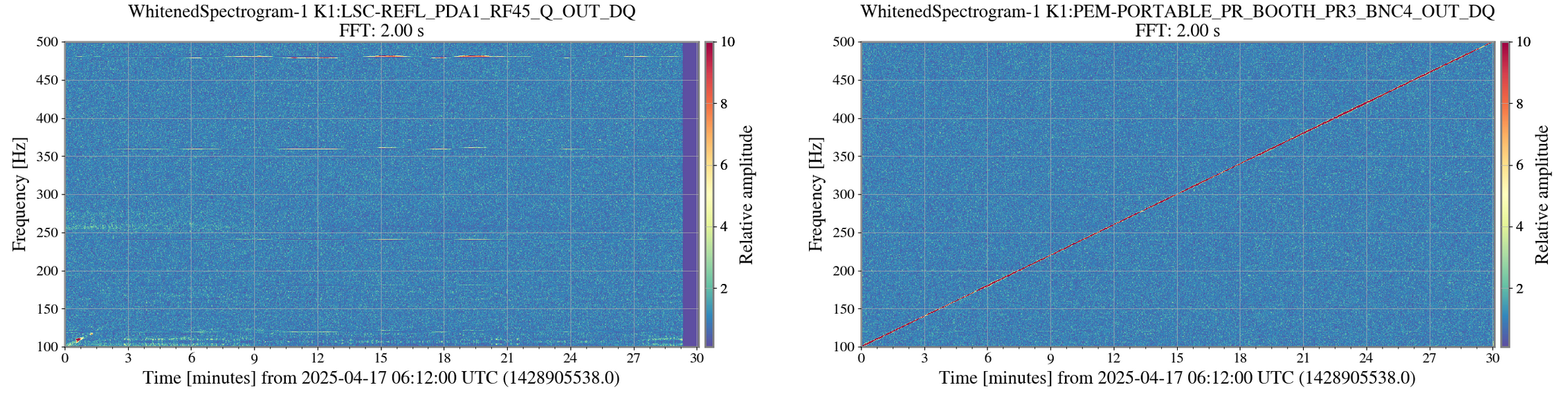
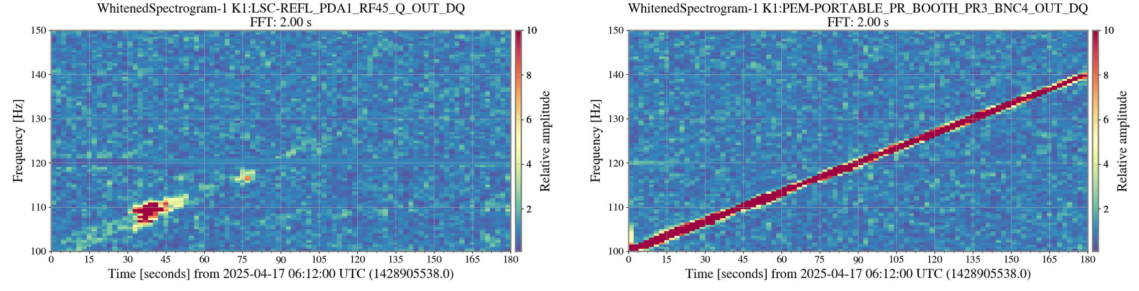
Next, in order to check the effect of the scattered light, we performed the shaker injection with the shaker on the duct between IFI and IMM chambers (K1:PEM-EXCITATION_MCF0_RACK_12_EXC), according to klog33360. We tried to excite the duct at some frequencies, then REFL_PDA signals responded. So we sweeped the excitation frequency from 100 Hz to 500 Hz for 30 mins. This time, the excitation amplitude was 10 cnts. Fig.6 shows the whitened spectrograms of the CARM in-loop sensor (K1:LSC-REFL_PDA1_RF45_Q_OUT_DQ) and the accelarometer next to the shaker (K1:PEM-PORTABLE_PR_BOOTH_BNC4_OUT_DQ) by Pastavi. As for REFL_PDA1, there are some responces just for first 3 mins. Fig.7 is zoomed up one for the first 3 min. As you can see, there seems to be the strongest responce when the excitation frequency is around 108 Hz, and there seems to be the second strongest responce when the exc. frequency is around 117 Hz. So, we excited at these frequencies, one by one and checked the spectrum of REFL_PDA. fig. shows the results. red is the spectrum when the excitation frequency is 108 Hz, and blue is the one when the exc. freq. is 117 Hz. the bump appear around the related frequency.
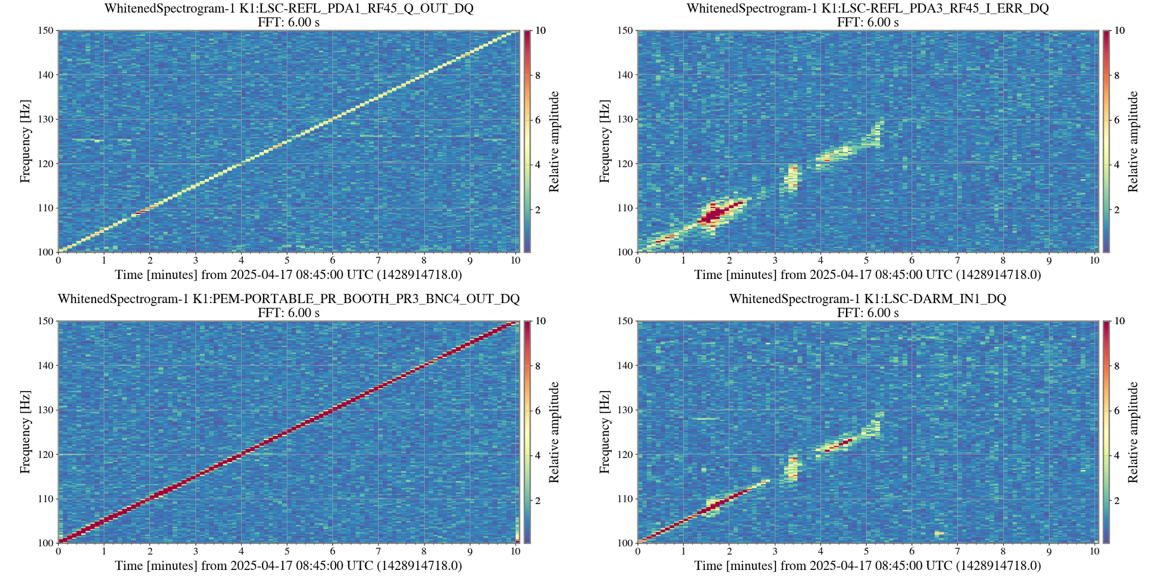
After that, we locked PRFPMI and then performed the injection with the same procudure, The sweep range of frequency was from 100 Hz to 150 Hz for 10 min. Fig.8 shows the whitened spectrograms of CARM in/out -loop sensors (K1:LSC-REFL_PDA1_RF45_Q_OUT_DQ, K1:LSC-REFL_PDA3_RF45_I_ERR_DQ), accelarometer (K1:PEM-PORTABLE_PR_BOOTH_BNC4_OUT_DQ), and the DARM error signal (K1:LSC-DARM_IN1_DQ). There are resoponces around 108 Hz and 117Hz in PDA3, at the same time, there is the frequency broad responce around 108 Hz and 117 Hz in DARM_IN1. This means that the vibration around the duct in these frequency region may have some effect in DARM.
On the other hands, other frequency region, for example 140 Hz or 160 Hz seems to be not responded. These frequencies may be unable to excite from the shaker on the duct. So we wanna use the shakers at the other points next time.


