Komori, Tanaka
## Abstract
We tried the ADS in locking OMC with the TEM00 RF sideband to obtain the good alignment to OMC after locking 10 W PRFPMI and before locking OMC with the TEM00 carrier. The ADS maximized the RF sideband power in OMC TRANS PD by aligning the alignments of OMMT2 and OSTM, respectively. After the ADS, We locked OMC with the TEM00 carrier. The fluctuation of the OMC trans. power of OMC seems to be small. So the ADS seems to be fine, instead of the current intial aligment.
## What we did
- The good alignment by be taken during the intial alignmen seems to be difference from the one after locking PRFPMI with 10 W for some reason. Since this difference, the fluctuation of the OMC trans. power seems to be large just after locking OMC. So we tried to find the method to obtain the good alignment to OMC after locking 10W PRFPMI before locking OMC.
- We tried the ADS in locking with TEM00 RF sideband because the trans. power fluctuation of RF sideband seems to be smaller than the carrier one and the lock with the sideband seems to be stable. In order to lock OMC with sideband by using guardian, we temporally lowered the threshold value for lock in FIND_RESONANCE_FOR_10W of the OMC_LSC guardian from 10 to 5 and also lowered the thershold value for distiguish the sideband and the carrier from 12 to 6. By this modification, the OMC_LSC guardian could lock OMC with sidebands.
- Then, we turned on the alignment dither excitation of OMMT2 and OSTM in PIT and YAW DoFs, We applied the same dither amlpitude and frequency as the current initial alignmennt for OMC with the reflection from a single arm cavity. We confirmed there is each peak at each frequency in the OMC trans. power spectrum (OMC_TRANS_DC_SUM) and the height seems to be 10 times higher than the floor level of the spectrum. This time, we did not touch each demod. phase at each dither frequency.
- Before closing the ADS loops, we turned off the in-vac QPD signals by set the matrix values (K1:OMC-ASC_INMTRX_{PIT,YAW}_{1,2}_{1,2}) to 0 temporally.
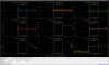
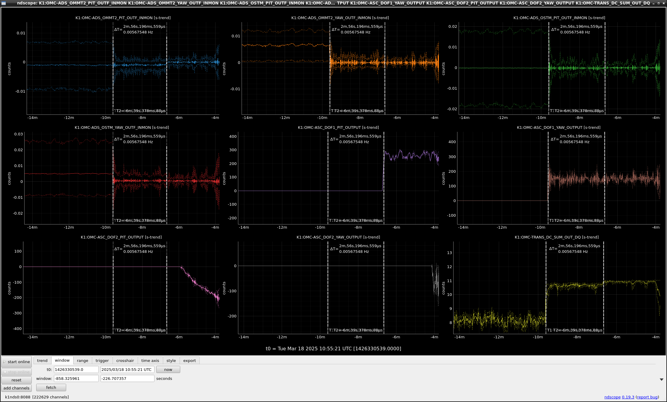
- After that, we closed the loops. Fig. 1 shows the time-series around the moment of engaging the ADS. On closing the DOF1 YAW loop for OMMT2 YAW control at the left cursol, the OMC trans. power improved drastically. After engaging, the OMC trans. power of RF sideband seems to be maximum and the fluctuation got smaller.
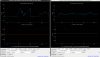
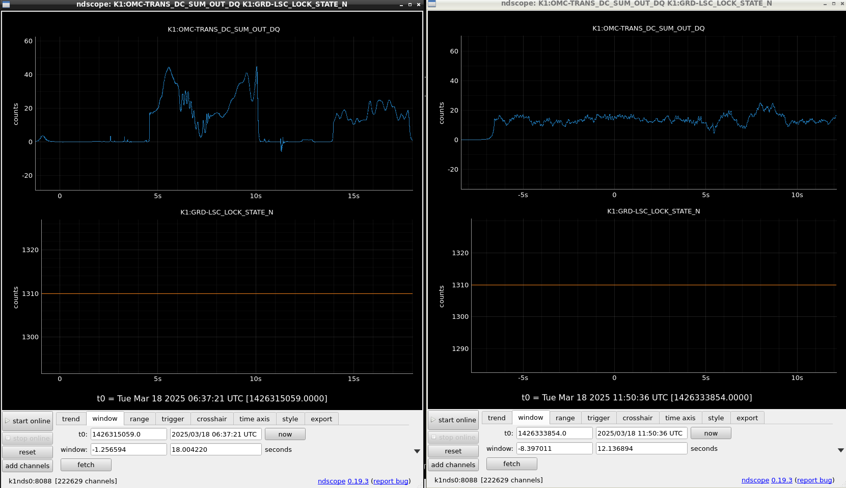
- We restored the threshold values in the OMC_LSC guardian for locking OMC with the TEM00 carrier instead of the TEM00 sideband. And then, we locked OMC with the TEM00 carrier. Fig. 2 show the OMC TRANS power with the TEM00 carrier, left figure shows before the alignment and right figure shows after the alignment. The fluctuatuon of the OMC trans. power of the TEM00 carrier seems to get smaller.
## Note
- The procedure is not implemented yet in any guardians
- The RF sideband maximum power seems to 2 patterns, 10 mW and 11 mW. I'm not sure of the reason why but one of possibillity is that the power of the upper sideband differs from the lower one, and the other is that the ratio of the polarization of the RF sideband depends on the beam position on ITM due to the birefriengence.