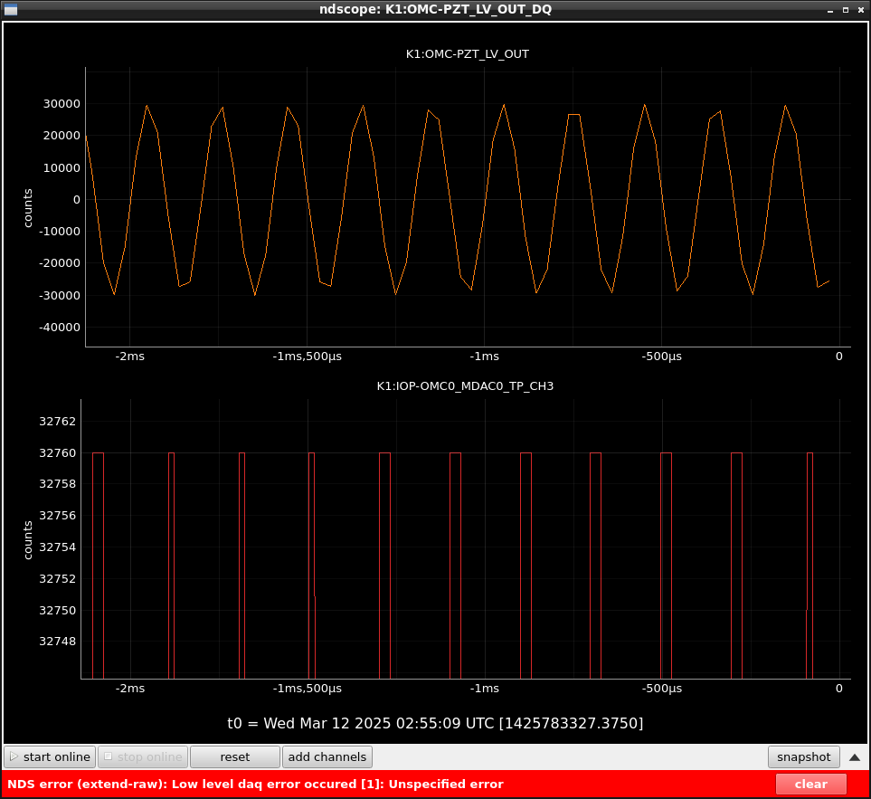
I reduced dither amplitude in DOWN state from 30000ct to 23900ct to avoid DAC saturation.
Because dither amplitude is reduced at the beginning of FIND_RESONANCE_FOR_10W, this change doesn't affect 10W lock. And also, it is reduced in SET_HIGH_IMPEDANCE. So it's also no problem for lock with 400Ohm tans.-impedance. On the other hand, OMC lock with 1.4W and 100Ohm impedance is engaged before reducing dither amplitude. So minor gain adjustment may be required for the low power lock (According to Ushiba-kun's experience, reducing amplitude made lock stable. So this change might be better and no adjustment may be required.)
-----
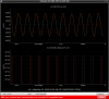
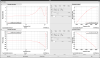
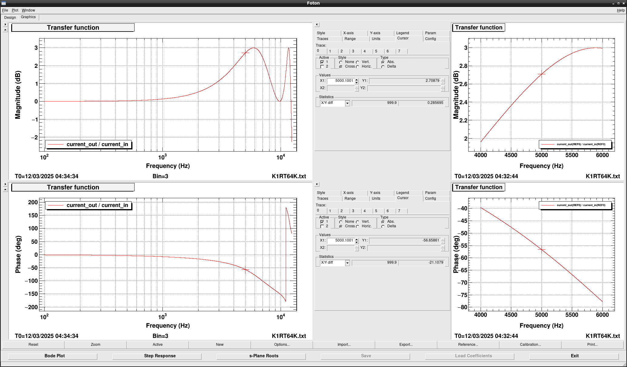
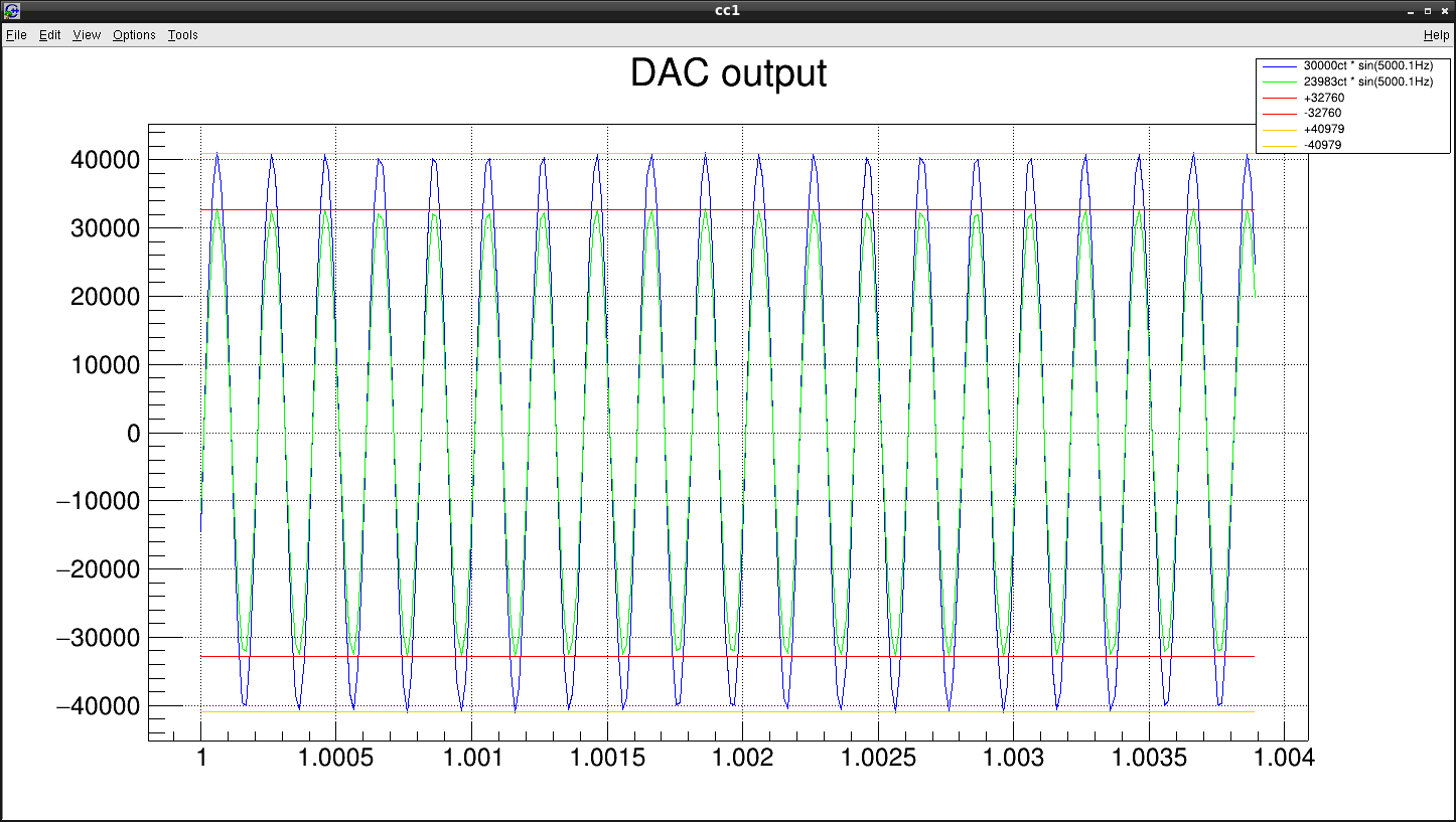
In down state of OMC, a saturation flag was always enabled on models in K1OMC0 and it came from DAC saturation for dither output channel. Dither outputs on 32kHz OMC model and one on 65kHz IOP model are shown in Fig.1 and dither signal on 65kHz reached 32760ct which is saturation limit (note that not 32768ct) though one on 32kHz OMC model is 30000ct. Checking 32kHz => 65kHz digital AI filter, we can find it has ~2.7dB gain around 5kHz which is dither frequency. Figure 2 shows the overview (left panels) and zoom-up view around 5kHz of digital AI response.
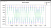
30000ct-5kHz sine wave on 32kHz model becomes 41000ct-5kHz sine wave on 65kHz IOP model. In order to reduce the sine wave amplitude on IOP model less than 32760ct, dither amplitude must be less than 23983ct@5kHz on 32kHzt model. Figure 3 shows the simulation of 32kHz => 65kHz upsampling process for 5kHz dither signal with 30000ct and 23983ct as dither amplitude. A simulation result was as expected, so I changed dither amplitude from 30000ct to 23900ct.