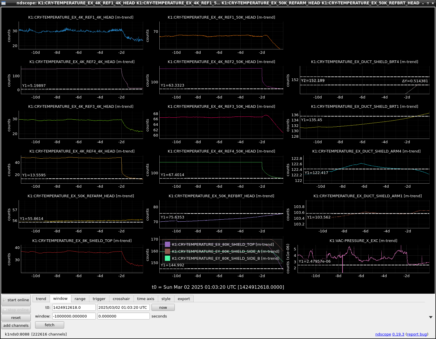
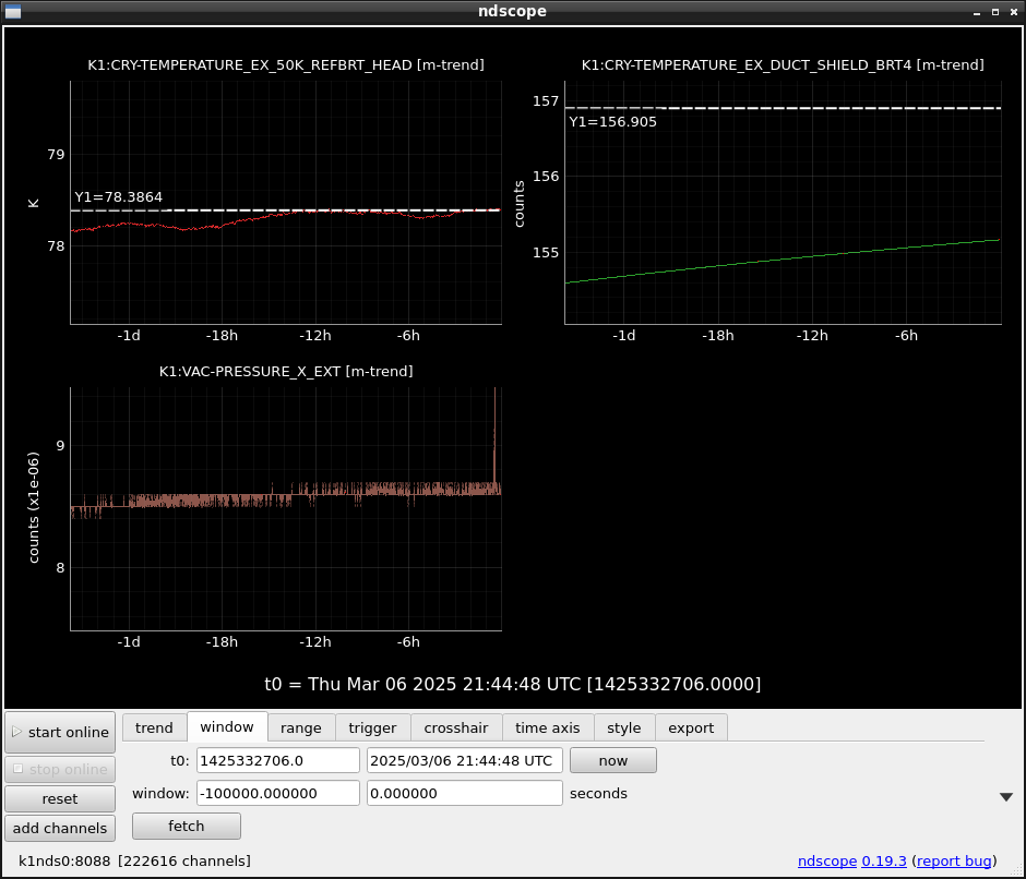
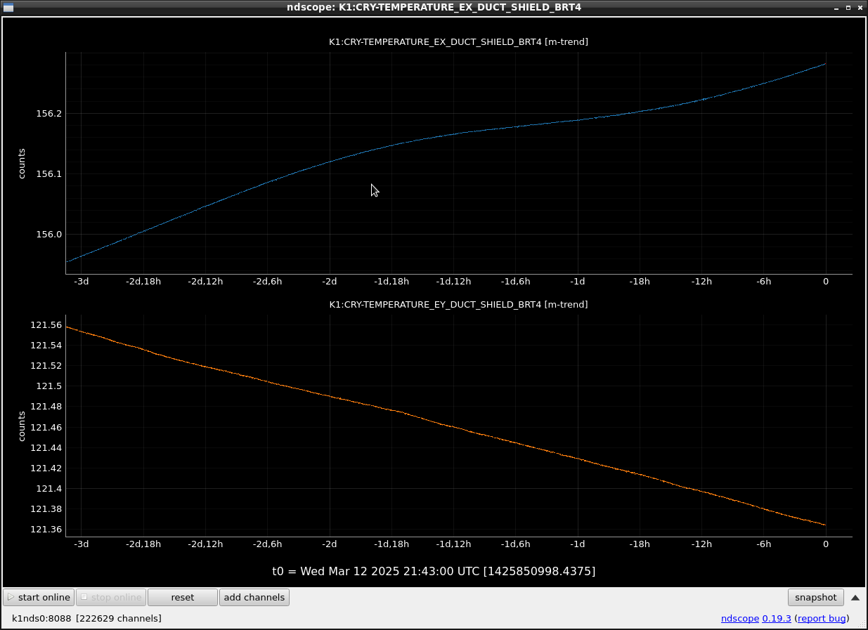
Around 10:20, two EX Payload Cryocoolers started. Ushiba-kun checked the healthy status of the power supplier for the IM heater.
Although we turned on the cryocoolers for the payload, the temp at DUCT SHIELD BRT1/4 kept gradually increasing, according to the increase of the temp at the 50K BRT HEAD. On the other hand DUCT SHIELD ARM4 started slightly decreasing due to the radiation reduction from the 80K shield.
Actually, we have no way to stop the temperature increase of the 50K REFBRT HEAD.
The final trial is to stop the cryocooler for the DUSCT SHIELD BRT until its HEAD temperature reaches 100K, then to restart. This method was tried for the cryocooler for the DUCT SHIELD ARM in "EY", then the cooling performance was recovered and reported as klog#32861.
Because the temp at DUCT SHIELD BRT4 is approaching the critical temp of 157K, we should perform this in the morning of March 3rd in parallel with the OMC vacuum area recovery.
----
Miyoki, Uchiyama, Ushiba, and Kimura discussed the cryocooler's troubles for the DUCT SHIELD ARM in EY and BRT in EX on Saturday and Sunday morning, then we concluded these strategies, considering trying to take any "renewed" sensitivity data using 2 DCPDs and 10W laser power as early as possible.
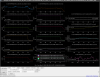
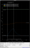
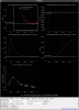
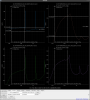
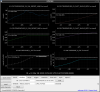
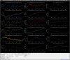
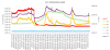
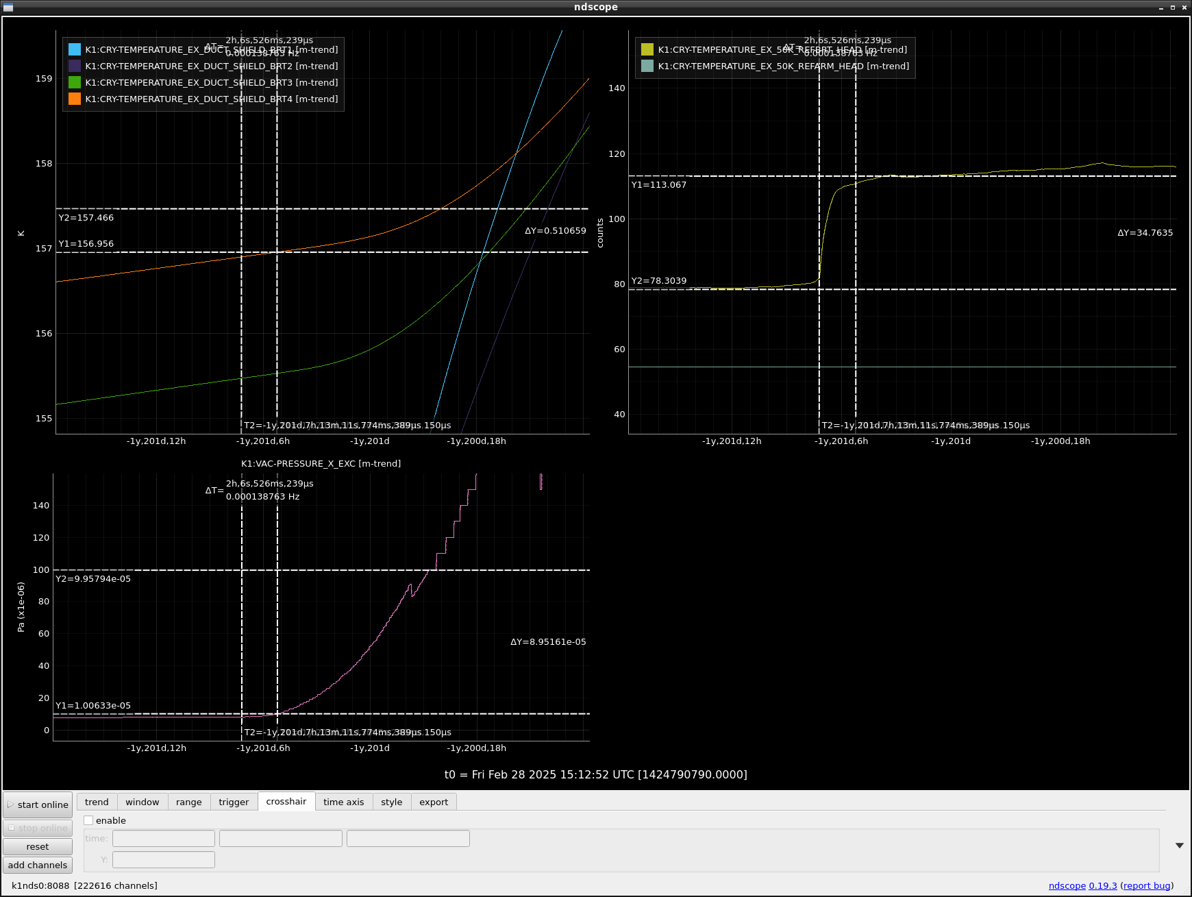
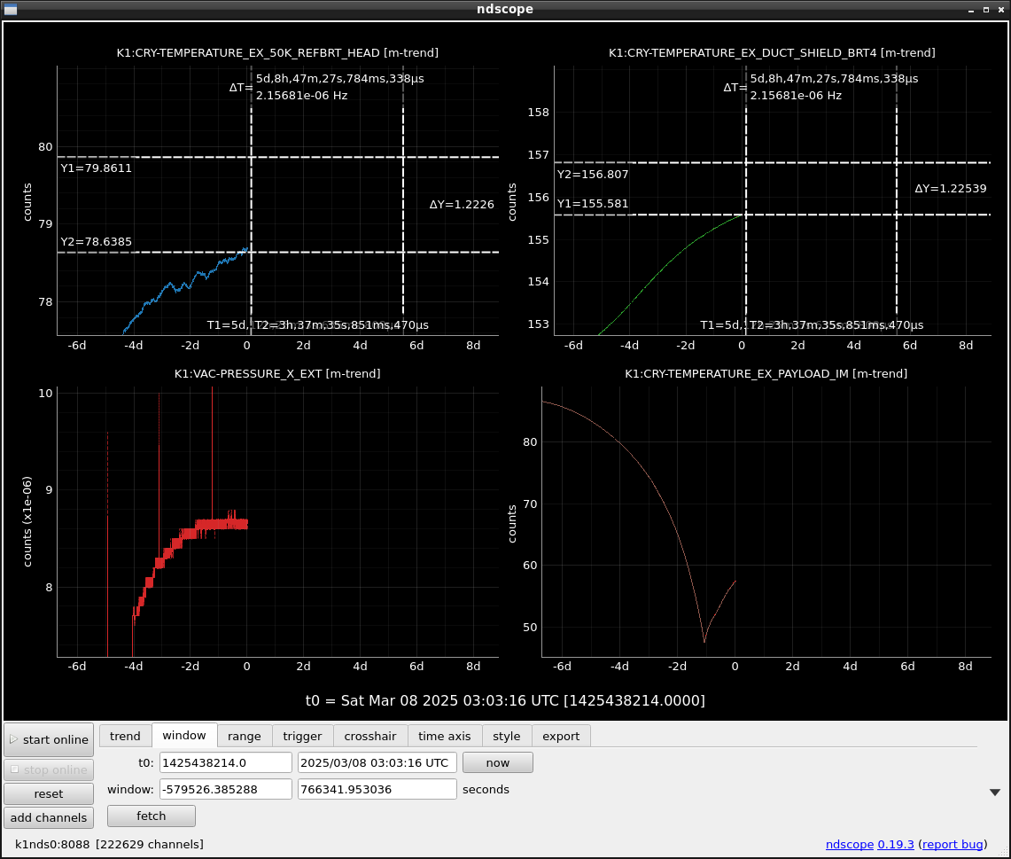
The figure 1 shows the past data when the trouble of the cryocooler for the DUCT SHIELD BRT at EX happened.
In this event, the temperature increase continued at the cryocooler head for the DUCT SHIELD BRT, and a sudden enhancement was observed from 78K to 113K. However, the vacuum pressure enhancement seemed to start ~ 2 hours later when the BRT4 temperature reached ~ 157K.
We guess we are now facing the same event.
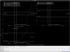
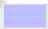
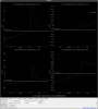
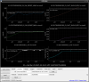
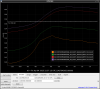
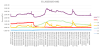
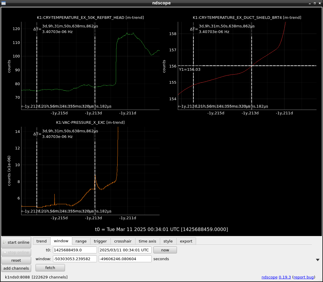
At that time, the cooling performance seemed to be recovered after ~ 1 day as shown in Figure 2. However, slight frosting was detected on the AR surface of the mirror and windows. Also the temp enhancement at the head of the cryocooler could be the trigger for the cooling performance recovery as observed in the cryocooler for the DUCT SHIELD ARM in EY.
The BRT4 side of the duct shield is near the mirror. In addition, the duct shield was inserted "inside" the structure of the outer shield of the cryostat itself. So the outgas from the BRT4 area can easily reach the mirror AR side.
Anyway, the present design of duct shield cooling has no redundancy because there is only one cryocooler for each. We need to consider to add one more cryocooler for each for the reliable commissioning and observation. Otherwise, we will keep losing so much time for the frosting trouble and its recovery.
Or can we recover the frosting on mirrors and windows by only using the IM heaters and window heaters under vacuum conditions?
The temp at EXC1F and maybe 2F increased by 0.3C because of the operation of two more cryocoolers.
Unfortunately, there is no tool for temperature reduction, even if I turned off 1 FFU. I need more reduction of FFU.
The increase rate of the EX BRT Head temp became so slow. The vacuum level at EXT is also very gradually increasing.
ETMX is cooled rapidly (51K: 8K reduction from 59K last morning). So it is better to turn on the heater.
5 days later seems to be the day when water will go out, assuming the BRT HEAD temp increase rate.
So, it is better to take sensitivity with possible achieved improvements.
The comparison between the EY arm and EX BRT which had cooling power reduction troubles.
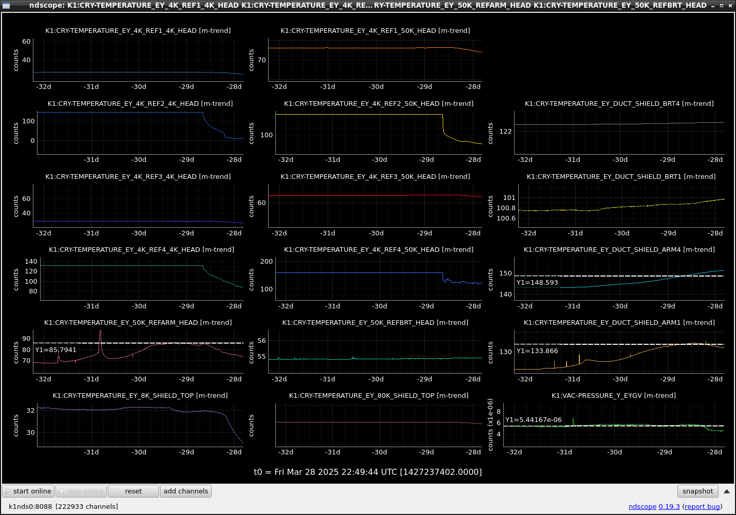
At present, "EX"_50K_REFBRT_HEAD is around 78.4 K. When "EY"_50K_REFARM_HEAD reached this 78.4K, the "EY"_DUCT_SHIELD_ARM4 reached ~145 K. Meanwhile, the "EX"_DUCT_SHIELD_BRT4 reached 155.7K, which is 13 K larger than 145 K.
Although there is a difference in position between the Arm and the BRT sides, the EX BRT side seems to have more heat invasion.
By the way, the temp increase of EX IM is accelerating. This might be because of the thermal conductivity decrease because of the temp increase at the upper stages.
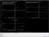
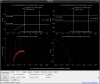
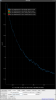
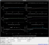
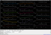
Comparison between similar events yesterday (Fig.1) and over one year and 200 days ago (Fig.2) on the outgas in EXC/EXT and the temp of BRT4 in EX.
When the BRT4 temp reached around 156.0K, the slight outgas was detected in EXT and it is identified to be N2-CO in Fig.1. The same outgas seems to appear in Fig.2 also when the BRT4 temp reached around 156.0K.
So, the outgassing process of H2O after this event is expected as one year and 200 days ago if the BRT4 temp keeps increasing.

The temp of EX_50K_REFBRT_HEAD is increasing again. So, the temp increase of EX_DUCT_SHIELD_BRT4 is expected again.
The increase of the vacuum pressure is because of the increase of H2 and N2-CO, not water.

The worming up speed of EX BRT4 becomes higher.
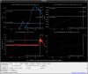
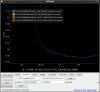
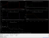
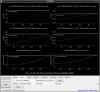
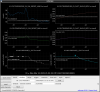
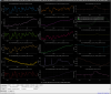
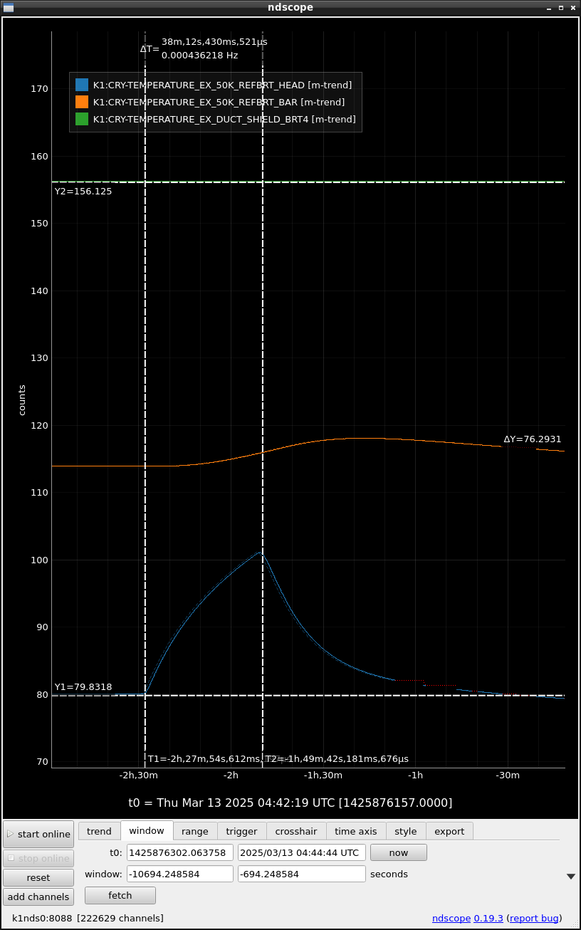
We stopped the cryocooler for the BRT at 11:13 (80K at DUCT SHIELD REFBRT4), waited until the DUCT SHIELD REFBRT4 temp reached 100K, and restarted it at 11:51. So it took "38" minutes for heating up. At 13:12, the temp reached 80K again. So it took "87" minutes to cool to the level of the start. (Fig.1)
In the case of EY, it took one hour and 9 minutes from ~78K to 100K at DUCT SHIELD REFARM4 after stopping the cryocooler for the ARM side. So this fact also shows the more heat invasion is expected in the BRT side than ARM side.
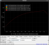
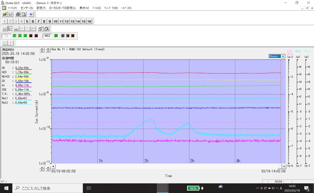
During heating up the cryocooler for the EX BRT, CO2 seems to be released according to the mass spectrometer as Fig.2. The max vacuum level is 1.4*10^-5 Pa due to CO2.
[Just a memo]
The operating pressure of the Xer compressor is below.
Before shutdown;
Supply pressure: 24.0 ~ 24.5 bar
Return pressure: 99 ~ 106 psi
(Charging pressure: 16.5 bar)
After restart;
Supply pressure: 24.0 ~ 24.5 bar
Return pressure: 100 ~ 106 psi
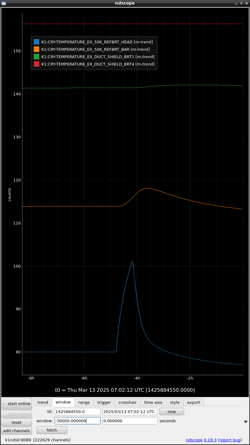
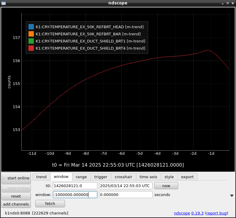
The cooling seems to become steady and stable at present. Even the temp of EX_DUCT_SHIELD_BRT1 started decreasing.

Good black magic.
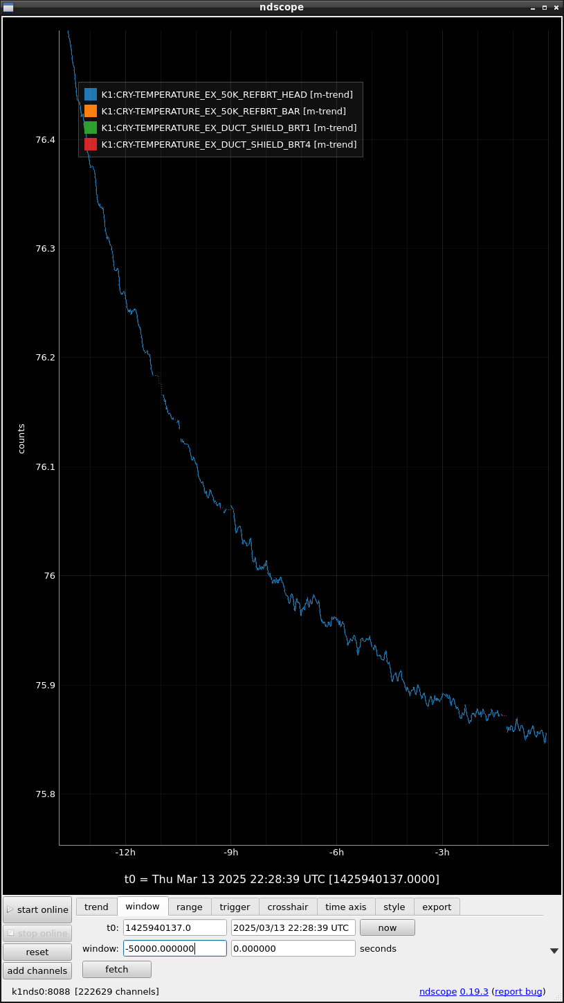
The cooling speed seemed to be stalled. We hope the temp will be kept to be constant around 76K.
The cryocooler HEAD temp starts steadily increasing again. So we need the same stop-and-go again.
According to the information from Sumitomo Heavy Industry, the high-pressure He gas flow at the cryocooler "head" part and the cryocooler head part operation effectively removes impurities.
So, in our stop-and-go case, only the restart timing at the higher temp at the cryocooler head can effectively push out impurities by using the He gas flow. For more effective removal, the several stop-and-go cycles, for example between 100K (or 110K) and 90K, might be able to push out impurities. In other words, the stop timing can degas impurities, and the go timing can push out impurities. The impurities should be absorbed by filters on the flexible tube route and the oil absorber in the compressor.
Steady increase of EX_50K_REFBRT_HEAD, while still a decrease of EX_DUCT_SHIELD_BRT1/4.
The stop and restart retry timing might be between the bottom between temps of BRT1 and 4.
[Kimura and Yasui]
We used surface contact thermometers to measure the surface temperatures of the vacuum chambers in the immediate vicinity of EX's two duct shield cryo-cooler coldheads (Xea and Xer).
From the results of the measurements, we could not identify any areas of low surface temperatures where thermal contact between the vacuum chamber and the cold head was suspected.
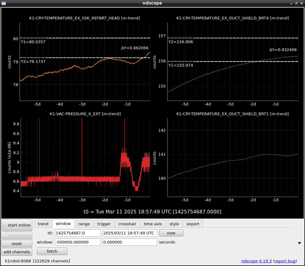
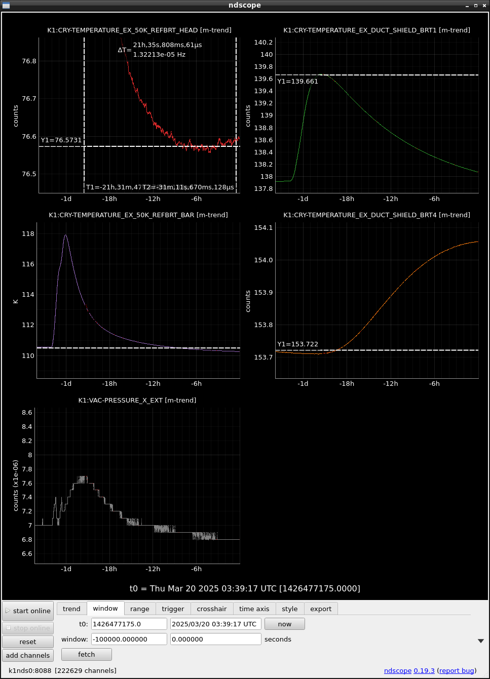
Slight temp increase rate reduction in EX_50KREFBRT_HEAD happened around 3AM today as Fig.1
EX_DUCT_SHIELD_BRT4 is still decreasing.

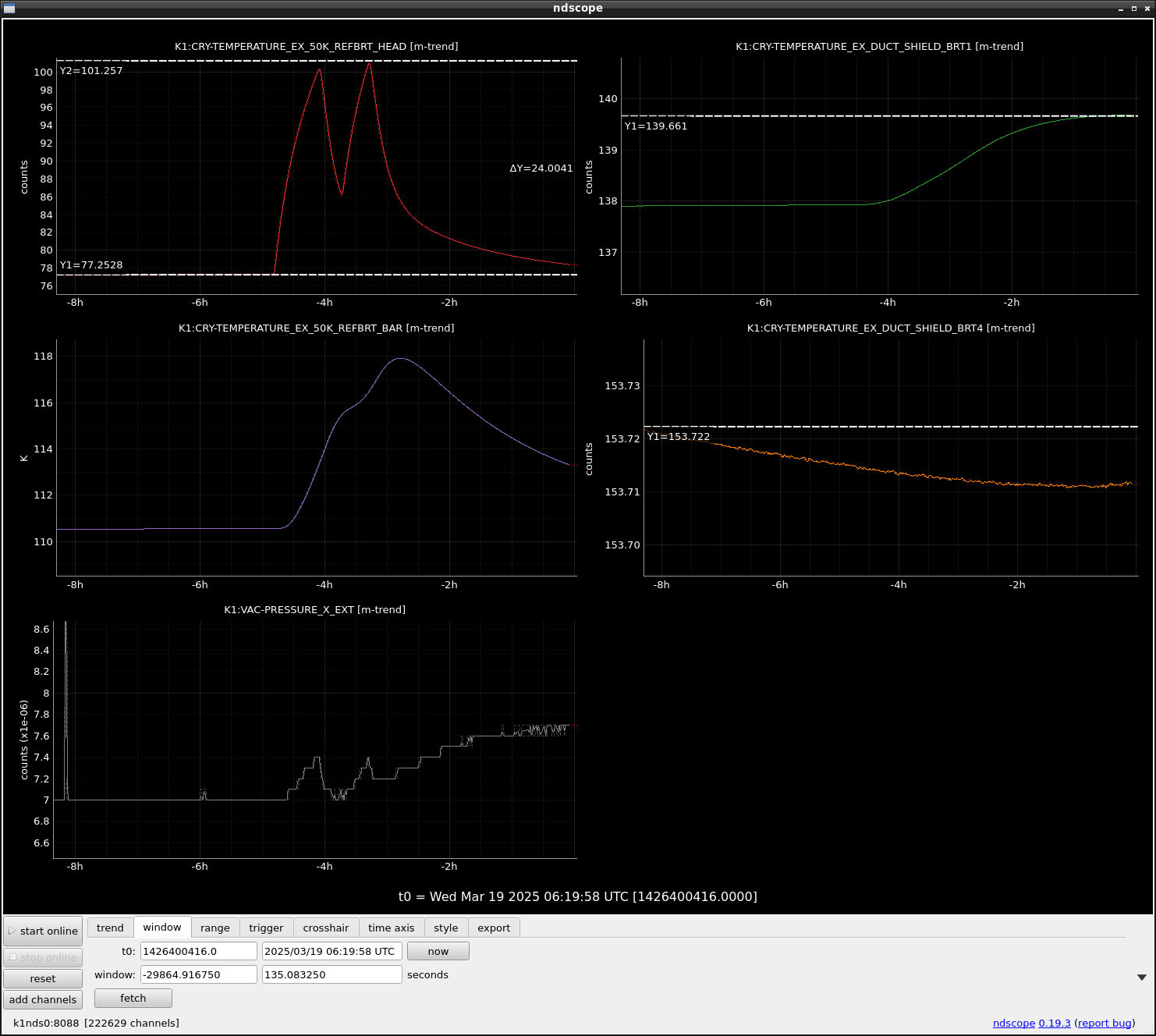
We tried to stop and restart the cryocooler for the EX BRT again because the team of the EX_50K_REFBRT_NEAD started increasing and reached ~ 78K from ~76K.
Two trials were done successively to keep the longer time around 90K~100K for the cryocooler operation.
The first trial showed the same temperature reduction rate at EX_50K_REFBRT_NEAD as the last trial. When EX_50K_REFBRT_NEAD reached around 85K, we stopped the cryocooler again and restarted it at 100K. The second trial's temperature reduction rate became worse by a factor of 1.2. One of the reasons could be the heat invasion from EX_50K_REFBRT_BAR whose temp was higher than the first trial.
During these two trials, the temperature of EX_DUCT_SHIELD_BRT1 approached 141K which was the max temp in the last trial. So I did not perform the third trial to avoid higher temp. On the other hand, the temp of EX_DUCT_SHIELD_BRT4 still kept slight decreasing during these trials.
As with the previous stop and restart, CO2 seemed to be released this time, but the ion current value of CO2 was an order of magnitude smaller than the previous one.
The cooling speed seems to be a half of the last case at present. Maybe the minimum temp will not be below 76K in this time.
So, the successive stop and restart seem to fail to enhance the cooling power. As I explained, the first trial showed almost the same cooling speed as that in the last case. So, a single trial seems to be enough to realize a lower temp at EX_50K_REFBRRT_HEAD.
The next trial may be on the next Monday. The single trial and up to 110K (not 100K as before)?
The head temperature seemed to start increasing from 76.5K which was 75.7K in the last trial.
0.8K difference between the last trial and this time trial.
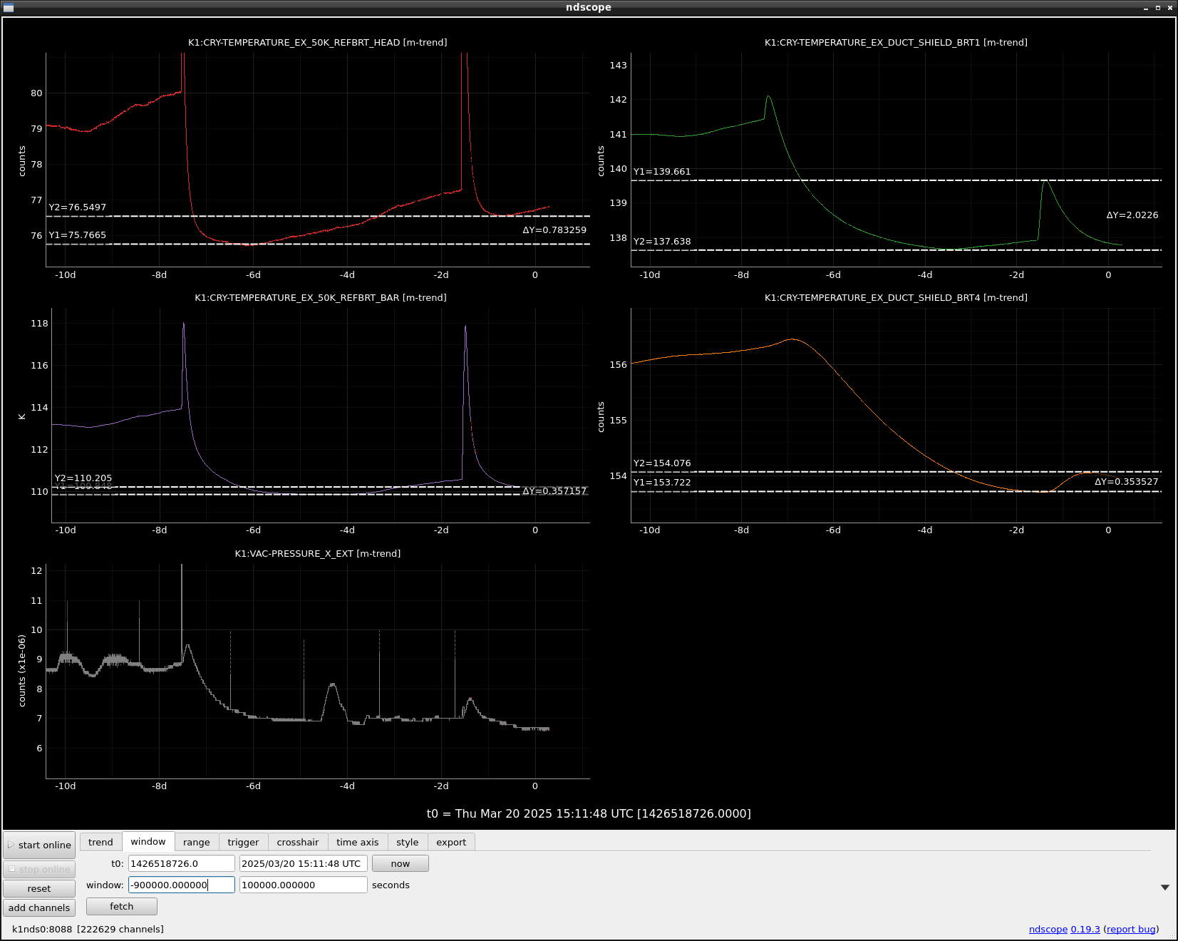
The comparison between the last trial and this time trial.
- The temps of EX_50K_REFBRT_HEAD at stopping time are ~80K and 77.3K.
- The minimum temps of EX_50K_REFBRT_HEAD after restart are 75.8K and 76.5K (diff = 0.77K)
- The minimum temps of EX_50K_REFBRT_BAR after restart are 109.8K and 110.2K (diff = 0.36K)
Memo about cooling speed just after the restart of cooling (calculated by ((Max heat-up temp ~100K) - (start temp at stop))/(recovery time from the max temp to start temp)
- Last case: 21K/80min = 0.25K/min
- this case: 24K/260min = 0.06K/min
Memo about cooling speed just after the restart of cooling (the first 20 minutes just after restart)
- Last case: 14.2K/20min = 0.71K/min
- this case: 1st 13.8K/20min= 0.69K/min, 2nd: 13.1K/20min = 0.655K/min
We tried again to stop and restart the cryocooler for the BRT from 9:50.
Memo about cooling speed just after the restart of cooling (the first 20 minutes just after restart)
- 13 March: 13.7K/20min = 0.685K/min (corrected from the previous value from 0.71K/min)
- 19 March: 1st 13.8K/20min= 0.69K/min, 2nd: 12.6K/20min = 0.63K/min (corrected from the previous value from 0.655K/min)
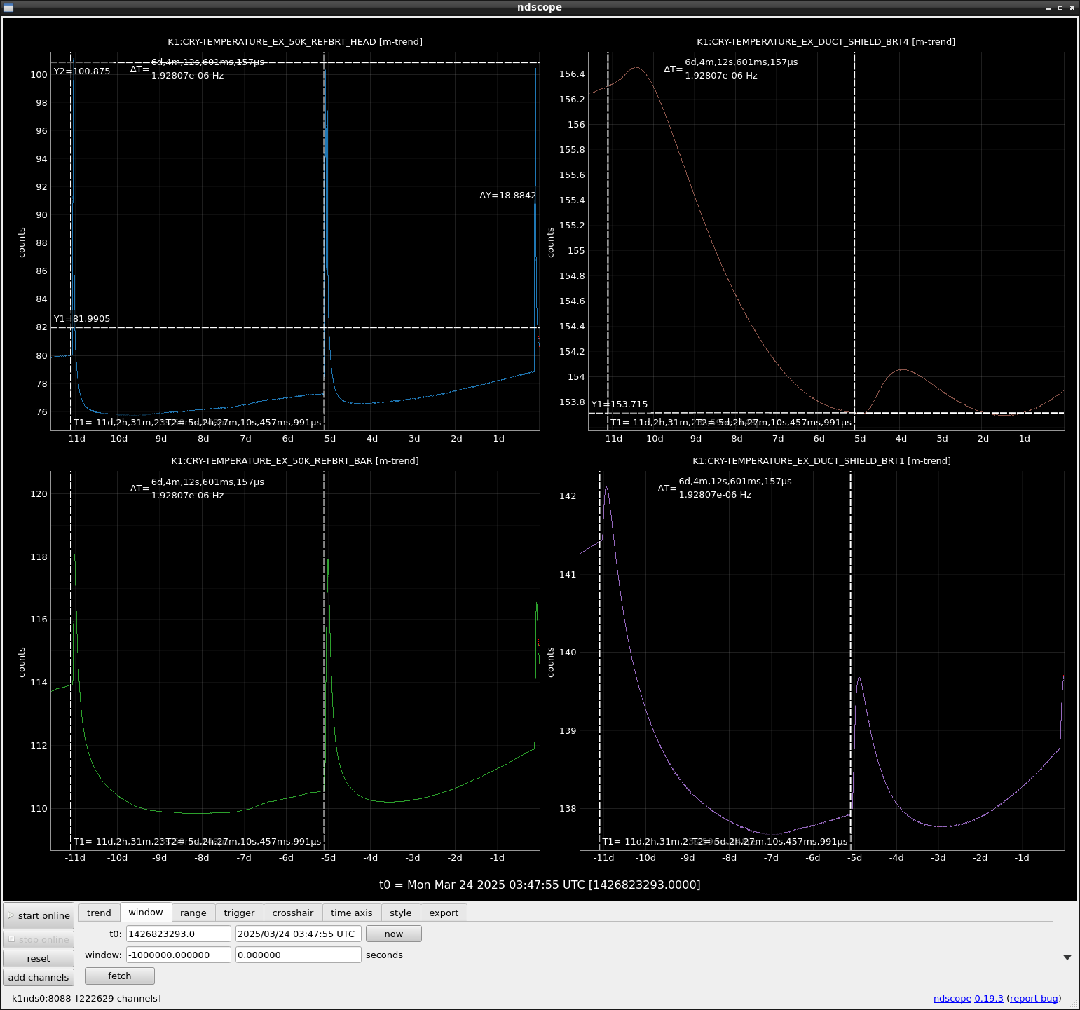
- 24 March: 12.6K/20min = 0.63K/min
So this time is almost the same as the speed on 19 March. We will check the reachable minimum temp.
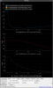
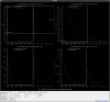
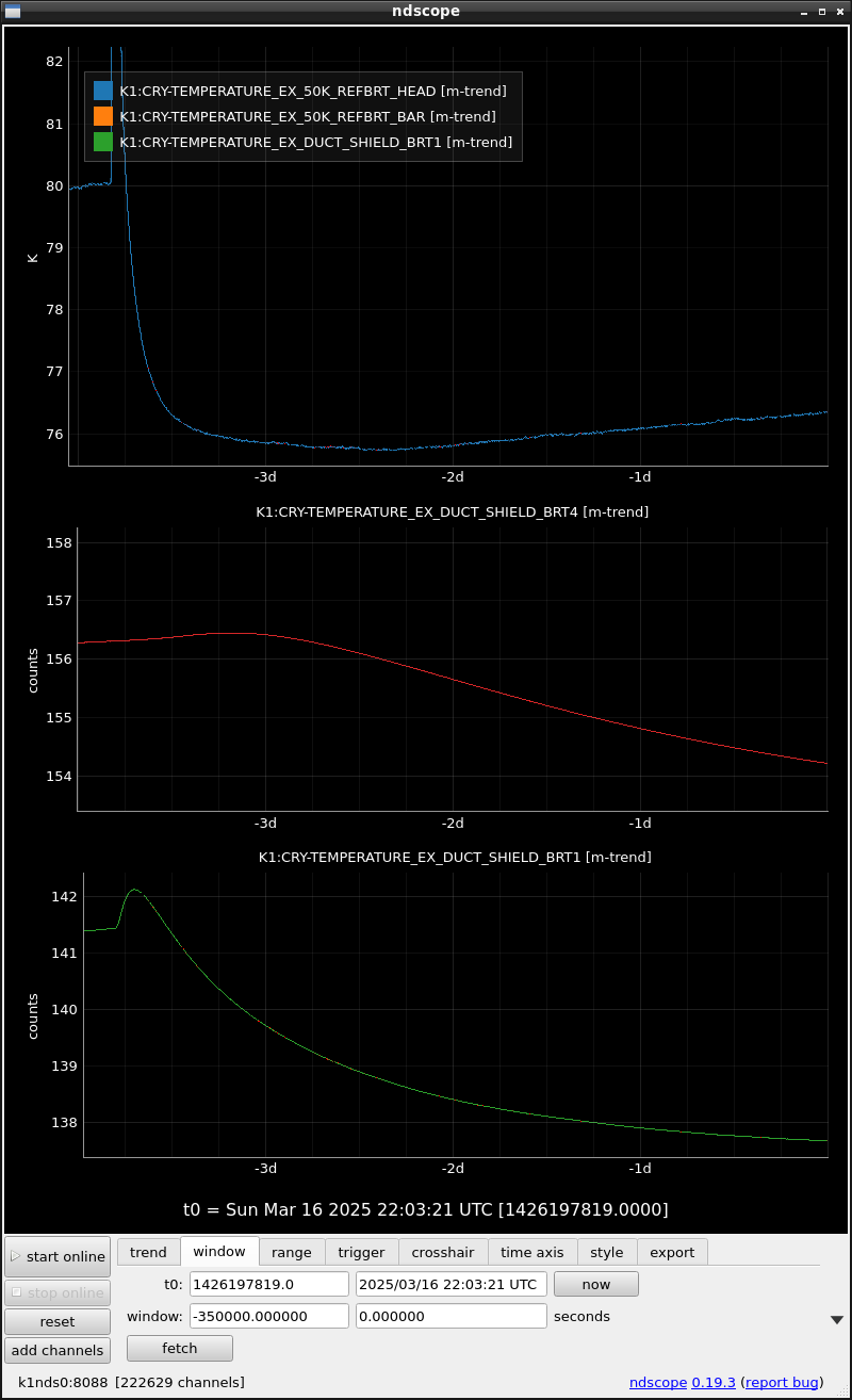
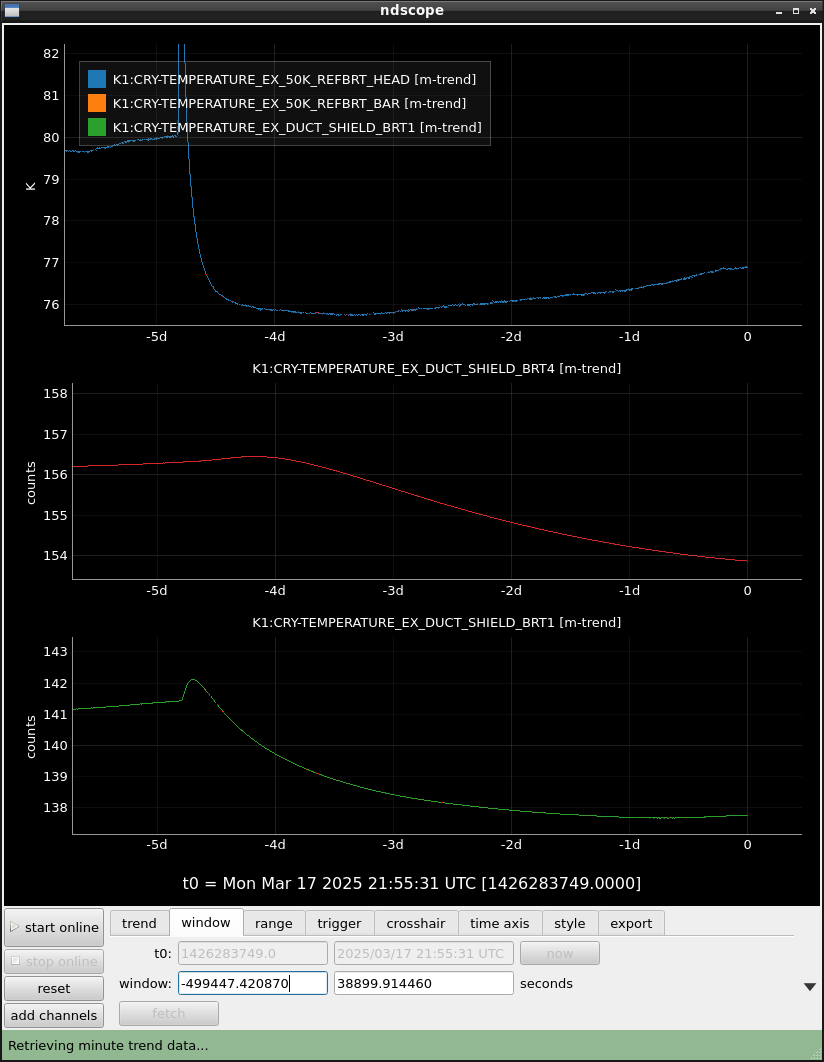
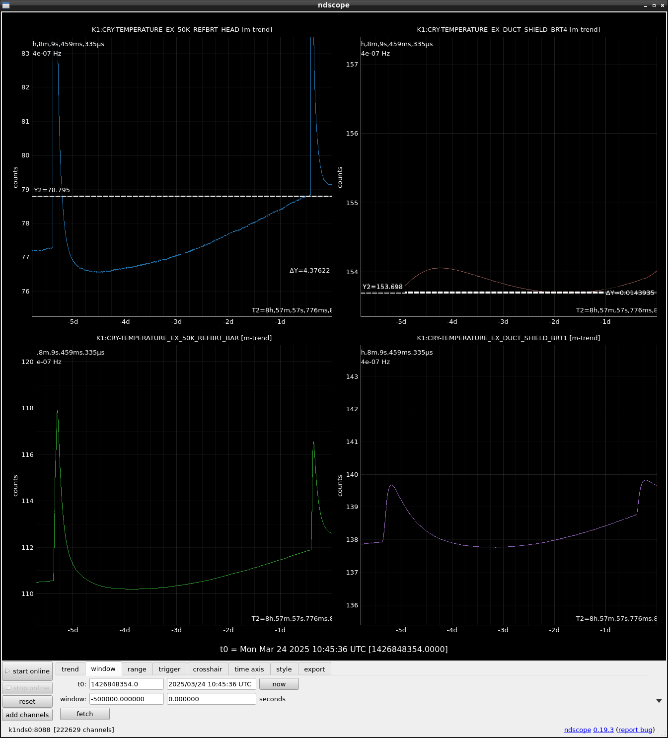
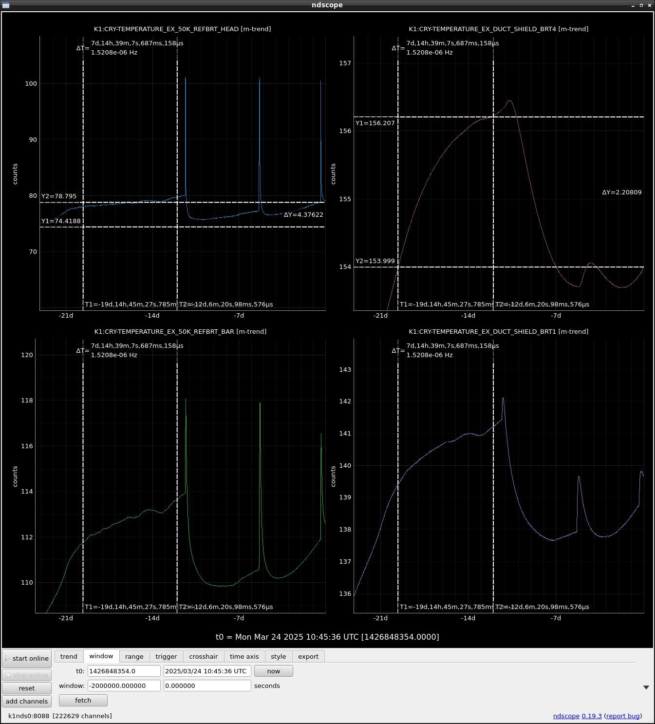
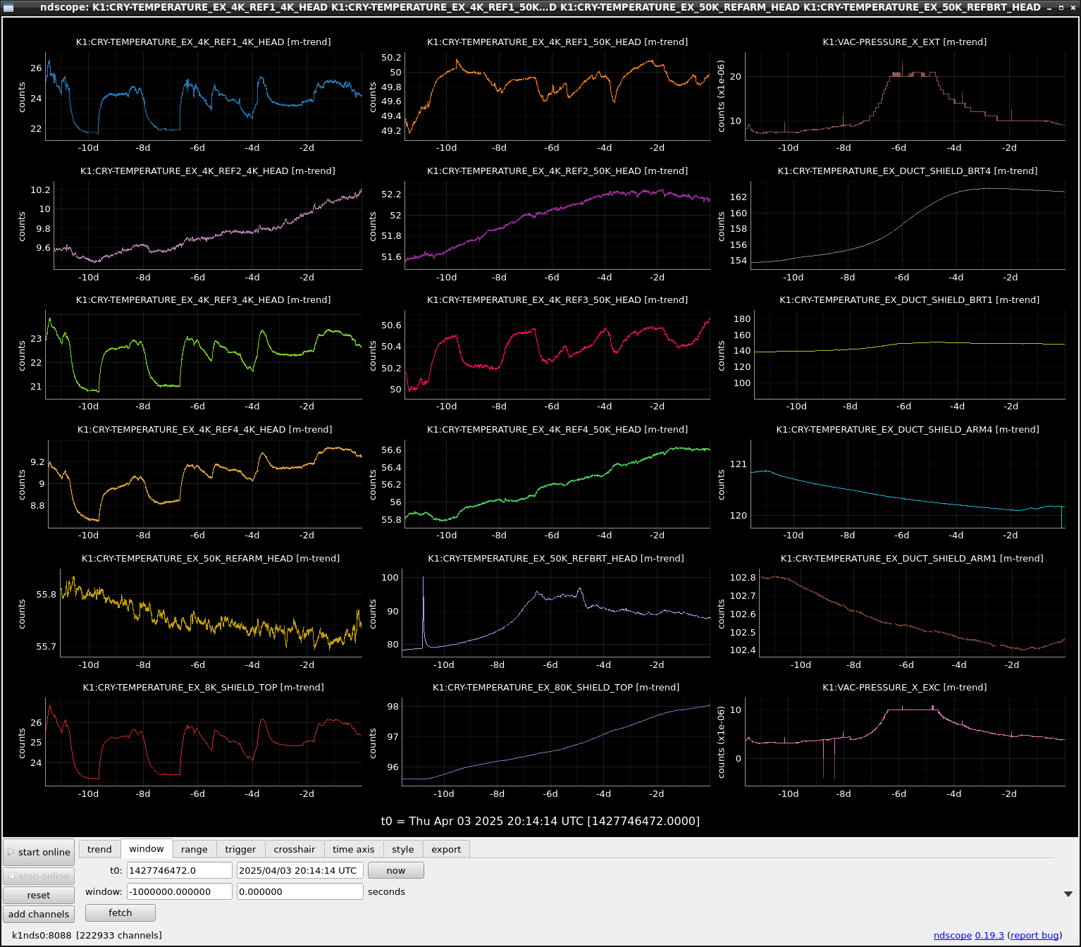
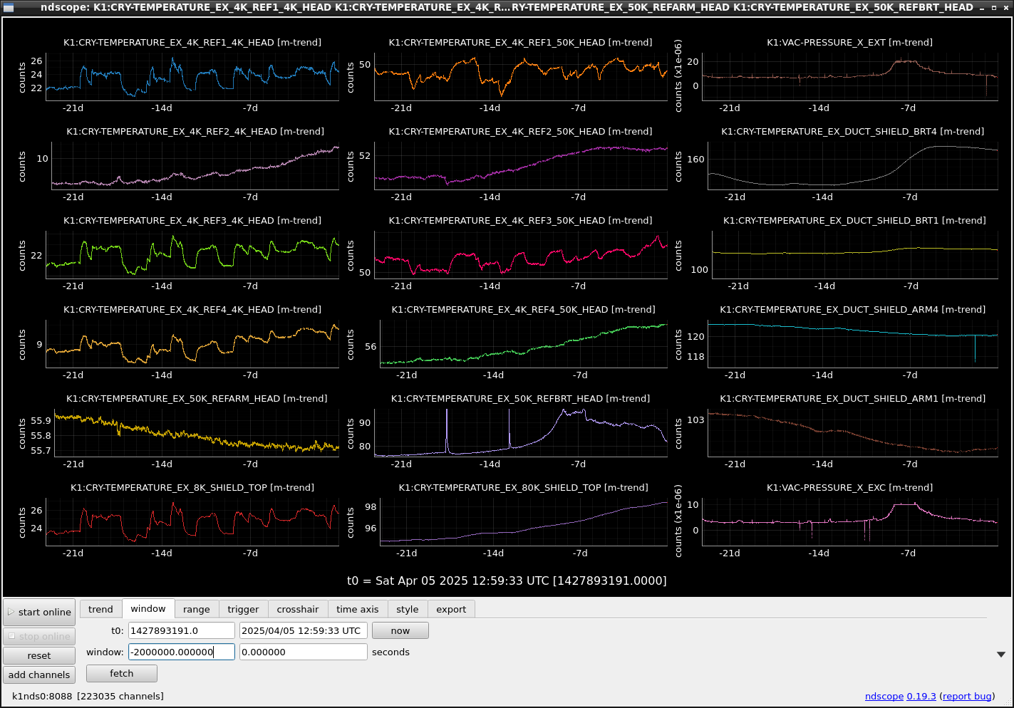
I attached the temp data at REFBRT_HEAD, REFBRT_BAR, DUCT_SHIELD_BRT4 and DUCT_SHIELD_BRT1.
- REFBRT_HEAD temp seems to keep increasing even if we tried stop and restart.
- REFBRT_HEAD temp also seems to keep increasing. In contrast, the peak temps at the trial timing seem to decease.
- DUCT_SHIELD_BRT1 also seems to keep increasing.
- DUCT_SHIELD_BRT4 temp could be smaller only by 0.015K after the second trial (minimum at -1.5 days).
- Stop and restart trials seem to be effective at leat in the recent two weeks. However, its effect will become smaller because the temps at other positions are increasing.
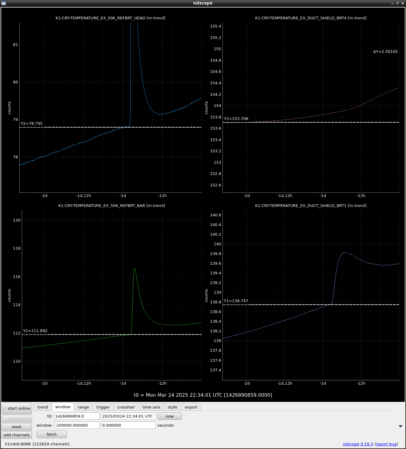
The cooling power was rapidly spoiled and the REFBRT_HEAD temp seems to stop decreasing at a higher level than the starting temp as Fig.1.
One week is expected for the temp of DUCT_SHIELD_BRT4 to reach the last max level of around 156.5K, judging from Fig.2.
The trial on 23 March had completely no improvement as Fig.1 because the increasing trend and speed was clearly kept as before the trial.
Miyoki, Uchiyama
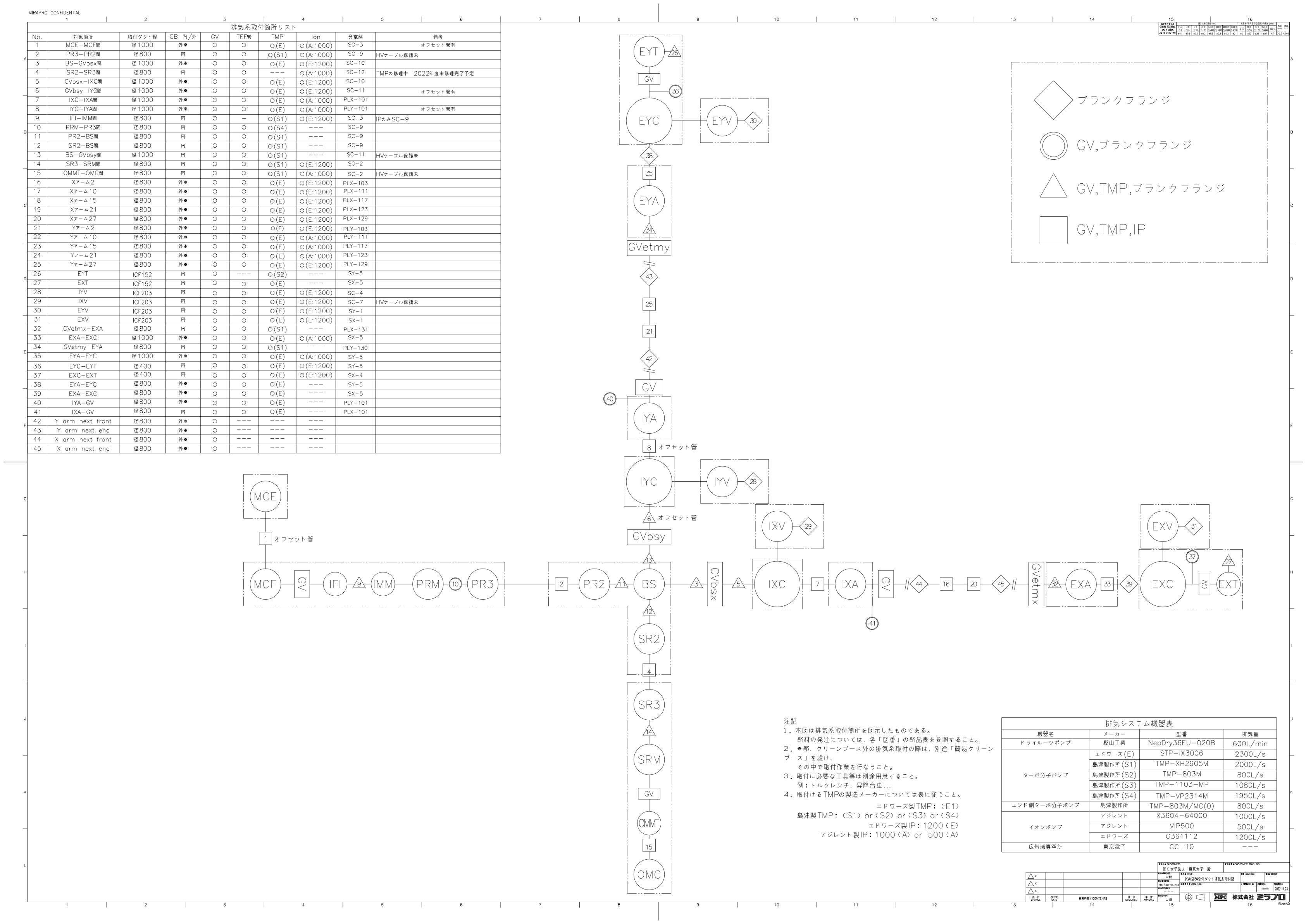
In preparation for the release of H2O due to the increase in the temperature of the duct shield, we stopped 4 ion pumps and started 3 TMPs at around 10:30.
The stopped ion pumps are #33(between EXA and EXC), #39(between EXA and EXC), #37(between EXC and EXT), and #31(at EXV).
The started TMPs are #33(between EXA and EXC), #39(between EXA and EXC), and#37(between EXC and EXT). We did not start the TMP at EXV.

A trend graph of Q-mass in EXC is attached.
The partial pressure of each residual gas in the EXC has decreased due to the switch to turbo molecular pumping.

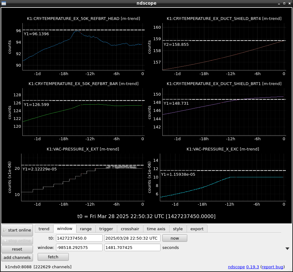
Finally, the BRT4 temp reached the critical temp of 157 K. Then water seemed to start evaporate.

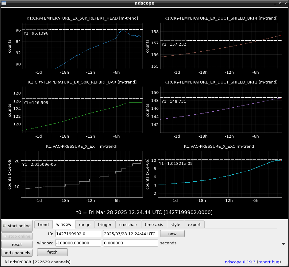
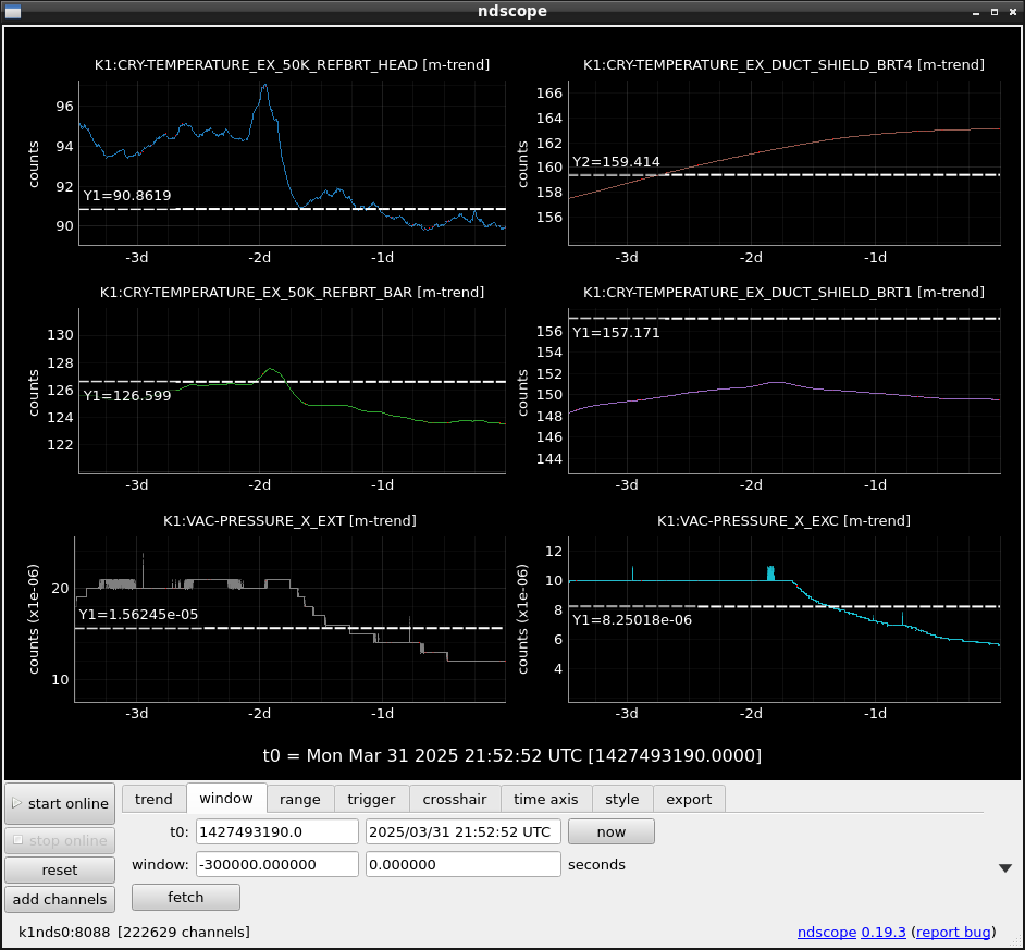
50K REFBRT HEAD temp stopped increasing and is now fluctuating at ~94 K. According to the EY Arm side case, this is a good sign.
The 10 hours later data from the recent report. EX 50K REFBRT HEAD temp is still fluctuating around 93K as Fig.2
In the case of EY 50K REFARM HEAD temp in Fig.1. it also started fluctuating around 86K and one day later, it started cooling.
In addition, the vacuum level (EXT Vacuum level ~ 2*10^-5 Pa) is not as bad as in 2023 (EXC: ~10^-3 Pa at its peak), and it is also fluctuating at this level. Be careful not to have data at EXC because of some trouble.
The EX 50K REFBRT HEAD temps is still around 95K and the vacuum level at EXT is also around 2.1x10^-5 Pa. H2O component is the main, but also is constant around 4x10^-9 Pa, which is about only 2 time larger than before the cooling power reduction.
By the way, the temperature increase is milder this time than the last accident on August 12th (klog#26308). At that time, the temperature and vacuum level enhancement was so quick. Then the TMP operation was done "after" that accident. At this time, they are slow, and TMPs were already operated. Fortunately, the TMPs could keep the balance between outgassing of H2O and pumping down?
I guess the temperature gradient exists from the position of BRT4 to BRT1 (strictly speaking not BRT1 but the connection position between EX 50K REFBRT BAR and the duct shield), crossing the critical temp for the H2O outgassing. This means that the area where H2O will come out becomes a limited ring-like area on the duct shields. This might contribute to the limited amount of H2O outgassing. On the other hand, on August 12th, 2023, the temps at BRT1~4 reached the critical temp successively.

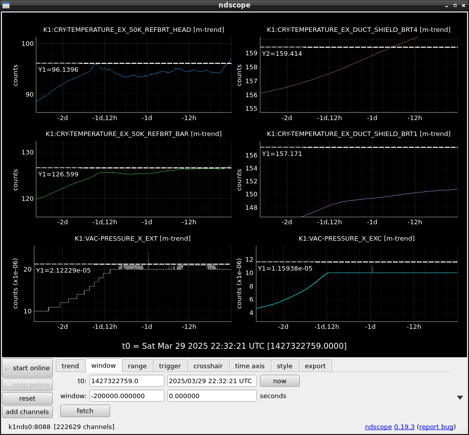
EX DUCT SHIELD BRT1 is decreasing before reaching 157K because the EX 50K REFBRT HEAD temps is kept around 90 K.
Partial water pressure is also decreasing.

EX 50K REFBRT HEAD temp is now gradually decreasing.
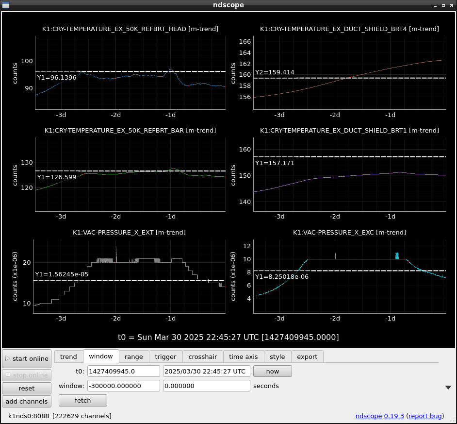
The decreasing trend was kept. Temp at BRT4 also started decreasing. The vacuum pressure at EXT and EXC are also decreasing now.
Abstract
The cryo pumping effect around BRT1/2 is still powerful, and contributes to avoiding the frosting disaster of the mirror?
Considerarion
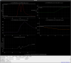
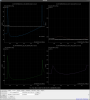
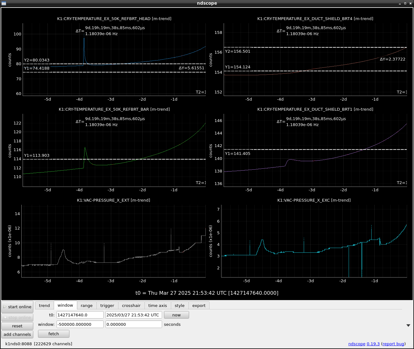
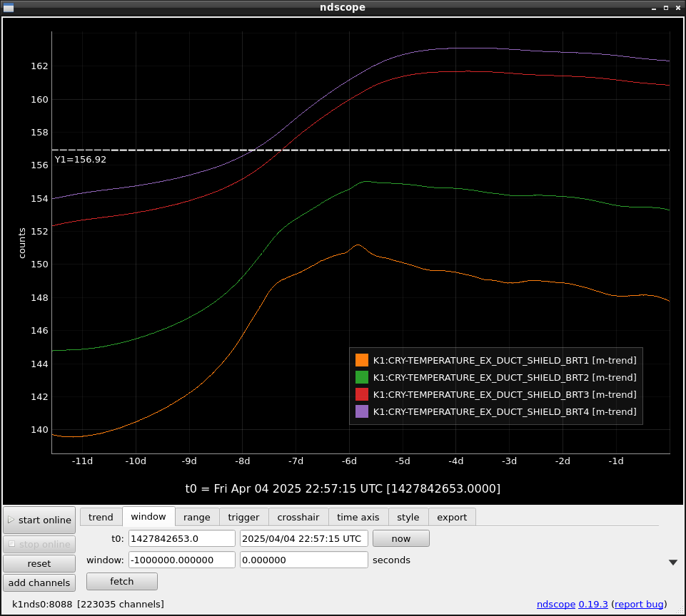
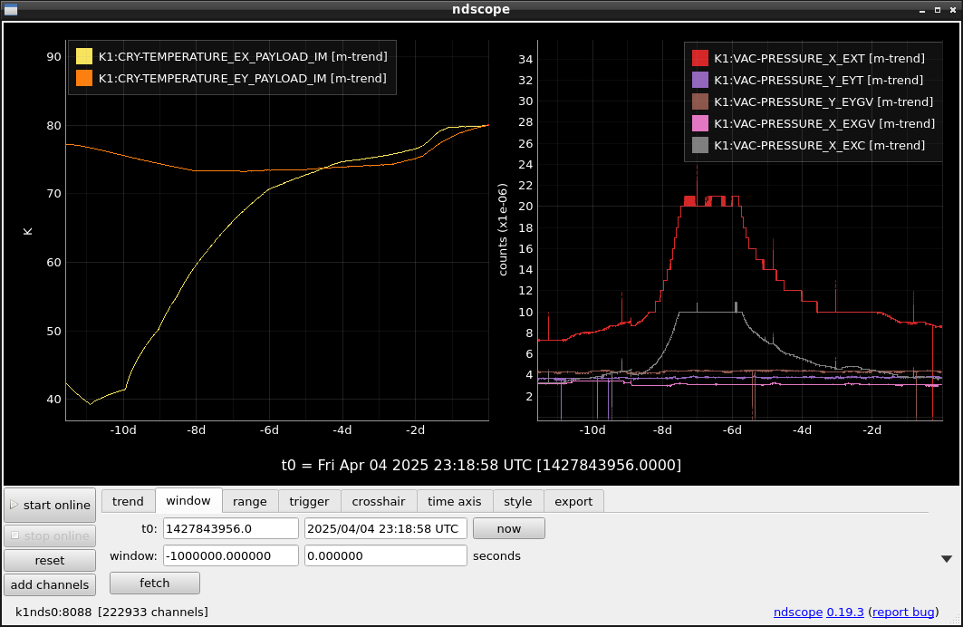
Fig.1 shows the recent temperature changes at BRT1~4 at EX. The temps at BRT3/4 (cryostat side) were over the critical temp of 157K, while temps at BRT1/2 were lower. In Fig.2, the right side shows the vacuum level changes around EXC, EXT, and EXGV.
Fig.1 might explain why the vacuum level at EXT, which is situated between BRT1 and the TMSX window, could be kept lower than that the frosting cases in 2023, August. The limited amount of H2O that would come out from this sandwiched area between BRT2/1 and the 2-layer radiation shield beyond the position at BRT4 seemed to be absorbed by them. In addition, H2O from the TMSX side was also absorbed by the duct shield around BRT1/2. So, the effect of the TMP operation is suspected because the cryopumping effect is much superior to the TMP pumping.
Fig.2 shows the vacuum level at EXT increased by ~ 7 times of the vacuum level at EXGV roughly for two days. This corresponds to the mirror AR side being exposed for 2x7=14 days longer with the vacuum level of the EXGV side.
For the worst case where the temps on all duct shield areas are over the critical temperature, one commercial cryocooler around EXT can stop the continuous H2O injection toward the mirror AR side.

The sudden decrease of the temperature of 50K_REFBRT_HEAD happened. However, it is still around 80K, while 55K for the arm side
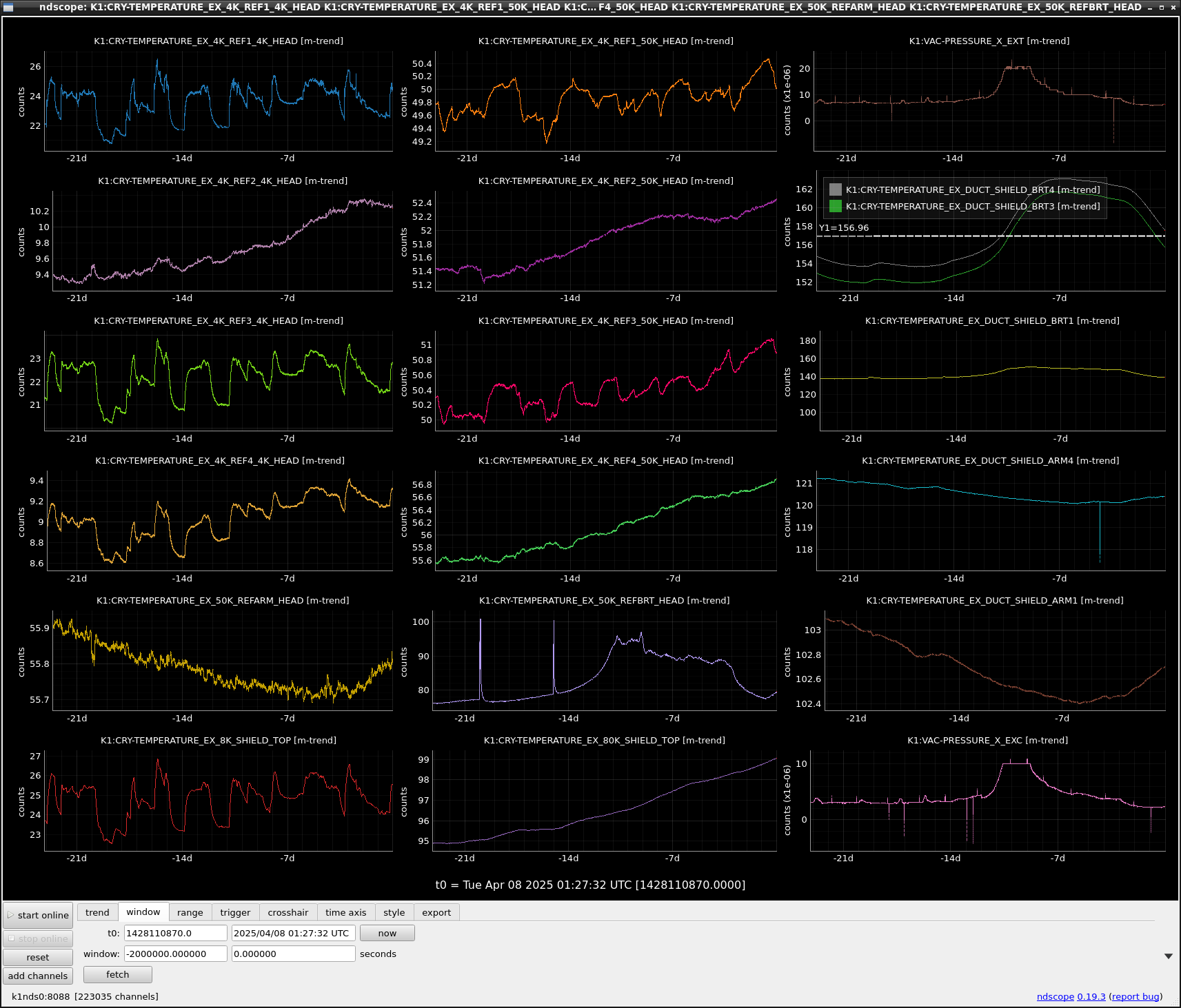
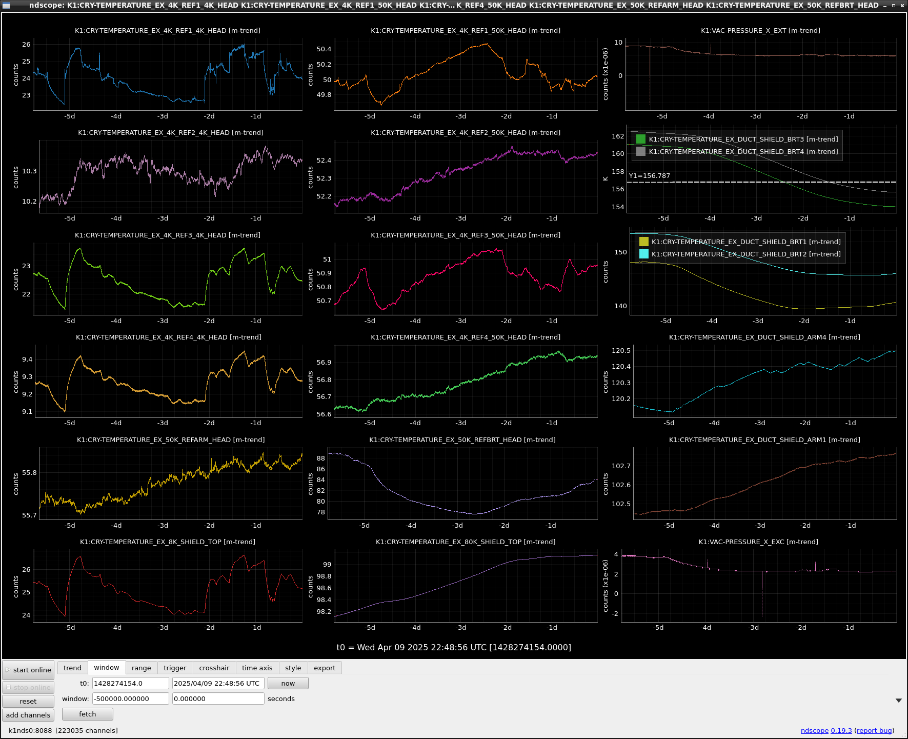
The REF BRT HEAD temperature started increasing again, while the BRT4/3 temperatures kept decreasing. Finally, the BRT3 temperature is now below the critical temperature (157K).
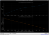
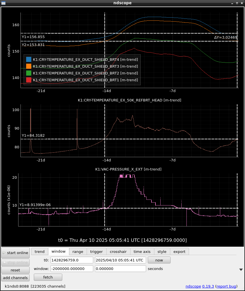
All temps at DUCT SHIELD BRT1~4 are below the critical temp now. While 50K REFBRT HEAD temp is slowly increasing. Please note that the response of BRT1~4 temps is always delayed by 0.5 ~2 days from the change at 50K REFBRT HEAD according to their positions.

Fig1 shows temps at BRT1-4, temp of the REFBRT HEAD, and EXT vacuum level.
The present and around -14 day show the same level for each data, except for the temp of EXT pressure. This is strange. It is natural to expect the higher temp at the REFBRT HEAD results in the higher pressure level at EXT. However, the present EXT vacuum pressure is still low. Why? I just should wait for several days?

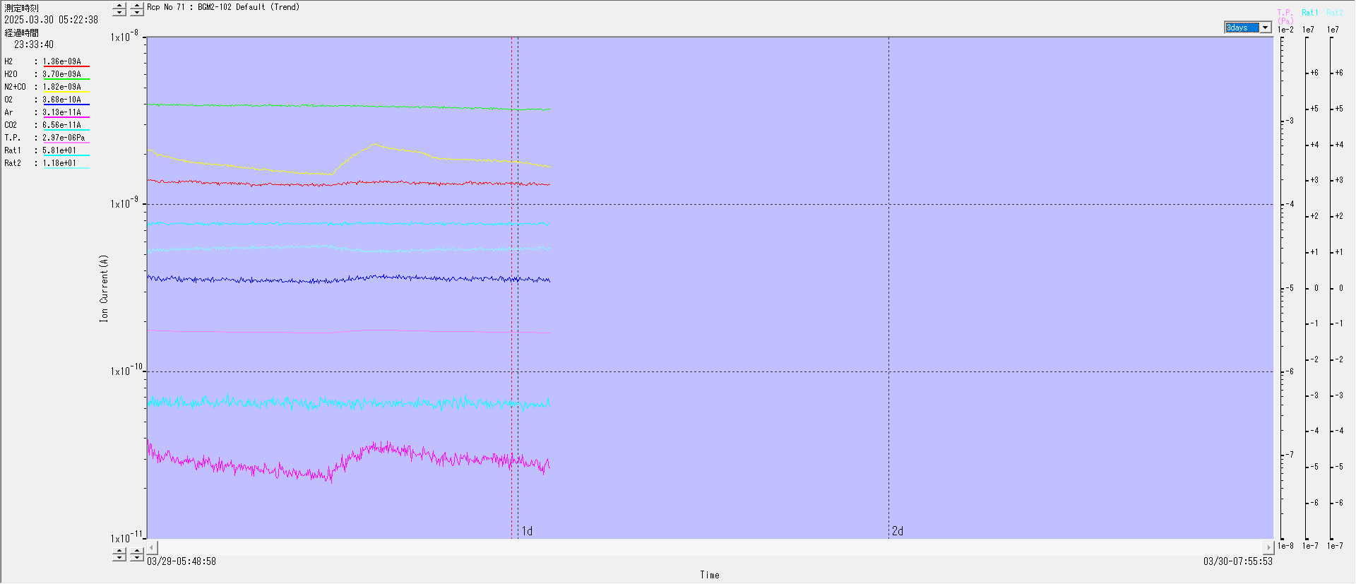
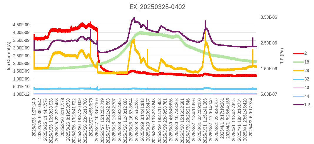
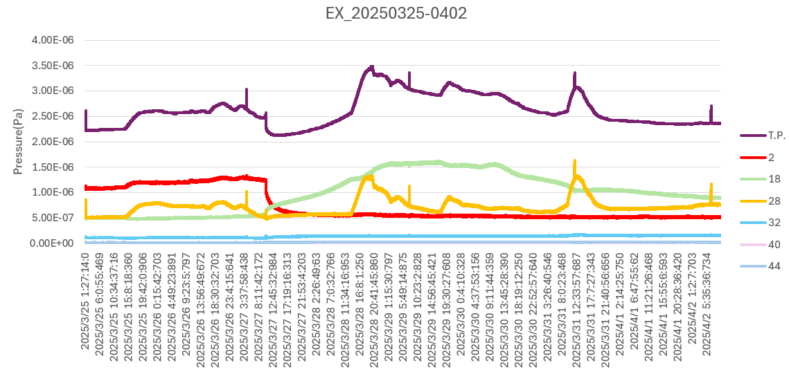
Kimura, Yasui
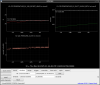
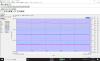
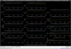
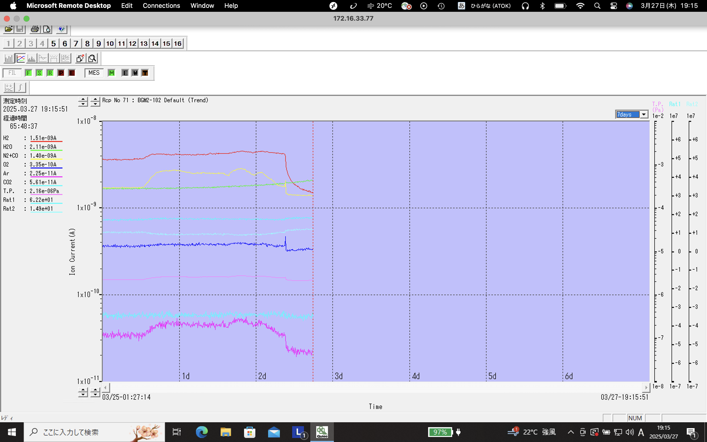
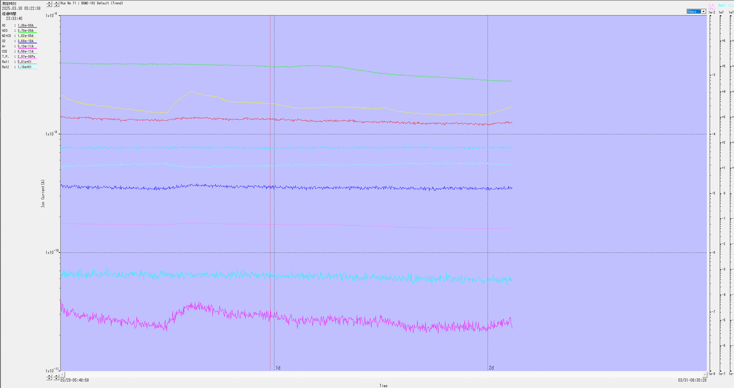
They made a Q-mass plot at EX from 2025/03/25, 1:27 to 2025/04/02, 5:00.
Figure 1 shows the ion current of each component.
Figure 2 shows the partial pressure of each component.
The plot indicates an abundance of H2O and N2 gas.
At 17:00 on 2025/03/29, H2O reached its peak pressure of 1.62E-6Pa.