Abstract
We conducted the IFO calibration with pcal.
The estimated parameters are as follows.
1. Actuator efficiency of ETMX
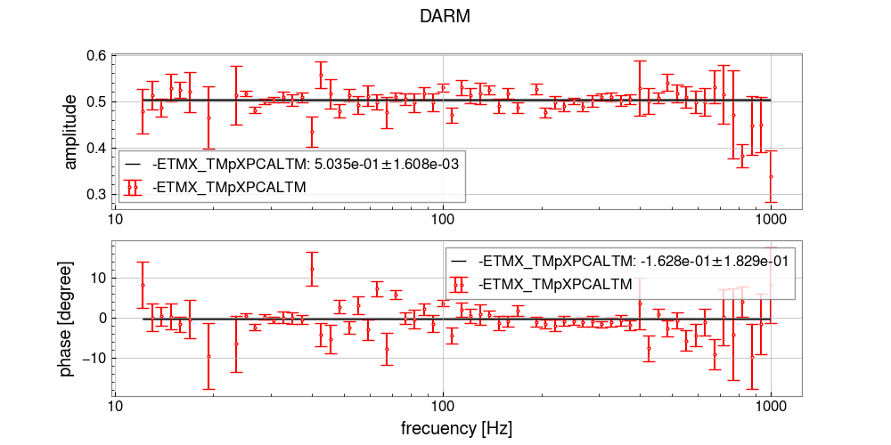
H_etmxtm = -3.7791e-14 +/- 0.0121e-14 [m/ct] at 10 Hz
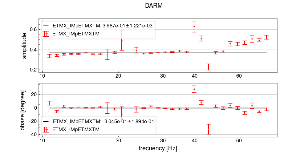
H_etmxim = -1.3932e-14 +/- 0.0064e-14 [m/ct] at 10 Hz
2. Optical Gain
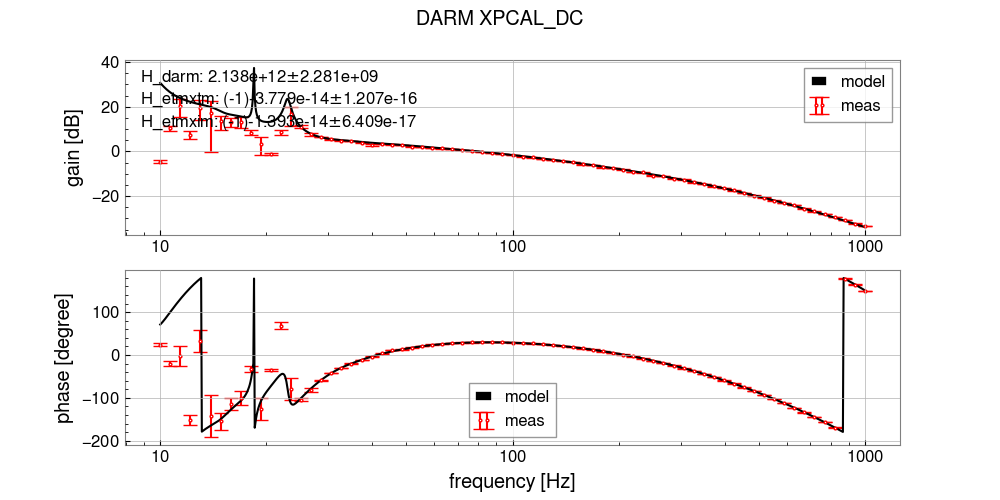
Optical gain = 2.1383e+12 +/- 0.0023+12 [ct/m]
Please note that since the reconstruction filter with the updated parameters has not been loaded yet, the currently generated h(t) does not reflect the results of this calibration.
Details
The actuator efficiencies were estimated using the same method described in klog#30107 (with Pcal as the reference), and then the optical gain was determined from the fitting between the OLTF model and measurements.
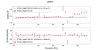
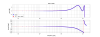
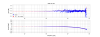
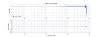
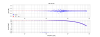
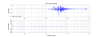
Fig. 1 shows OLTF model + fitting results. Fig. {2, 3} show ratio ETMXTM/PCAL and ETMXIM / ETMXTM.
Additionally, to observe the effects at high frequencies, the endpoint was changed from 500 Hz to 1000 Hz.
The measurement intervals were set at equal spacing on a logscale, and no adjustments were made to avoid existing peaks.
Measured transfer functions are stored in "/users/CAL/current/measurements/2025/0219/".
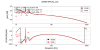

Though there is no impact to estimate the actuator efficiency and optical gain, there is unknown delay as ~15us in OLTF model. Because there is no mismatch between the model and the measurement of OLTF gain, it should come from time delay or poles (or negative zeros) above 1kHz which is upper boundary of the frequency region in today's measurement. I couldn't find such high frequency poles in the digital filters on DARM loop. In addition, I measured time delay between ADC to DAC and couldn't find a cause of ~15us. As the next step to find a cause of unknown delay, we also need to measure the time and phase delay in the analog part.
-----
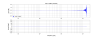
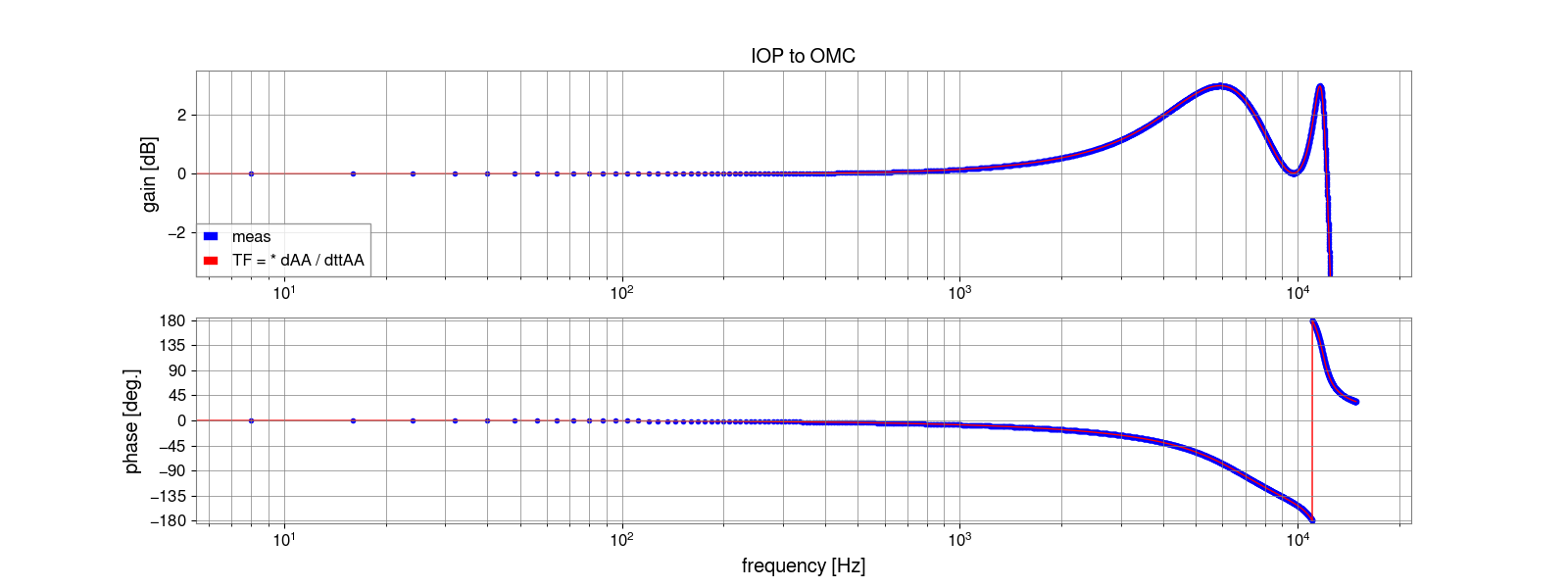
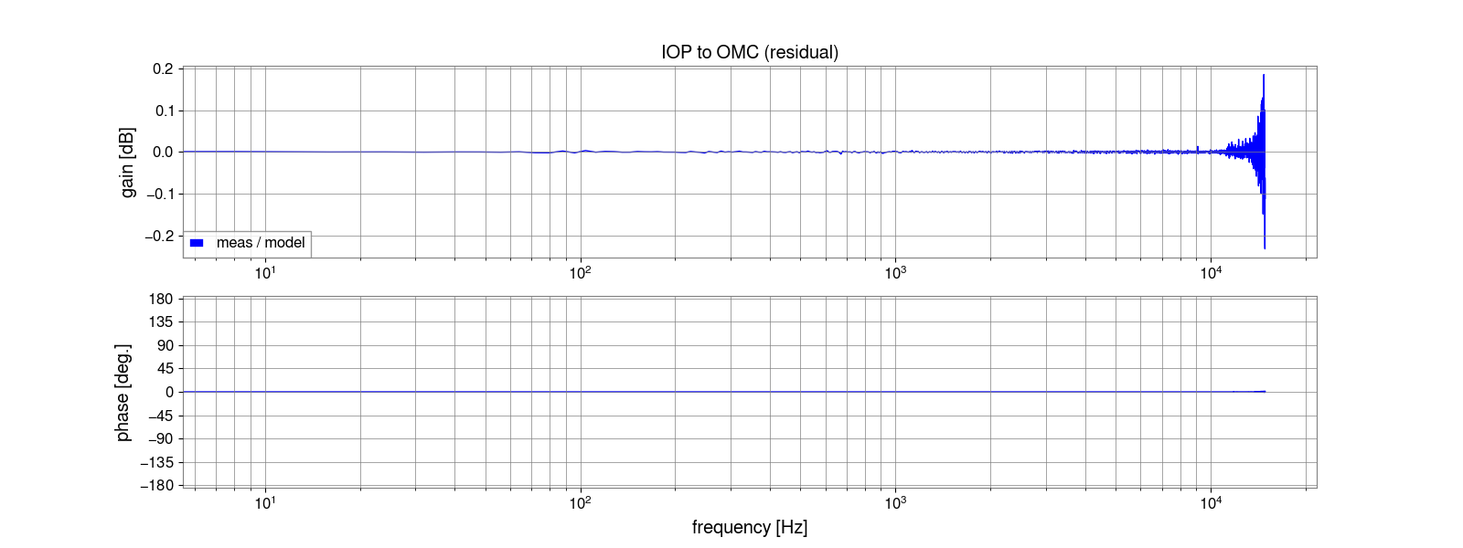
Time delay between IOP model and OMC model
It was evaluated by measuring TF from K1:IOP-OMC0_MADC0_TP_CH0 (65kHz) to K1:OMC-TRANS_DC_A_IN1 (32kHz). Theoretically, there is no time delay between these models. But this transfer function contains the digital AA filter to do downsampling from 65kHz to 32kHz. In addition, diaggui also applies anti-aliasing filters for the downsampling of K1:IOP-OMC0_MADC0_TP_CH0 from 65kHz to 32kHz in order to unify the sampling rate on its measurement. So the measured TF contains AA filter by RCG and AA filter by diaggui. Measured TF is well matched with theoretical model as shown in Fig.1-2.
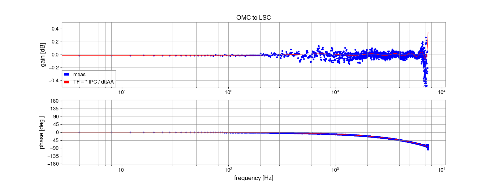
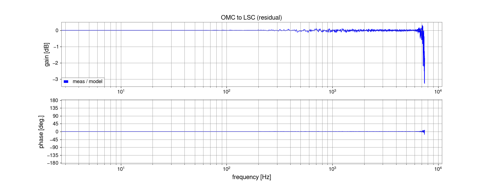
Time delay between OMC model and LSC model
It was evaluated by measuring TF from K1:OMC-TRANS_DC_AA_OUT (32kHz) to K1:LSC-OMC_DC_IN1 (16kHz). OMC model and LSC model communicate each other via Dolphin IPC. Dolphin IPC has 1-sample delay in 32kHz (~31us). Because the sampling rate of these two channels are different, diaggui applies anti-aliasing filter for the downsample of K1:OMC-TRANS_DC_AA_OUT from 32kHz to 16kHz in order to unify the sampling rate on its measurement. There is also no mismatch on this part as shown in Fig.3-4.
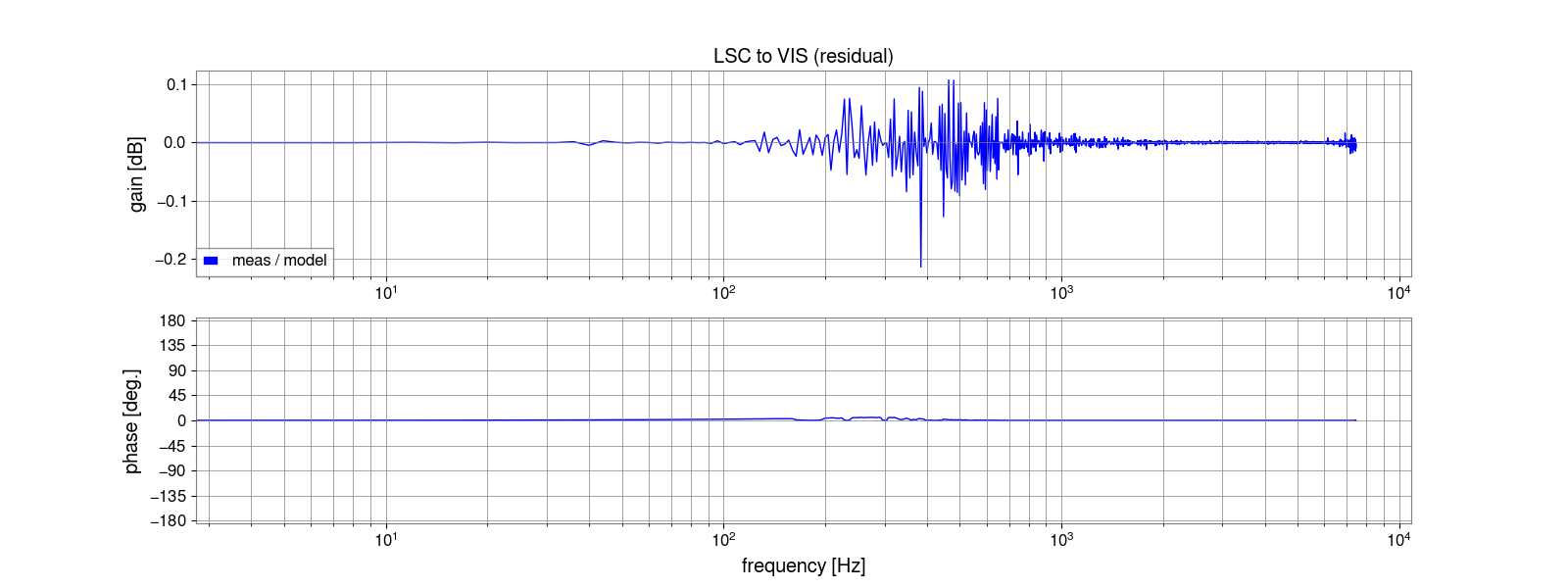
Time delay between LSC model and VIS model
It was evaluateed by measuring TF from K1:LSC-DAMR2_OUT (16kHz) to K1:VIS-ETMX_TM_ISCINF_L_IN1 (16kHz). LSC model and ETMX model communicate each other via RFM IPC. RFM IPC has 1-sample delay in 16kHz (~61us). These two channels are same sampling frequency. So there is no additional filters by diaggui. Note that sign is flipped by LSC_OUTPUT_MTRX and phase in low frequency is 180deg instead of 0deg. Measured and model TFs are shown in Fig.5-6. It's also no problem.
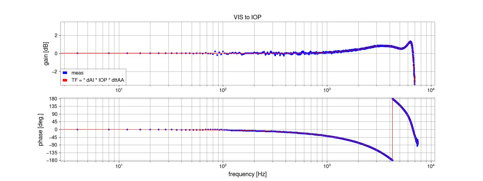
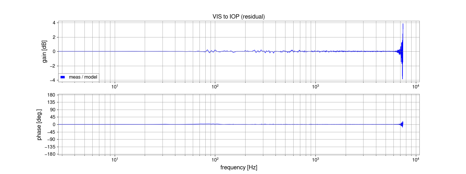
Time delay between VIS model and IOP model
It was evaluated by measuring TF from K1:VIS-ETMX_TM_COILOUTF_H1 (16kHz) to K1:IOP-EX1_MDAC1_TP_CH12 (65kHz). On the signal path from the user model to the IOP model, there are 1-sample delay in 16kHz (user model rate) and digital AI filters. In addition, diaggui aaplies anti-aliasing filters to unify the sampling rate of these two channels on its measurement. On this part, there is no difference between the model and measured TFs as shown in Fig.6-7.
Time delay on ADC and DAC
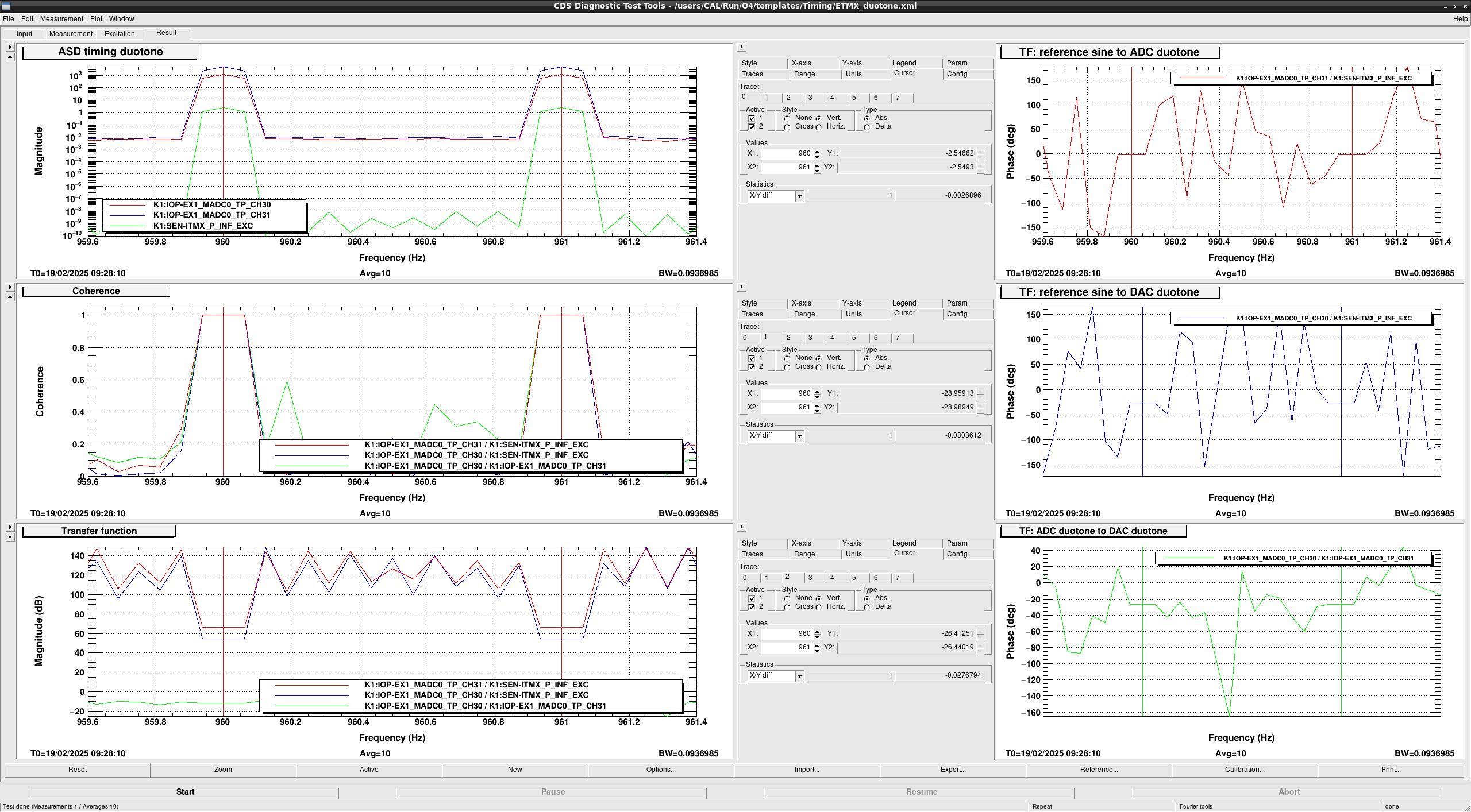
It was evaluated by using the duotone (960Hz+961Hz) timing signal. ADC and DAC have typically ~7.6us and 5/65536s delay, respectively. Timing slave produces the duotone signal as sin(2*\pi*960Hz*t) + sin(2\*pi*961Hz*t). When time, t, is integer number, phase of duotone signal is 0deg. So the delay of ADC and DAC can be seen as the phase of duotone signal on ADC/DAC. We need the reference sine signal that phase is 0 at integer number of time in 65kHz. So I used K1:SEN-ITMX_P_INF_EXC as the 65kHz excitation point and injected simulated duotone signal from this excitation point. Top right panel in Fig.9 shows the phase of TF from reference duotone signal to one on ADC. Phase at 960Hz is ~2.55deg corresponding to ~7.4us delay. It's almost expected. Bottom right panel shows the duotone signal on the ADC to one of DAC output measured on loopback ADC channel. A result is ~26.4deg at 960Hz corresponding to ~76.4us. It's almost 5 samples in 65536Hz (=76.3us).
Conclusion
There is no candidate of unknown ~15us between ADC and DAC. This unknown delay is no impact for online h(t) and the estimation of optical gain and actuator efficiencies. But we need to identify it for the offline h(t) for O4c and to check the analog part of the DARM loop.
