Reports 1-1 of 1 Clear search Modify search
MIF (ASC)
takafumi.ushiba - 13:41 Tuesday 18 February 2025 (32726) Print this report
Compensation filter of ETMY suspension yaw plant for ASC

Abstract:

I made compensation filter to adjust ETMY suspension plant to ETMX one.
The filter was made at FM4 of K1:VIS-ETMY_TM_LOCK_Y filter bank.

Detail:

To achieve the better actuator decoupling of ASC, I made compensation filter for ETMY yaw plant.
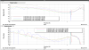
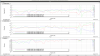
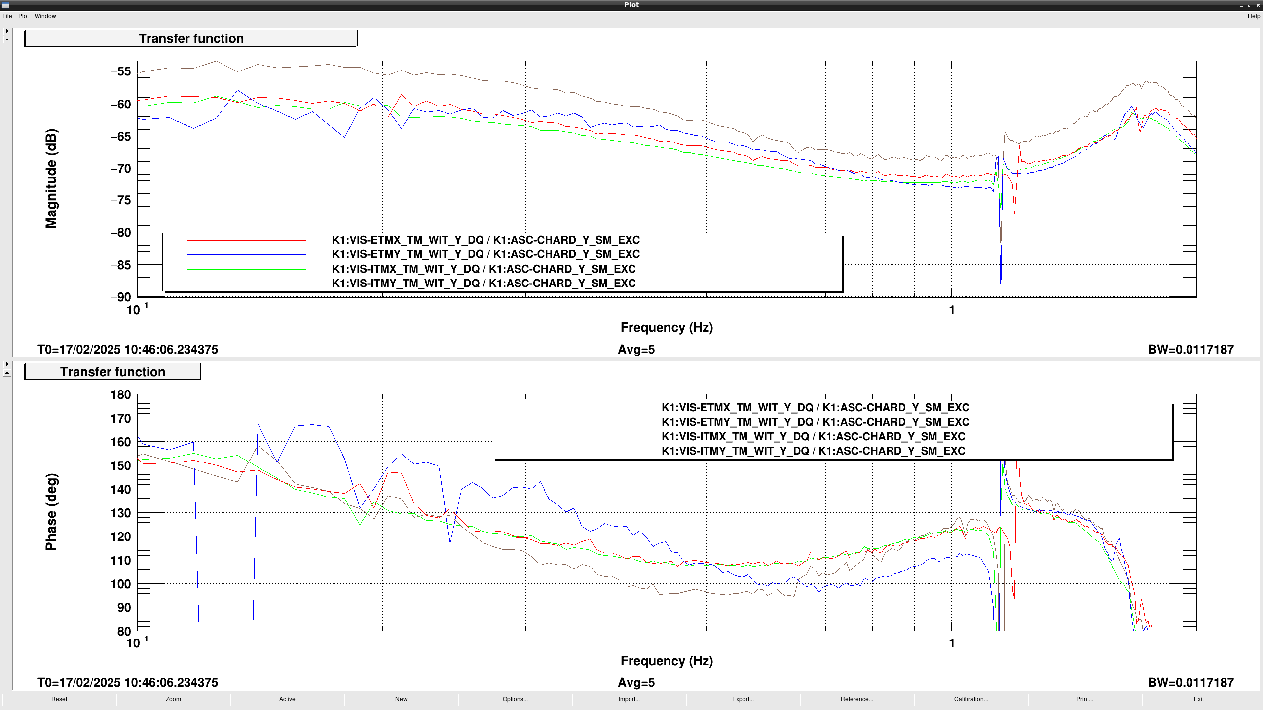
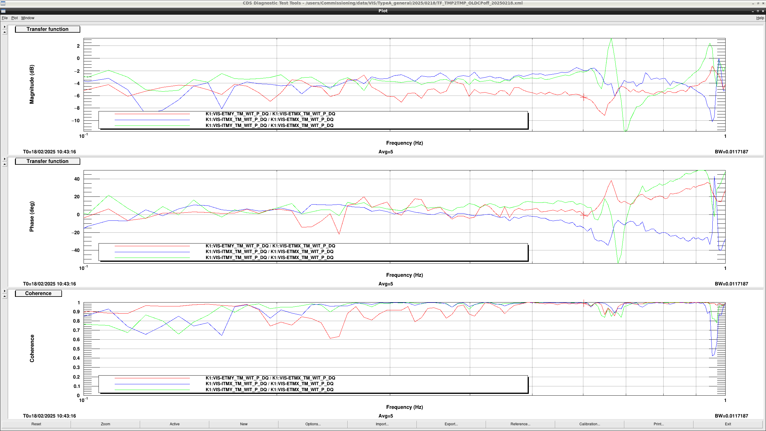
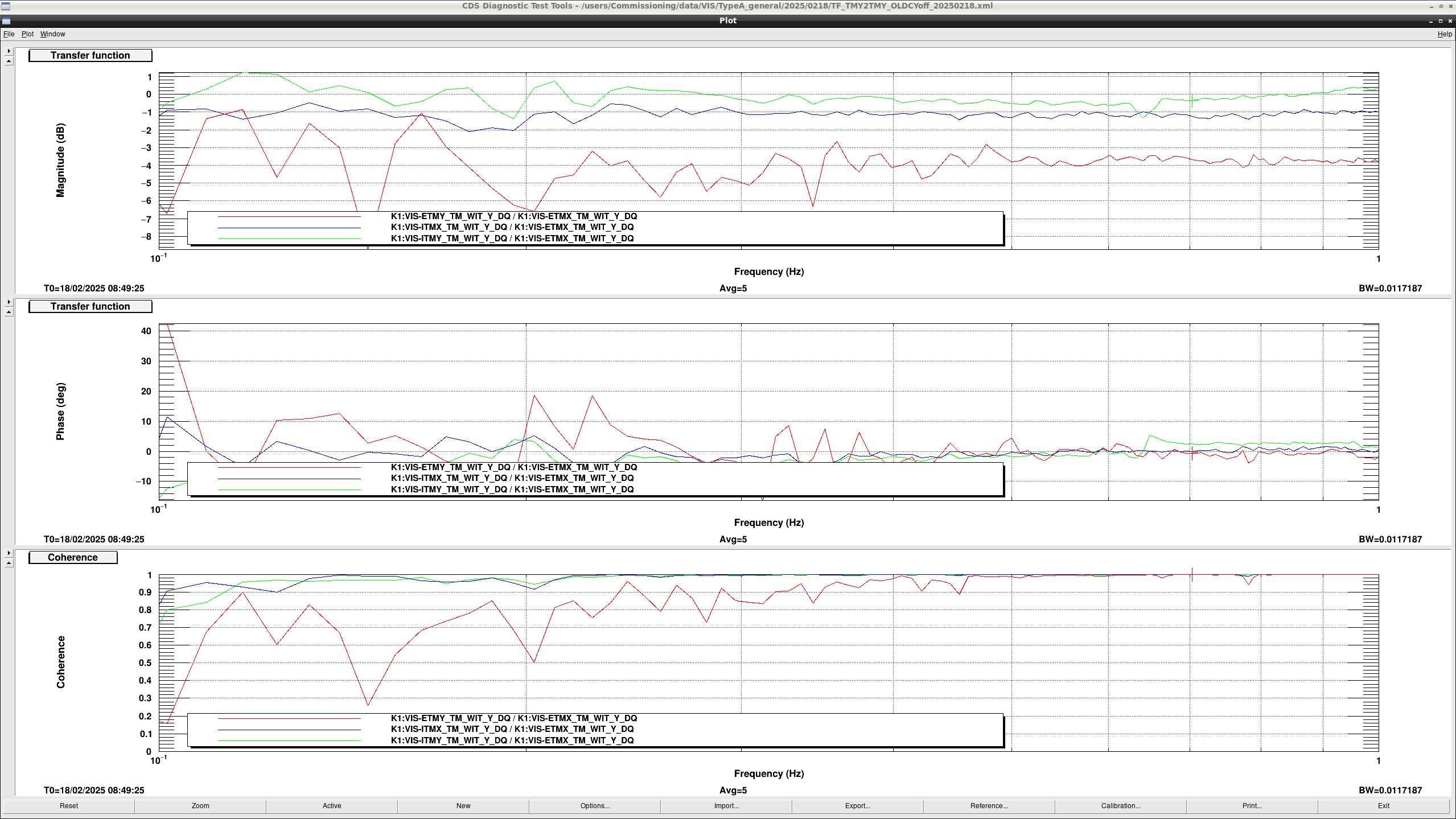
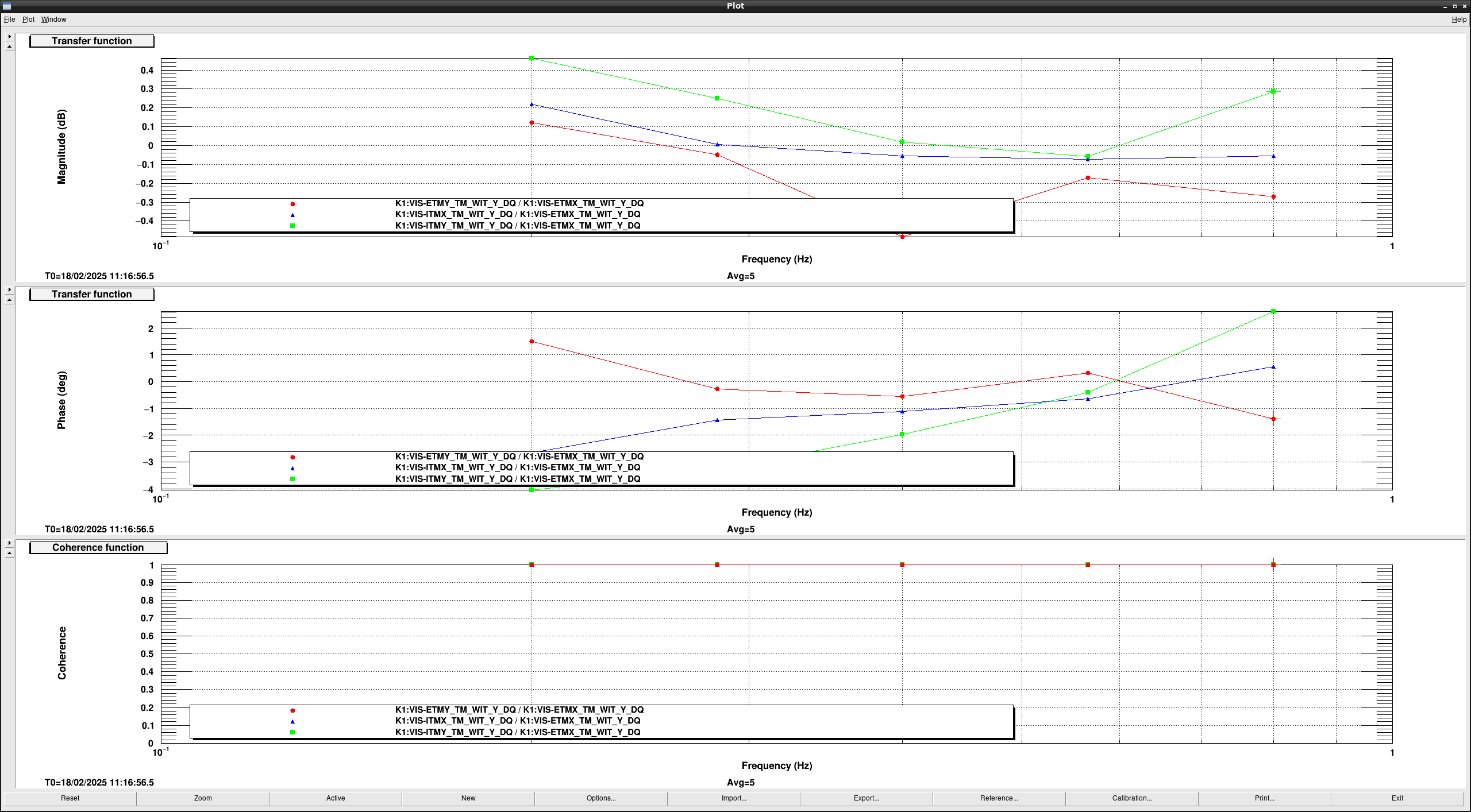
Figure 1 shows the TF from TMY excitation to TMY motion of each test mass.
ETMY has a slightly larger phase difference around 0.3 Hz and 0.8 Hz compared with the other suspensions.
So, I designed compensation filter for ETMY susension plant.

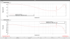
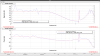
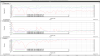
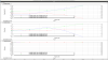
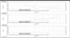
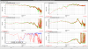
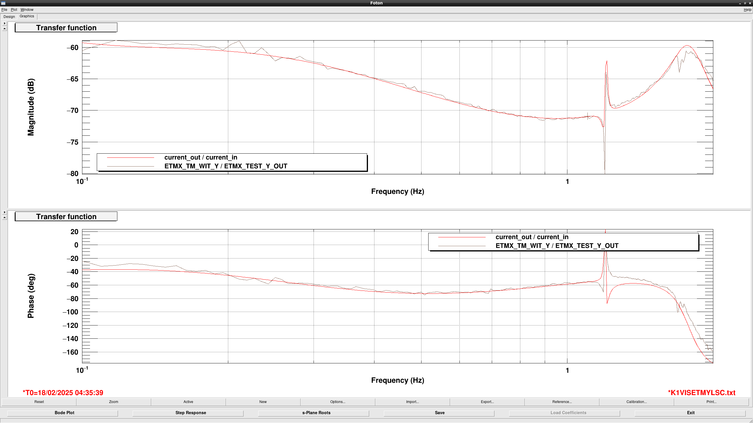
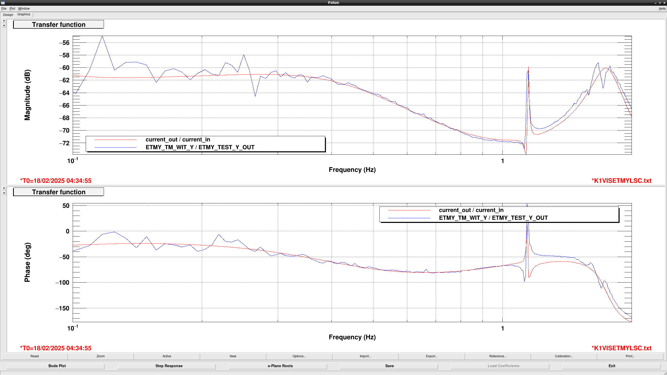
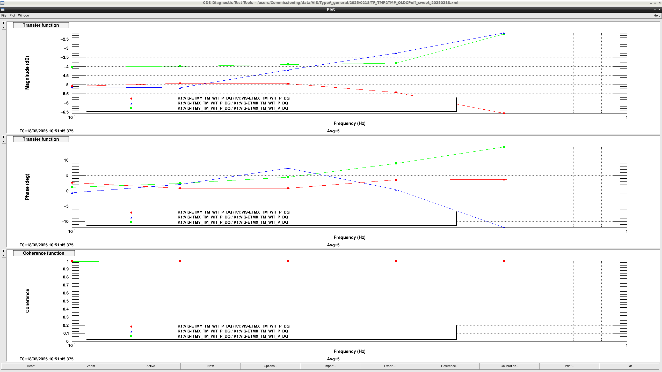
Figure 2 and 3 show the suspension model of ETMX and ETMY I designed, respectively.
Though high frequency gain and phase are slightly different between models and measurement, gain and phase below 1 Hz seems well matched.
Since the current UGF of yaw ASC is 0.6Hz, it should be fine at this moment.

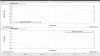
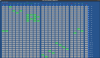
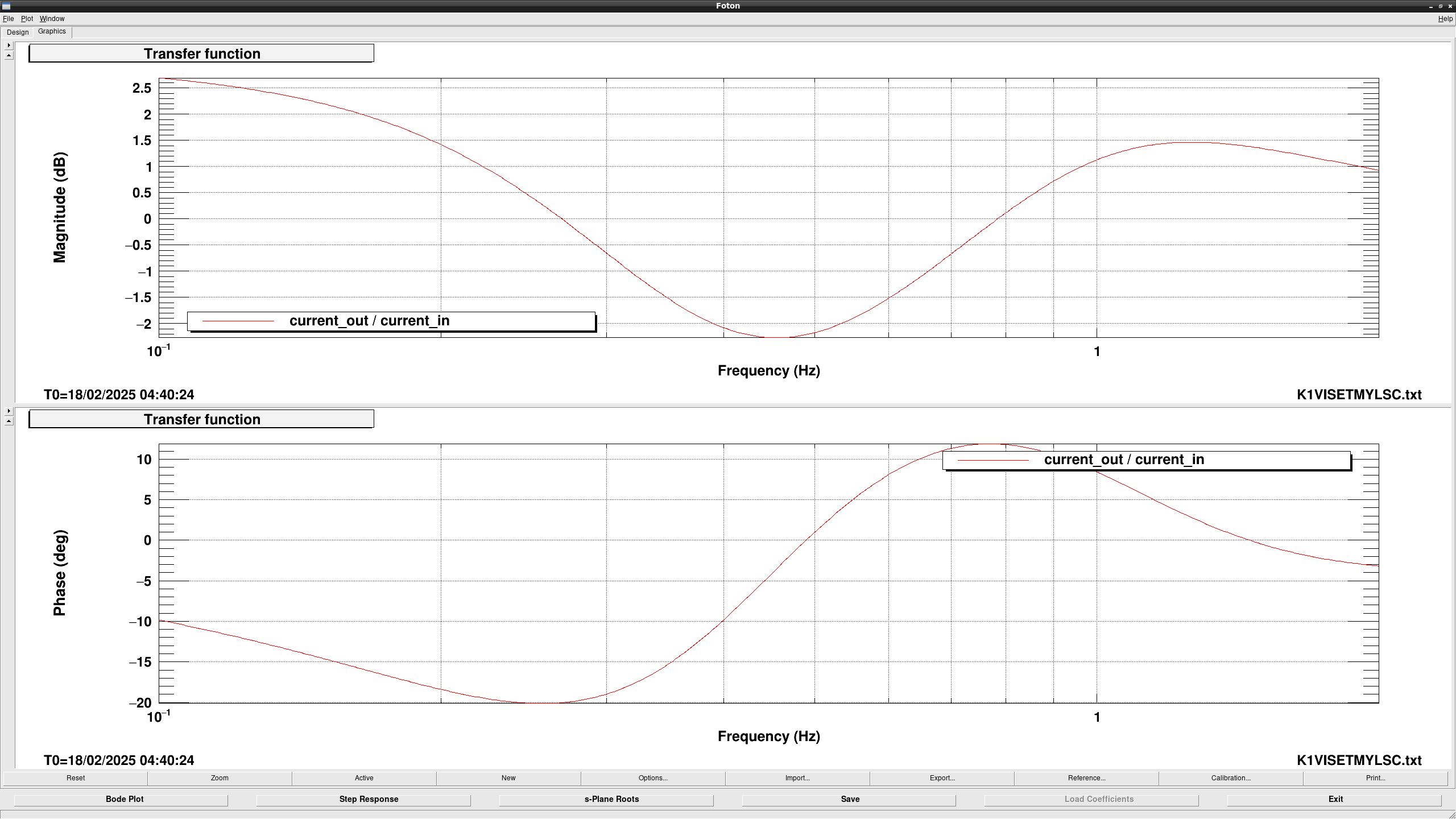
According from the zero-pole vales of the model, I made a compensation filter (fig4).
I will test this filter when I willhave time.

Images attached to this report
Comments to this report:
takafumi.ushiba - 8:55 Wednesday 19 February 2025 (32738) Print this report

Abstract:

Though I adjusted relative gain of TM stage of each Type-A suspension, CHARD TF didn't change significantly.
Next step is to check MN actuator efficiency.

Detail will be posted later.

takafumi.ushiba - 22:46 Thursday 20 February 2025 (32757) Print this report

Detail:

TFs from CHARD_{P,Y}_SM_EXC to TM{P,Y} of each Type-A OpLev were meaasured with compensation filters for ETMY.
Figure 1 and 2 show the ratio and relative phase between ETMX OpLev and the others.

The coherence of yaw measurements seems high around UGF of ASC yaw loop (0.6 Hz), so I calculate the relative actuator gain.
Since the coerence for pitch measurements seems low around UGF of ASC pitch loop (0.2), I performed the same measurement with swept sine excitation (fig3).
According from these results, I calculated the actuator matrix for ASC as shown in fig4 (pitch) and fig5 (yaw).

To check the actuator balance of yaw, I measured yaw TF with swept sine excitation after actuator balancing (fig6).
Thanks to the compensation filter, gain difference is less than +/-0.5dB and phase difference isless than +/-5 degrees, which is much smaller than without compensation filter.

Then, I measured TF of CHARD_Y loop with new balanced actuators to check if the small phase margin around 0.3 Hz was improved or not.
Figure 7 shows the OLTF of CHARD_Y loop.
Though phase delay around 0.1-0.2 Hz seems slightly better than before, phase delay around 0.3 Hz is still somehow large.
Since I only performed actuator balance of TM stage, it would be better to check the actuator balance of MN again.

Images attached to this comment
Search Help
×

Warning

×