Reports 1-1 of 1 Clear search Modify search
VIS (EX)
takafumi.ushiba - 18:00 Friday 10 January 2025 (32310) Print this report
ETMX MN OpLev seems clipped

ETMX OpLev SUM is now about 100 cnts while it was ~10000 cnts before cooling, so I started to investigation.
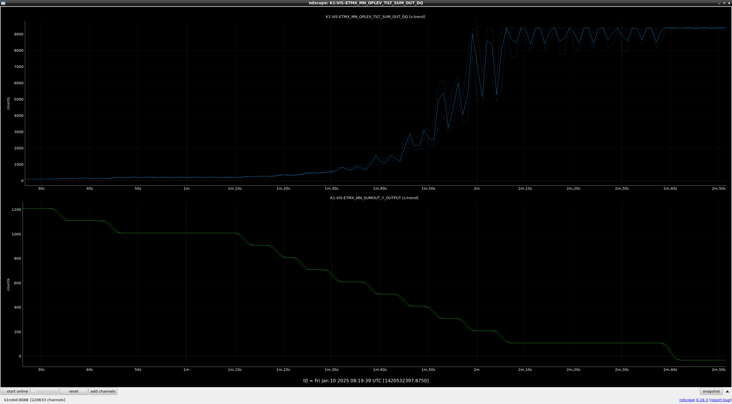
Figure 1 shows the MN OpLev SUM when changing the MN Optic align values at PAY_FLOAT state.
When MN Optic align values are -1200 cnts from the aligned position, MN OpLev SUM is more than 9000, which implies that MN OpLev beam is clipped somewhere.

Since the cooling would change the relative angle between TM and MN, this phenomena can happen even if we kept the good alignment of ETMX.
What we can do depends on the situation:
1. If the clipping happens on the BS of the detection port, we can recover it by realigning the optics on the reciever side.
2. If the clipping happens inside the cryostat, we need to move injection beam to recover the clipping.

Anyway, ETMX MN OpLev damping performance getting worse and it is dificult to lock the interferometer stably in this condition, so we need to fix the probem.

Images attached to this report
Comments to this report:
takafumi.ushiba - 18:57 Tuesday 14 January 2025 (32331) Print this report

[Tanaka, Yokozawa, Ushiba]

Abstract:

We moved injection beam path of ETMX MN TILT OpLevs.
Also, we performed centering of MN OpLevs.

Detail:

We checked the MN TILT OpLev beam at reciver side and found that the beam shape coming out from the viewports were already clipped (fig1).
So, we moved injection beam to recover the clipping, and then the QPD SUM values were also recovered.

We also checked the MN ROL OpLev beam and it didn't seem to be clipped, so we didn't move the injection beam for MN ROL OpLev.

After that, we centered all MN OpLevs (MN LEN, MN TILT, MN TRA, MN ROL, and MN VER).

Images attached to this comment
kenta.tanaka - 19:16 Tuesday 14 January 2025 (32332) Print this report

The spectra of {MN,TM} Oplev signals in LOCK_ACQUISITION are shown in fig.1, blue lines are the spectra before the adjustment, and red lines are after the adjustement. As you can see, the MN TILT/LEN oplevs see the suspension motion in the TILT and LEN directions, respectively. Thanks to this, the 1 Hz peaks in TM PIT and YAW are well damped.

On the other hand, the peaks around 2 Hz in MN/TM oplevs can be seen. We may need to adjust the damping filters.

Images attached to this comment
Search Help
×

Warning

×