## What we did on this Christmas
### solved the oscillation at ~150 kHz
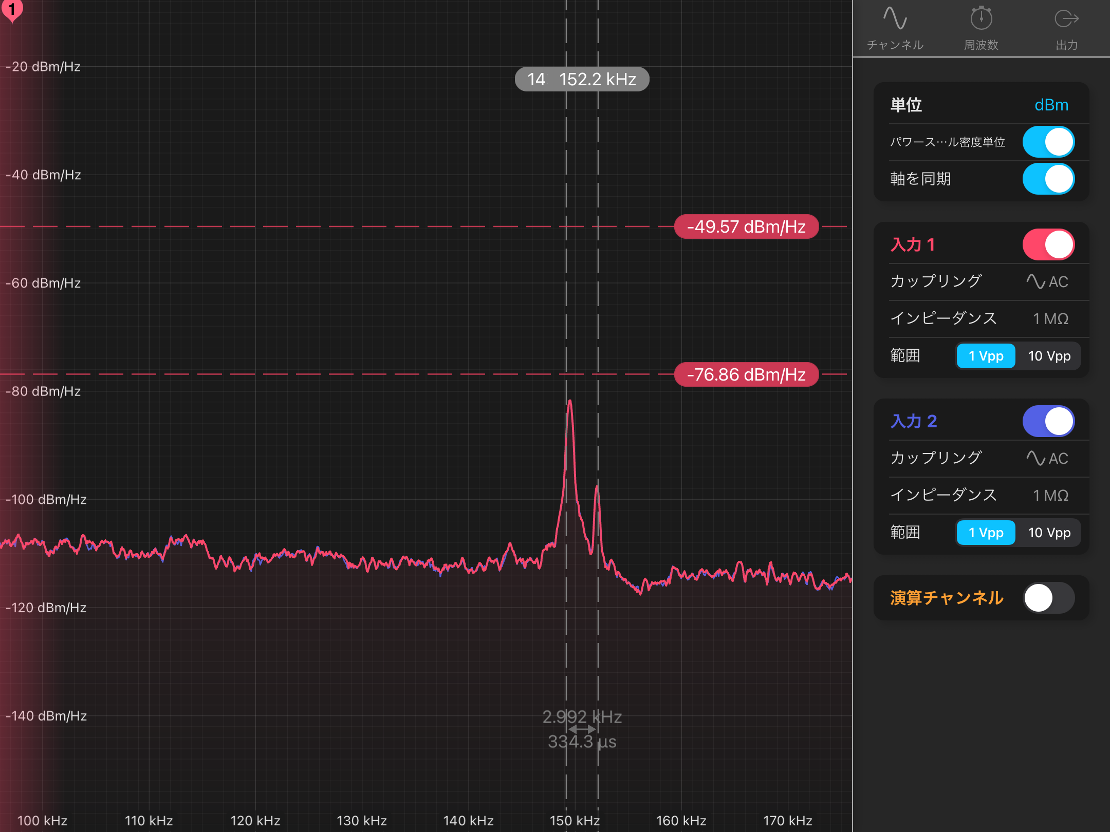
First, we measured the OLTF of the IMC loop more finely. Fig. 1 shows the result, and Fig. 2 shows the one zoomed up around 150 kHz. The shapes are seen in the TF around 150 kHz and the peak at about 150 kHz crosses 0 dB. Also, we measured the spectra of the signal above 100 kHz at TEST A and B ports on the MC servo with Moku:lab (Fig.3). There seem to be two peaks at 149 kHz and 152 kHz. The amplitude of the 149 kHz peak was breathing from -76.9 dBm to -49.6 dBm, on the other hand, the one of the 152 kHz seems not to be changed so much.
Then, we tweaked the IMC servo's common gain (IN1GAIN) to confirm whether the shapes in the OLTF around 150 kHz caused their peaks. As a result, the 149 kHz peak grew when we increased the gain, and when we decreased the gain, the 149 kHz peak decreased and disappeared. Therefore, the peak was caused by the oscillation. However, the 152 kHz peak was not changed.
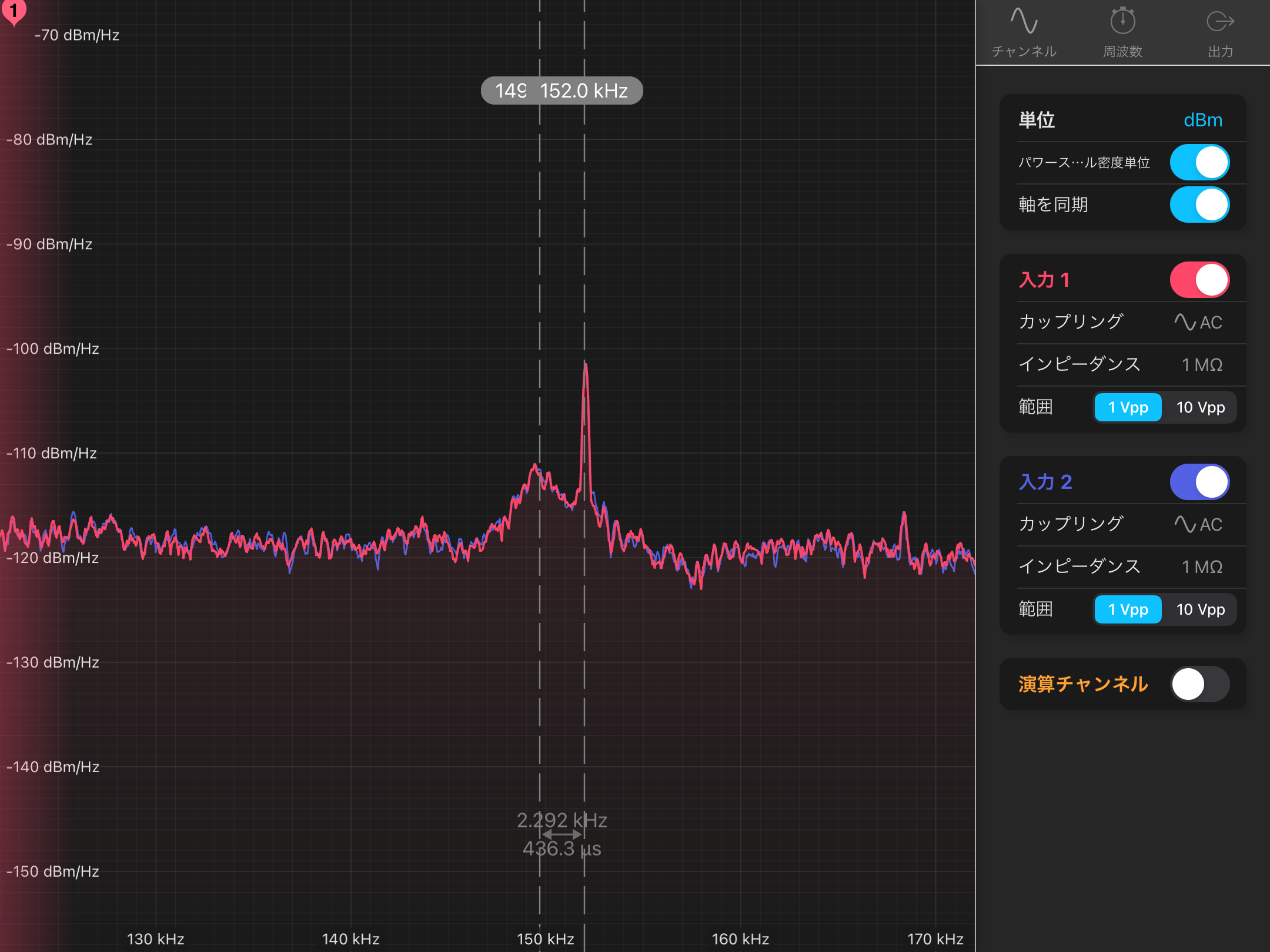
Next, we tried to decrease the cross-over frequency between the PZT loop and the EOM loop by decreasing the common gain to - 6dB and increasing the gain of the EOM loop (FASTGAIN) to keep the overall UGF at 100 kHz. The cross-over frequency in this state decreased from 18 kHz to 10 kHz (fig.4). Then, the 149 kHz peak disappeared from the spectra measured with Moku:lab (fig.5) and noise floor level also decreased. This indicates that the PZT loop gain seems to be too high even though the relative phase margin around 150 kHz between the PZT loop and the EOM loop became small in the PZT and EOM setup of current HPL maybe because of the resonance of the EOM crystal or something. However, the 152 kHz peak still remains. So the cause of this peak seem to differ from the 149 kHz. But the peak height is smaller than the 149 kHz. Fig. 6 shows the IMC OLTF in this setup. The shapes around 150 kHz were -1.5 dB. it seems to be so-so.
After that, we locked the Y-arm to confirm whether the 330 Hz peak disappeared or not in this setup. In this time, we increased the common gain to 6 dB to compensate the DC gain by decreasing MC IN1GAIN and also we increased the MCL gain from 0.45 to 1 to keep the cross-over frequency between MCL and PZT loops at ~100 Hz because we decreased the PZT loop gain.
In this state, we measured the spectra related to MC and CARM servos. Fig. 7 shows the results. The measurement configuration was summarized in following table.Magenta lines shows the spectra before our work. Brown lines shows the ones after MC gain adjustment. As you can see, the peaks around 330 Hz still remains, on the other hand, the noise levels seem to become low and the bump around 200 Hz seem to be disappered. Green lines show the one when we increased the common gain. Then, the 330 Hz peaks disappered. Furthermore, Blue lines show the ones when we restored the MC gain to the default gain. The peaks around 330 Hz seems to still be disappeared but the noise levels of CARM_SERVO_{MIXER,FAST,SLOW}_DAQ_OUT become higher. At last, red lines show the ones when MC loops was optimized about 150 kHz oscillation and CARM common and MCL gain were increased. As you can see, the peaks around 330 Hz were disappeared and noise levels became low. And fig. 8 shows the spectra of MC TEST A and B ports. The 152 kHz peak seems to be disappeared.
These indicates the 330 Hz peaks seems to be caused not by the 149 kHz oscillation but by the low UGF of YARM relative to MC loops. However, it is true that the 149 kHz oscillation increased noise levels. Therefore, we need to tune the CARM UGF for the MC loop with HPL, similarly.
| plot label (color) | REF0-9 (magenta) | REF10-19(brown) | REF20-29(green) | REF30-39 (blue) | no tag (red) |
| IMC-SERVO_IN1GAIN | 22 dB (default) | 16 dB | 16 dB | 22 dB | 16 dB |
| IMC-SERVO_FASTGAIN | 24 dB (default) | 30 dB | 30 dB | 24 dB | 30 dB |
| CARM_SERVO_IN1GAIN | 10 dB (default) | 10 dB | 16 dB | 16 dB | 16 dB |
| LSC-MCL_GAIN | 1 (default) | 1 | 0.45 | 0.45 | 1 |
### PRFPMI lock trial
We tried to PRFPMI lock to confirm whether the peaks around 330 Hz still are in the DARM sensitivity or not. However, the IR flash amounts in both arm cavity in sweeping CARM offset seemed to be too low (~20) to surpass the threshold for the handover from ALS to IR. We're not sure of the reason but we have no time to investigate it. So we gave up to see the DARM sensitivity with HPL and switched back to the fiber laser.
## Next
- Investigate the failure of the PRFPMI lock acquisition with HPL (CARM RMS too large? or CARM and DARM offset too far?)
- 330 Hz peaks check with DARM sensitivity and try to tune the CARM UGF to decrease them if their peaks appear in DARM


