Reports 1-1 of 1 Clear search Modify search
IOO (OMC)
kentaro.komori - 19:03 Monday 11 November 2024 (31581) Print this report
OMC DC PDs probably burned

[Komori]

Abstract:

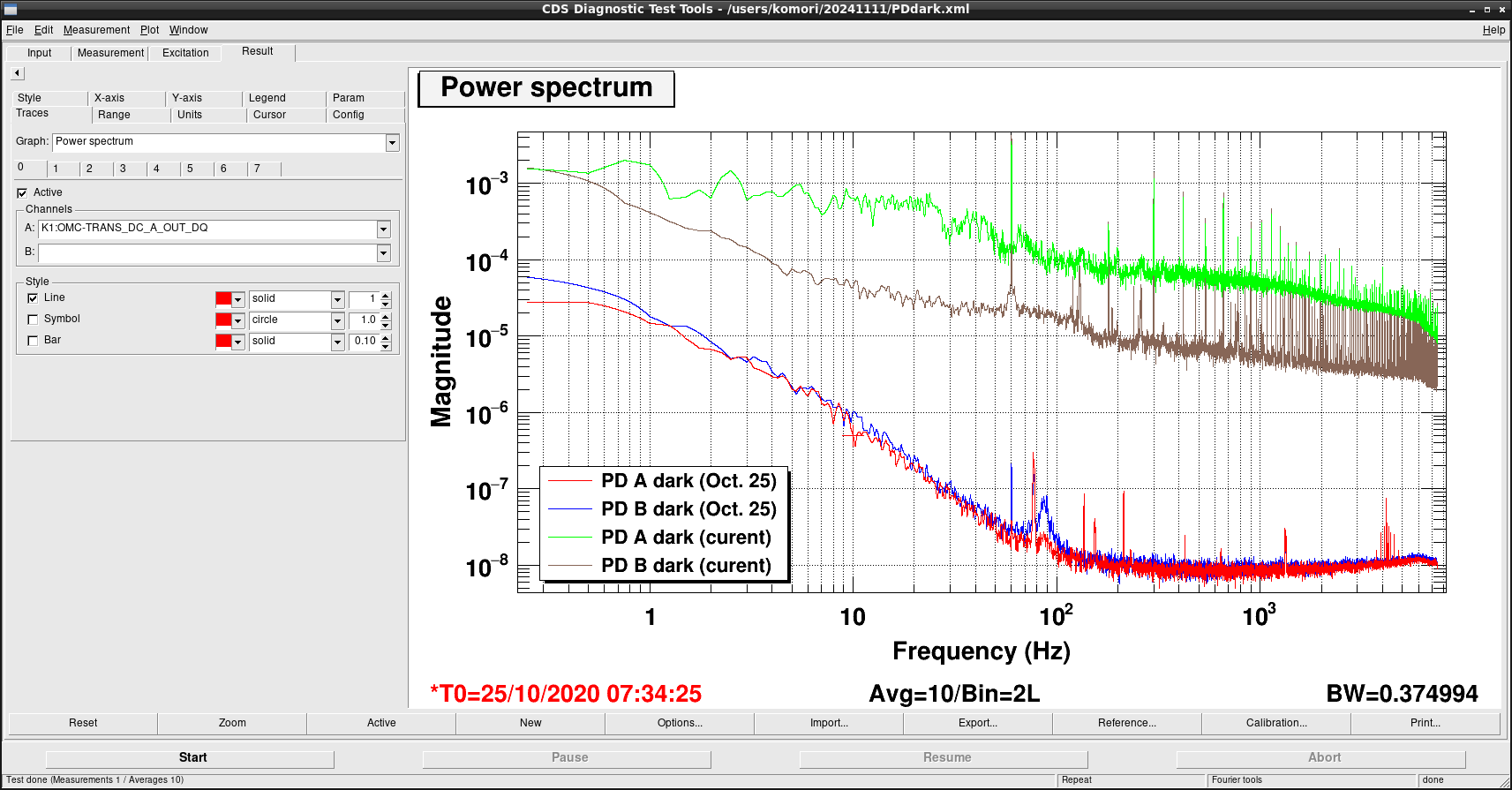
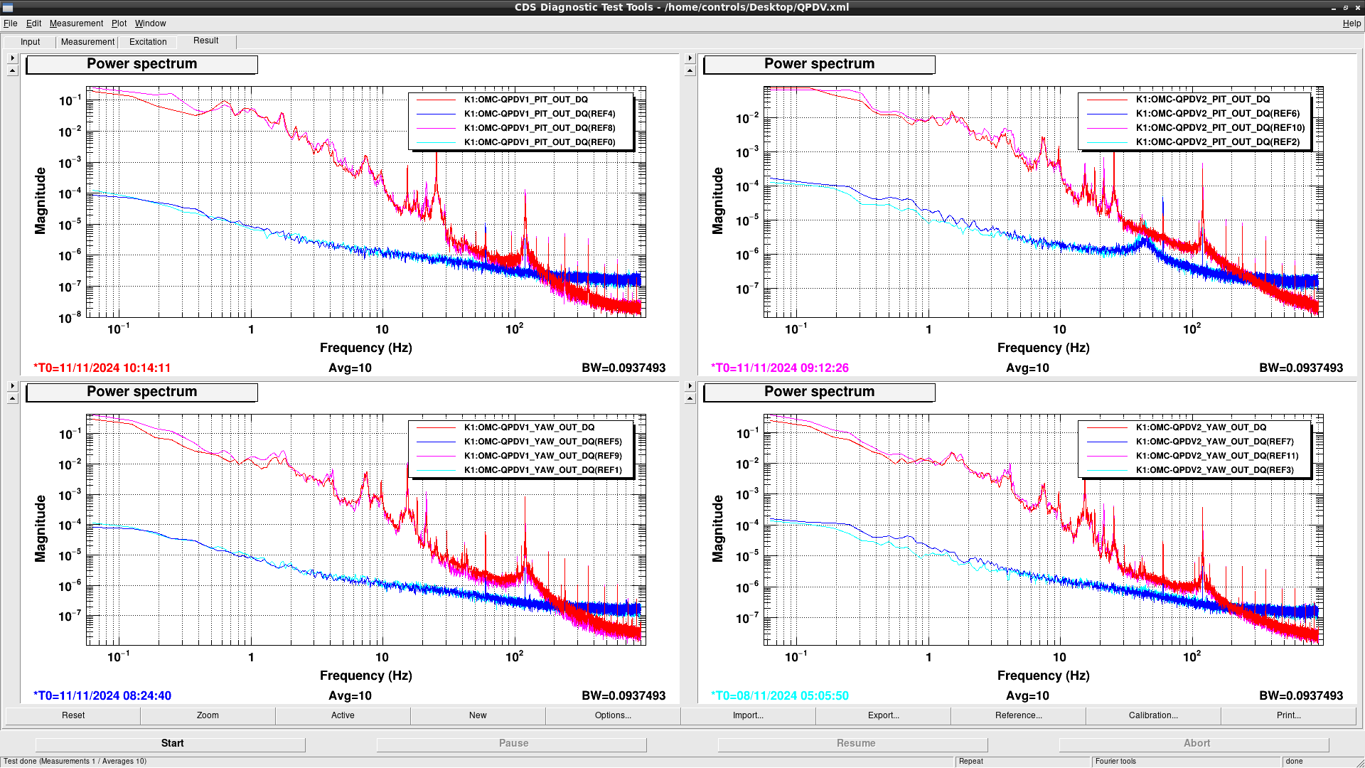
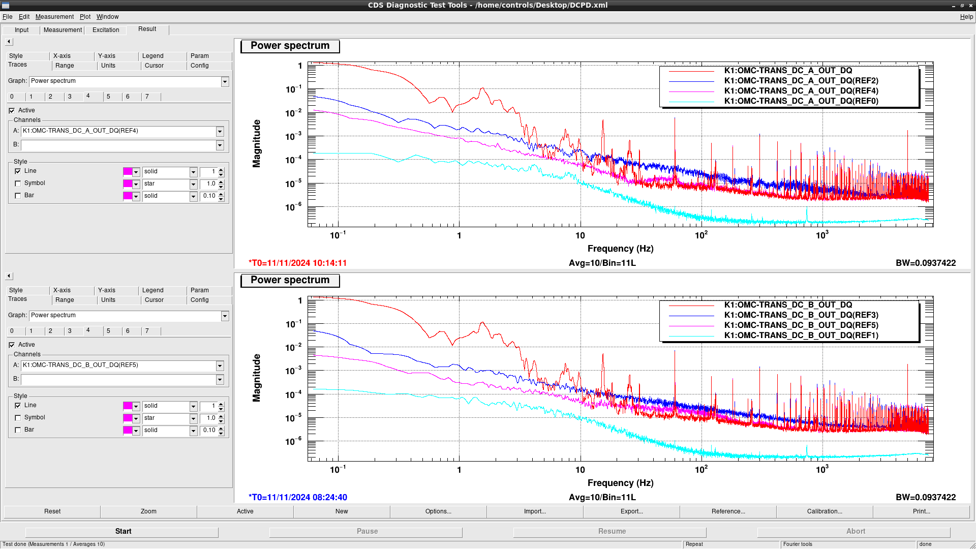
I probably damaged two OMC DC PDs by oscillating the DARM control with an excessively high feedback gain.
As a result, the DC PDs now show abnormal DC outputs that are significantly higher than their nominal values.
We confirmed that the PRFPMI_RF_LOCKED state was restored without any issues.

Detail:

After increasing the input power to the IFO up to 5 W, I tried to reduce the DARM offset to examine its power dependence by manually adjusting the offset and gain.
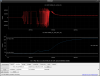
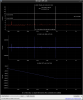
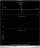
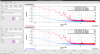
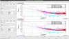
I accidentally input a gain of 061 instead of the intended 0.61 for LSC-OMC_DC, causing the DARM to oscillate, which led to the IFO losing lock.
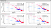
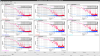
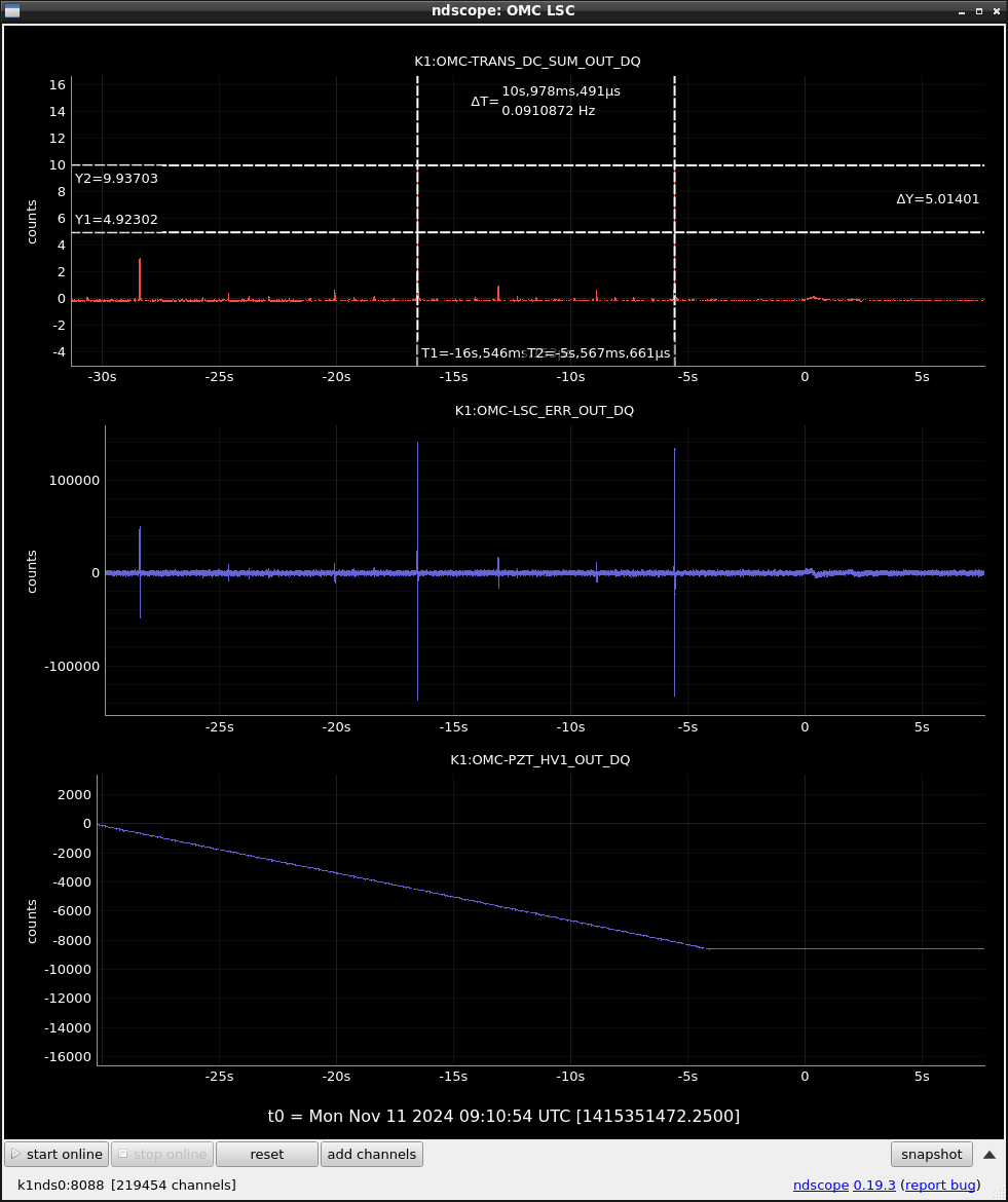
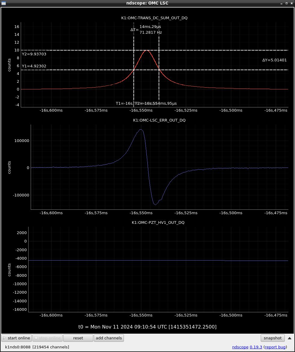
The attached time-series data captures this event.

Following this, the outputs from the two DC PDs (OMC-TRANS_DC_A/B_IN1) exhibited anomalously high values exceeding 10000, and 110 in OMC-TRANS_DC_SUM_OUT.

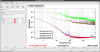
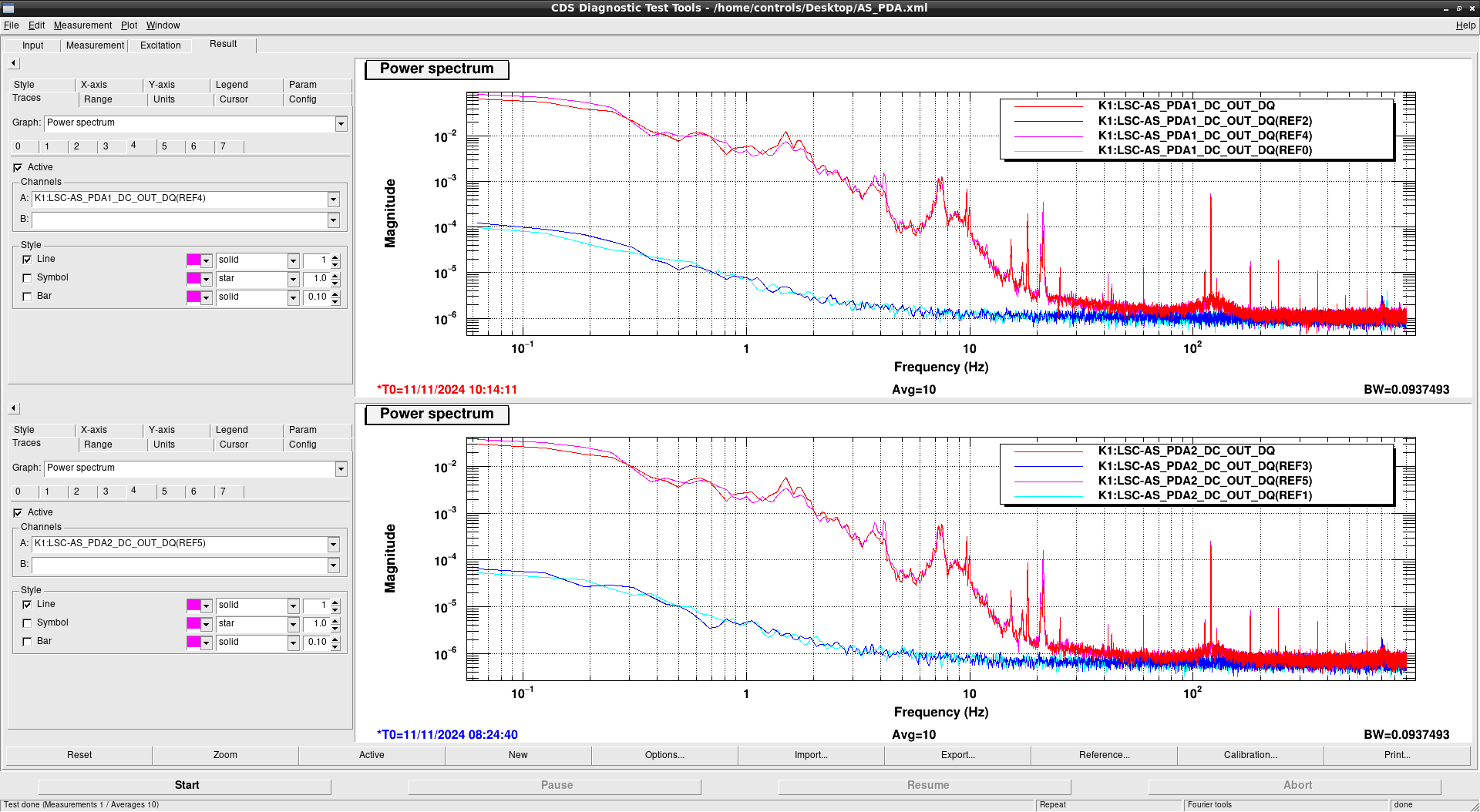
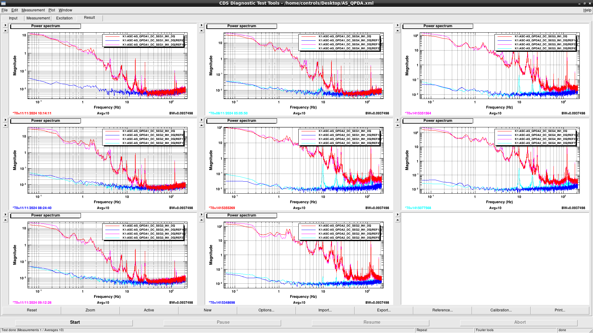
We have confirmed that the PRFPMI_RF_LOCKED state was successfully recovered, suggesting that the RF optics at the AS port are probably not damaged.
The OMC finesse remains unchanged, which will be detailed in a subsequent report.

Images attached to this report
Comments to this report:
kenta.tanaka - 19:22 Monday 11 November 2024 (31582) Print this report

Komori, Tanaka

We roughly measured the finesse of OMC with the cavity scan to chack whether the mirror surface is contaminated by the PD burning.

After PRFPMI RF lock with 1 W input power and engaging the nominal DARM offset, and we temporaly subtracted the current offsets on invac PDs with K1:OMC-TRANS_DC_{A,B}_OFFSET. We found that we could see the OMC trans. flash with the current OMC TRANS PDs. At that time, the amount of TEM10 flash was largest due to the bad alignment to OMC. We used this mode to obtain the finesse.

Fig. 1 is the timeseries of OMC trans. PD, the time range between the one of TEM10 flash and the another TEM10, which is represent with FSR, seems to be 11s. Fig. 2 is the one zoomed in fig.1. the time range which is represent FWHM seems to 14ms.

Then, we roughly estimated the current finesse 11s/14ms = 786. According to klog20764, the current OMC finesse is close to the previous one (~813). Therefore the mirror themselves may seem to be fine.

After this measurement, we restored the value in K1:OMC-TRANS_DC_{A,B}_OFFSET.


Images attached to this comment
kentaro.komori - 19:57 Monday 11 November 2024 (31585) Print this report

[Tanaka, TYamamoto, Komori]

We measured the current dark noise of the two DC PDs suspected to be damaged.
For reference, we compared these measurements with the dark noise data from October 25th of this year, taken at a similar time when the dark noise was recently measured, as recorded in the klog:31433.
We confirmed that the IR shutter was closed during that previous measurement.

The results clearly show that the current dark noise is significantly worse than the previous measurement.

Images attached to this comment
takahiro.yamamoto - 20:09 Monday 11 November 2024 (31583) Print this report

I checked spectra of AS PDs in following cases.
Red: RF lock after this issue [today's evening]
Magenta: RF lock before this issue. [today's afternoon]
Blue: IMC output is 0 after this issue (shutter is not closed) [today's evening].
Cyan: IMC output is 0 before this issue (shutter is not closed) [Friday's afternoon].

AS_PDA1, AS_PDA2 (Fig.1), OMC_QPDV1, and OMC_QPDV2 (Fig.2) seem to be no problem.

According to Fig.3, AS_QPDA1 also seems to be no problem.
Though 10Hz peak series can be seen on AS_QPDA2 in last Friday, it cannot be seen now.
On the other hand, there is no difference in the case of RF lock before and after this issue.
So absence of 10Hz peak series seems to be caused by the some kind of improvement in the environment not a broken PDs by this issue.

So affected PD seems to be only DCPD (Fig.4).

I put all results in /users/Commissioning/data/IFO/2024/1111.

Images attached to this comment
kenta.tanaka - 11:14 Tuesday 12 November 2024 (31597) Print this report

We added some PD outputs (AS PDA1 RF17/DC, OMC QPD1,2 SUM) around the burned moment in order to look into the power monitor used as the protection trigger (fig.1). At the moment on the left cursor, DARM oscilation could be seen in the inputs of OMC TRANS PDs, then their inputs was satulated soon. After 76 ms, at the moment on the right cursor, AS PDA1 DC output in middle panel of  fig.1 drastically increased to 8 mW. The ususall RMS of AS PDA1 (< ~0.1 mW) seems to be much smaller than this power increasing. so we can use AS PDA1 DC output as the trigger channel.

## Note

OMC QPD SUMs have no fast channels. if fast channels are implemented, OMC QPD SUMs also can be used as the trigger.

Images attached to this comment
Search Help
×

Warning

×