Reports 1-1 of 1 Clear search Modify search
CAL (General)
hirotaka.yuzurihara - 16:50 Tuesday 03 September 2024 (30958) Print this report
Construction and demonstration of TCam test bench

Today, I constructed the TCam test bench by adding Baader's prism and three quick releases by Baader (they can be used as the rotator). I demonstrated it in the mine. The details are summarized on the side(JGWdoc).

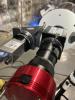
  • Fig1 shows the TCam test bench.
  • I checked the size of the expanded camera and confirmed we could install it in the current TCam box. 
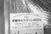
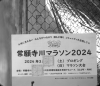
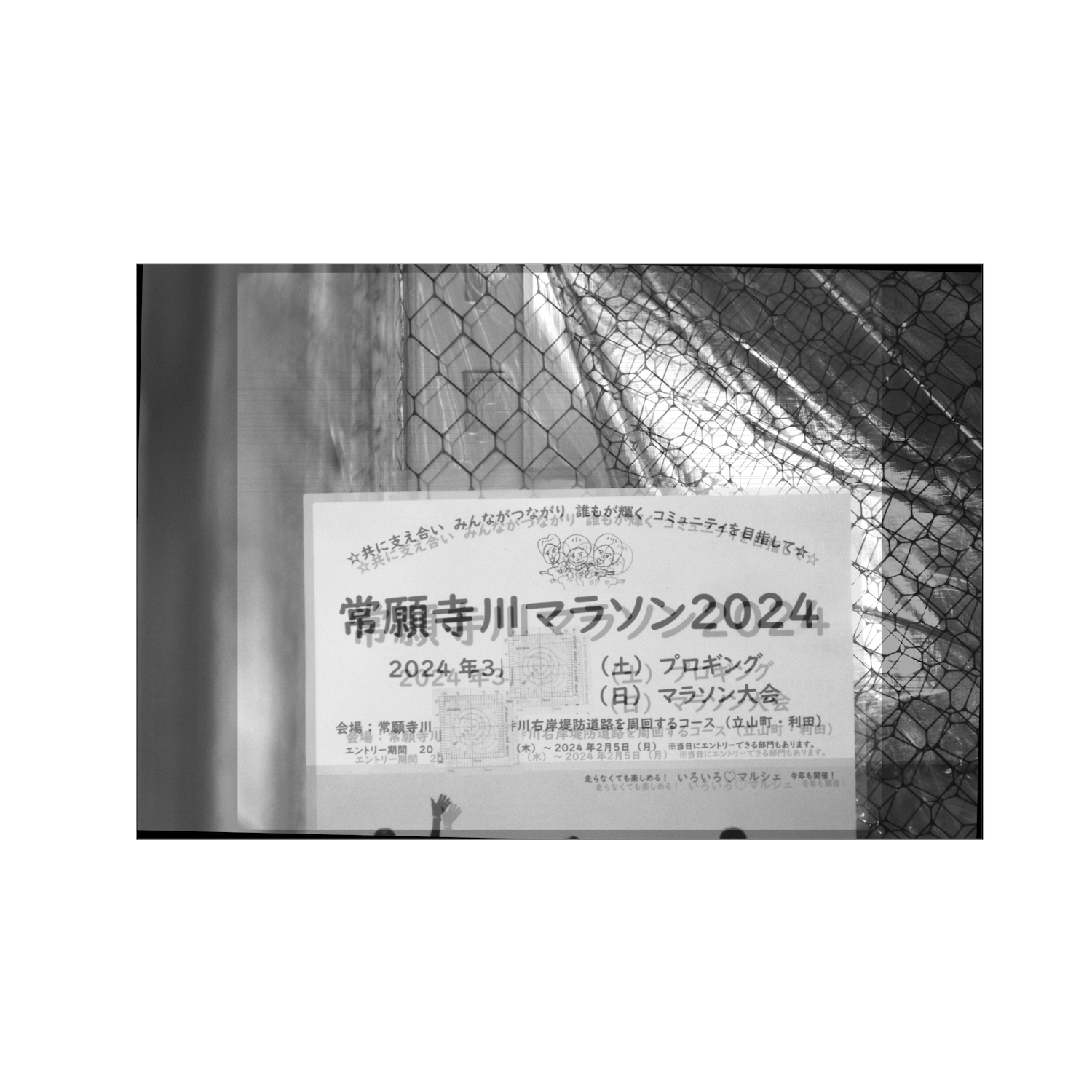
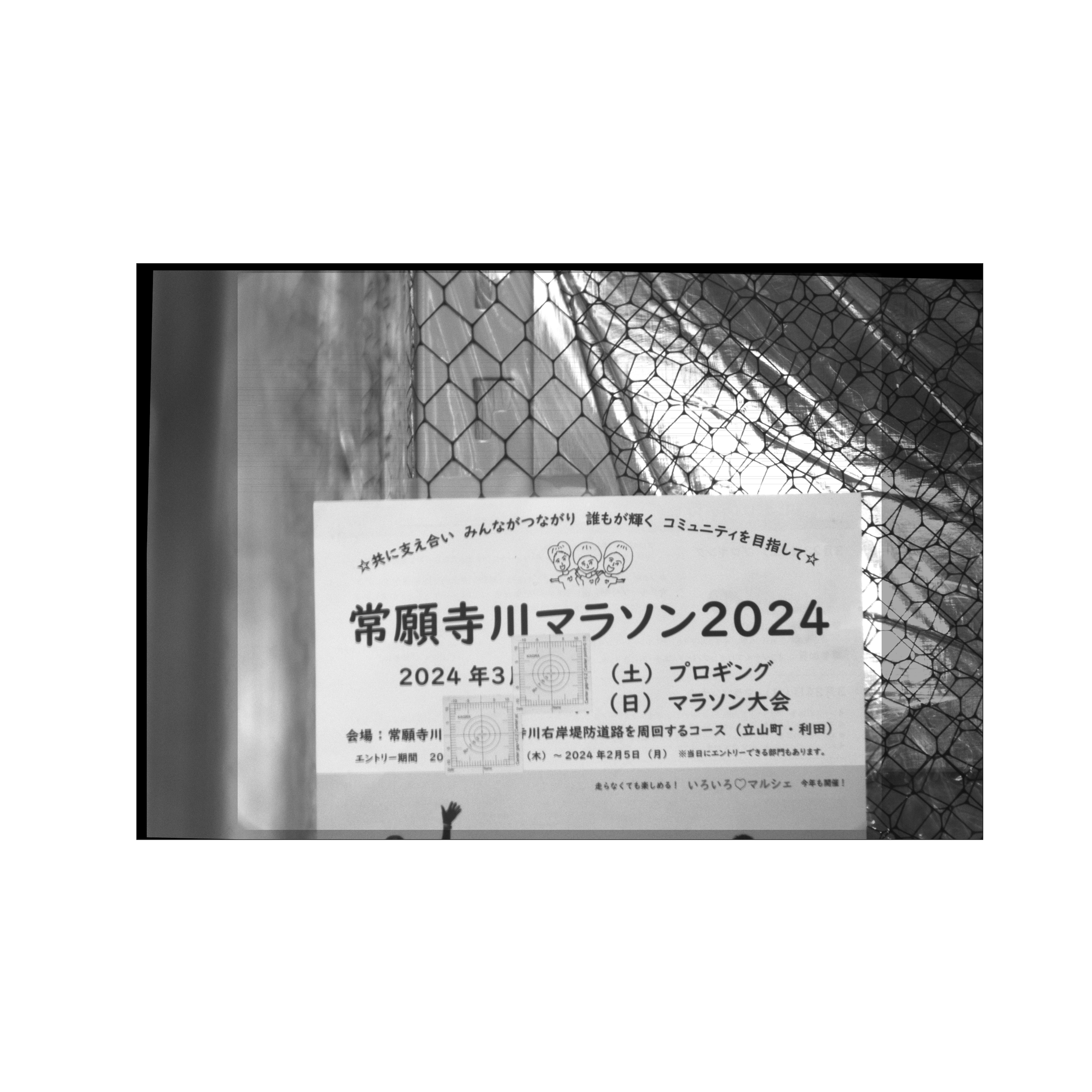
  • The image centers of the two cameras are almost consistent within a few mm (see Fig2). I took the image with the ~30 m distance.
  • The newly added prism corporates increase the maintainability. All the components are accessible from one side. 
  • Initially, we thought we could control the camera's horizontality using the leveler. It might not be easy...
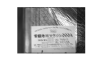
  • I also took several images by changing the optical path for the ASI camera.
  • Kashima-san (Aogaku) helped with this work during her Kamioka stay.
Images attached to this report
Comments to this report:
hirotaka.yuzurihara - 23:58 Tuesday 10 September 2024 (31048) Print this report

I analyzed the images taken and evaluated the relationship between the two images using Affine transformation. The images match very well when we rotate the ASI image by -1.5 degrees and perform the parallel shift of +85 pixels horizontally and +65 pixels vertically. We confirmed that the accuracy of the test bench construction is at an acceptable level that does not affect the analysis.

Details

  • Fig1: the image taken by the ASI camera.
  • Fig2: the image taken by the gige camera.
    • Due to the file size and format limitations, the uploaded images are smaller than the original ones. I also converted from TIFF format to PNG format.
    • The setup of the test bench can be seen on the slide.
  • The image size and the image sensor sizes are different due to the different cameras. To compare the images fairly, I added the black blank to the gige image to be the same image sensor size as the ASI camera. After that, I resize the ASI image (similar to up-sampling). As a result, two images have the same size (4768, 7002).
  • Fig3: the overlay of two images with same size, before the transformation. 
  • I performed an Affine transformation and looked for the best rotation angle and the parallel shift.
    • We rotate the ASI image by -1.5 degrees. Fig4 shows the overlay of two images after the rotation.
    • We perform the parallel shift of +85 pixels horizontally and +65 pixels vertically.  Fig5 shows the overlay of two images after the parallel shift. The images match very well.
  • By counting the number of pixels of the 10mm target around the center of Fig2, which Tomaru-san provided, the conversion factor between the pixel and the actual length could be evaluated as 10/261.15=0.038mm/pixel.
    • So, the 85-pixel shift is almost 3.3 mm, and the 65-pixel shift is 2.5 mm. This difference is slight compared with the mirror size and image size.
  • When we install this new camera in the TCam system and take images with two kinds of cameras, we need this kind of correction every time. At that time, it's good to do these steps automatically. We can probably use several characteristic appearances in the images.
Images attached to this comment
Search Help
×

Warning

×