Miyakawa, Takano, Tanaka
This is a log about works done on 7/25 (Thu), related to this post.
Abstract
We fixed our mistake done in the prevous work. After tuning the polarization to EOM1 to almost s-pol, RFAM level seems better than before.
Detail
In the work done on Tuesday, we tuned the input polarization to EOM1 as almost p-pol (klog 30531). However, we found that this work was done with a reference which didn't make sense (klog), and actually this polarization setting was totally wrong (klog 30541, klog 30550).
Today we tried tuning the polarization around s-pol and checked the RFAM level.
Pure s-pol preparation
We tuned the input polarization as pure s-pol again, by using a pair of HWP and QWP in fromt of EOM1. The angle of HWP read about 270 deg, which was consistent with the work on Tuesday. After that, we checked the power ratio of the reflection and transmission at the PBS in front of RFAM monitor with a sensor card and tried to minimize the reflection power. However, we found that it was hrad to minimize the power reflected by the PBS so that we could not see thie light with a sensor card. This means that the light going to this PBS has some ellipticity. We didn't measure the ellipticity and are not sure when the light gets the ellipticity (EOMs or the lens at which this light was picked off?). We also checked the maximum DC power, and removed a ND filter before RFAM monitor to increase SNR.
Next, we changed the wave plates a little bit around s-pol, and confirmed that the height of peaks changed according to the angle of the wave plates.
RFAM after EOM1
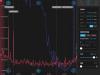
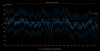
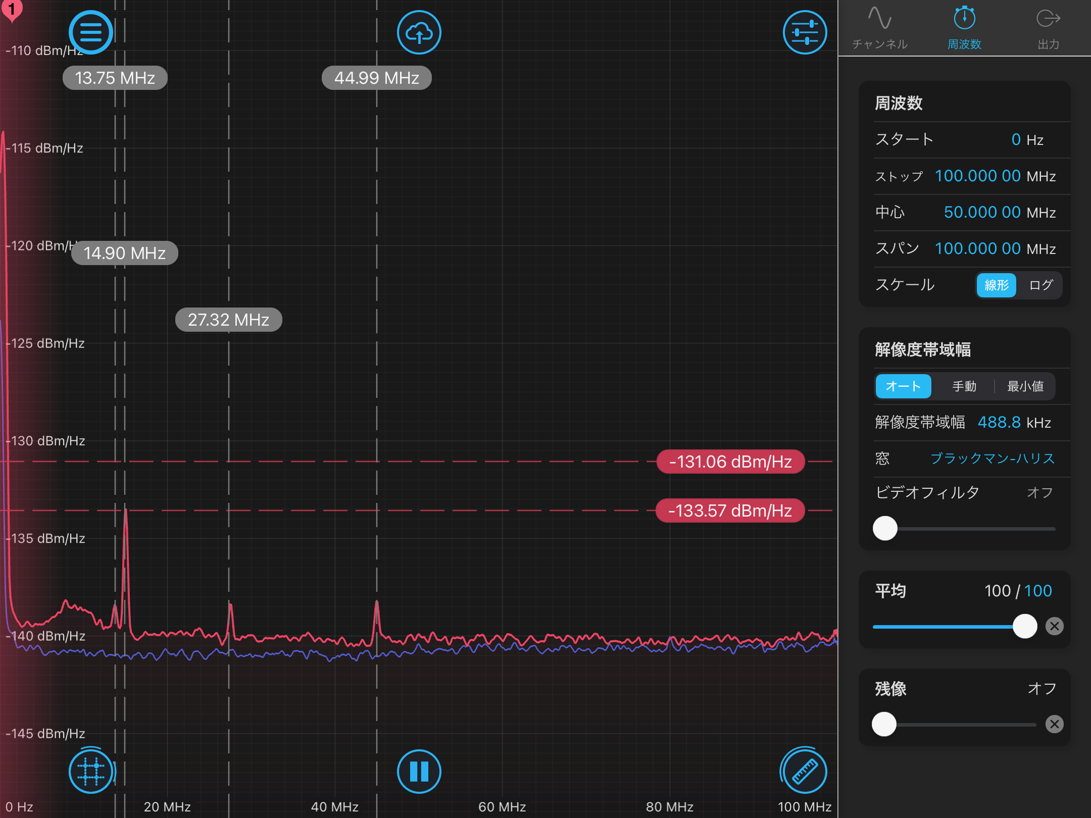
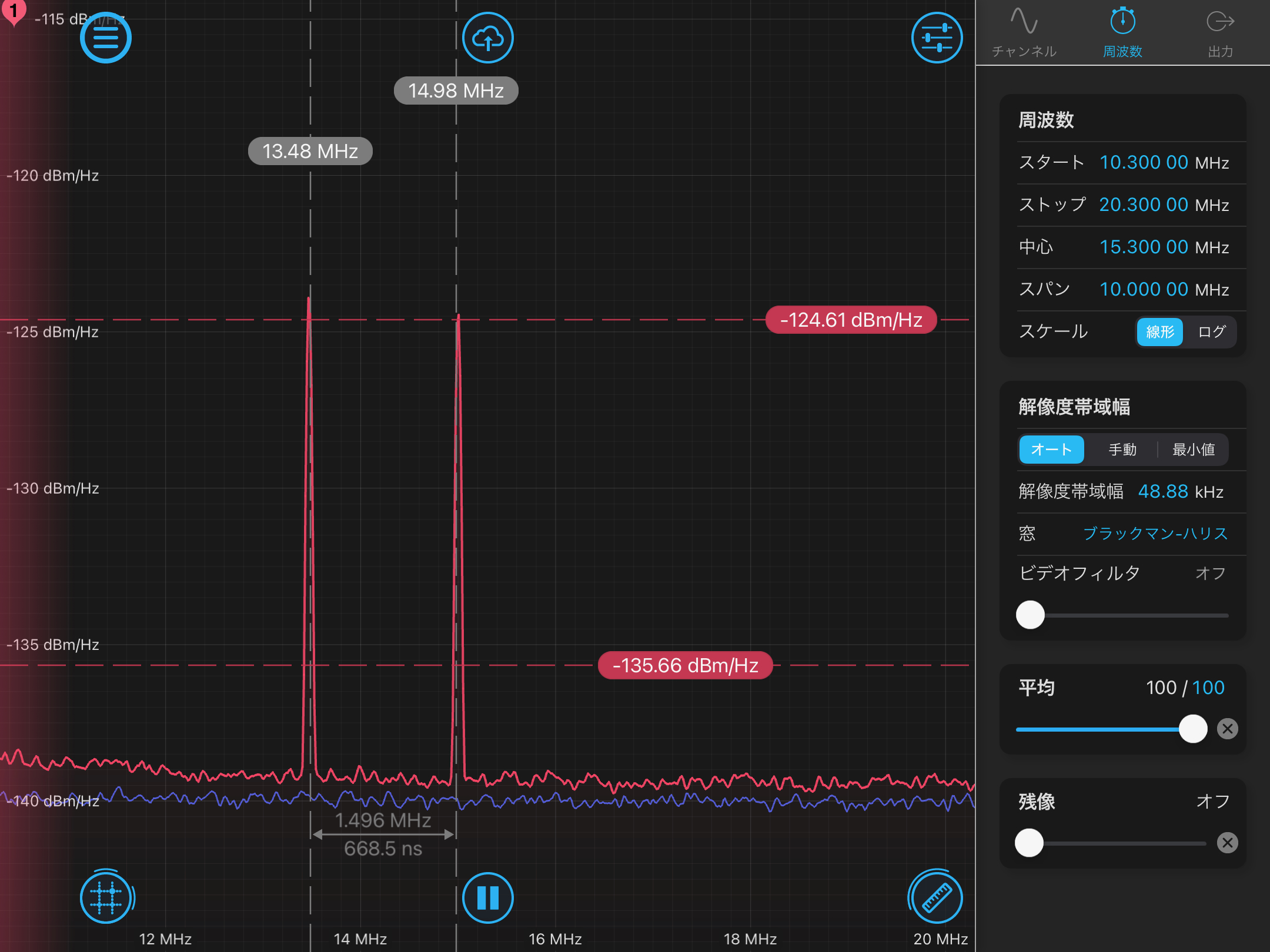
Next, we put mirrors after EOM1 to pick off the main beam and monitor RFAM with another RFPD. This time we didn't put any polarizer in front of this RFPD. That is, in theory we cannot observe any RFAM. In reality, we observed peaks at f_imc and 15 MHz (f_pmc, the modulation frequency for locking PMC) (Figure1). When we blocked the RFPD these peaks dissapeared. Therefore, these peaks came from the laser. We think the peak at f_pmc comes from RFAM induced by a fiber EOM.
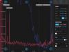
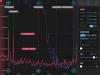
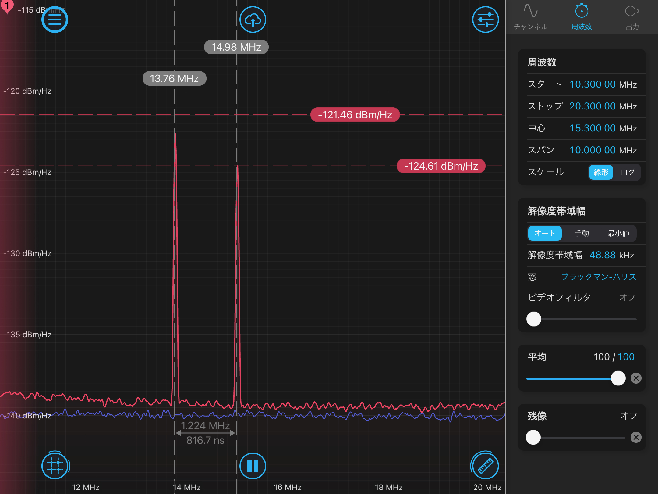
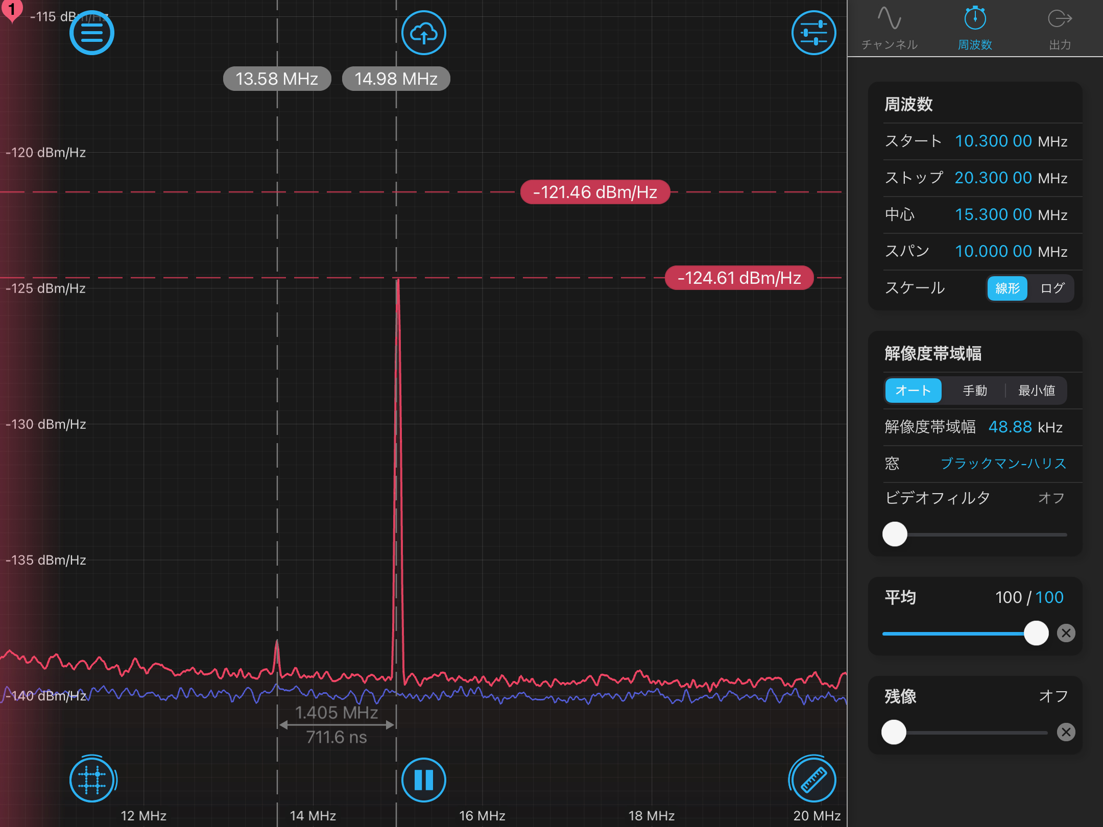
If we rotated the HWP in front of EOM1, the height of peak at f2 and f_imc changed but their behavior were different; for f2 the minimum peak height was achieved when the input polarization is around pure s-pol (Figure1) and sure p-pol (Figure2), but for f_imc the minimum value was achieved when the polarization is close to p-pol but a bit off (Figure3).
Changing the modlation frequency
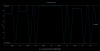
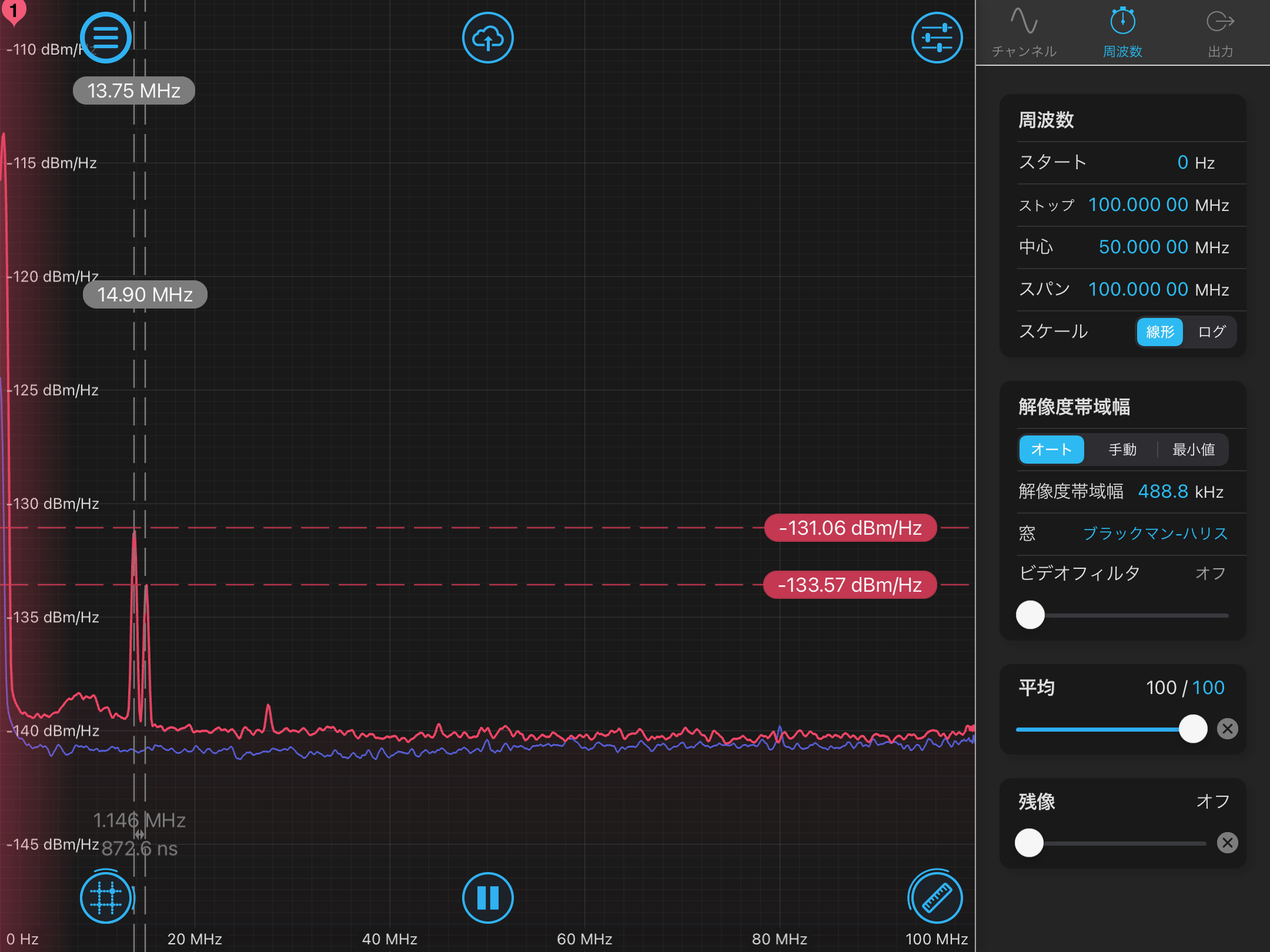
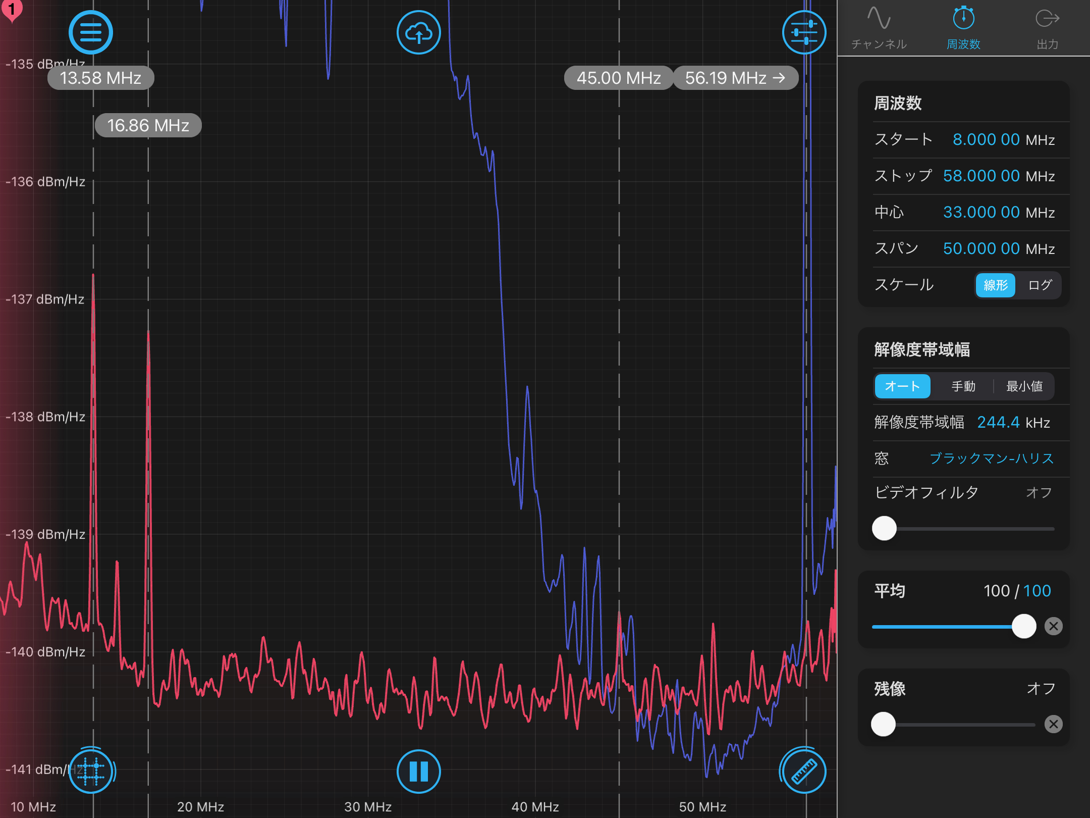
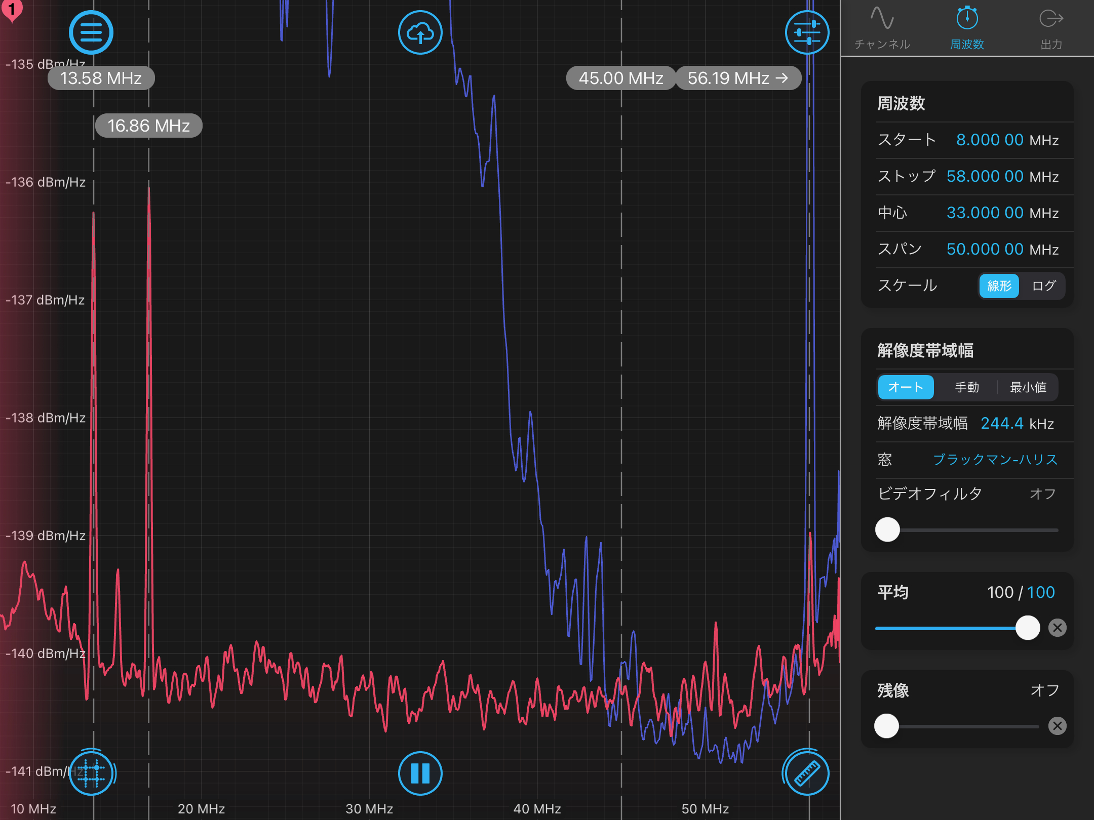
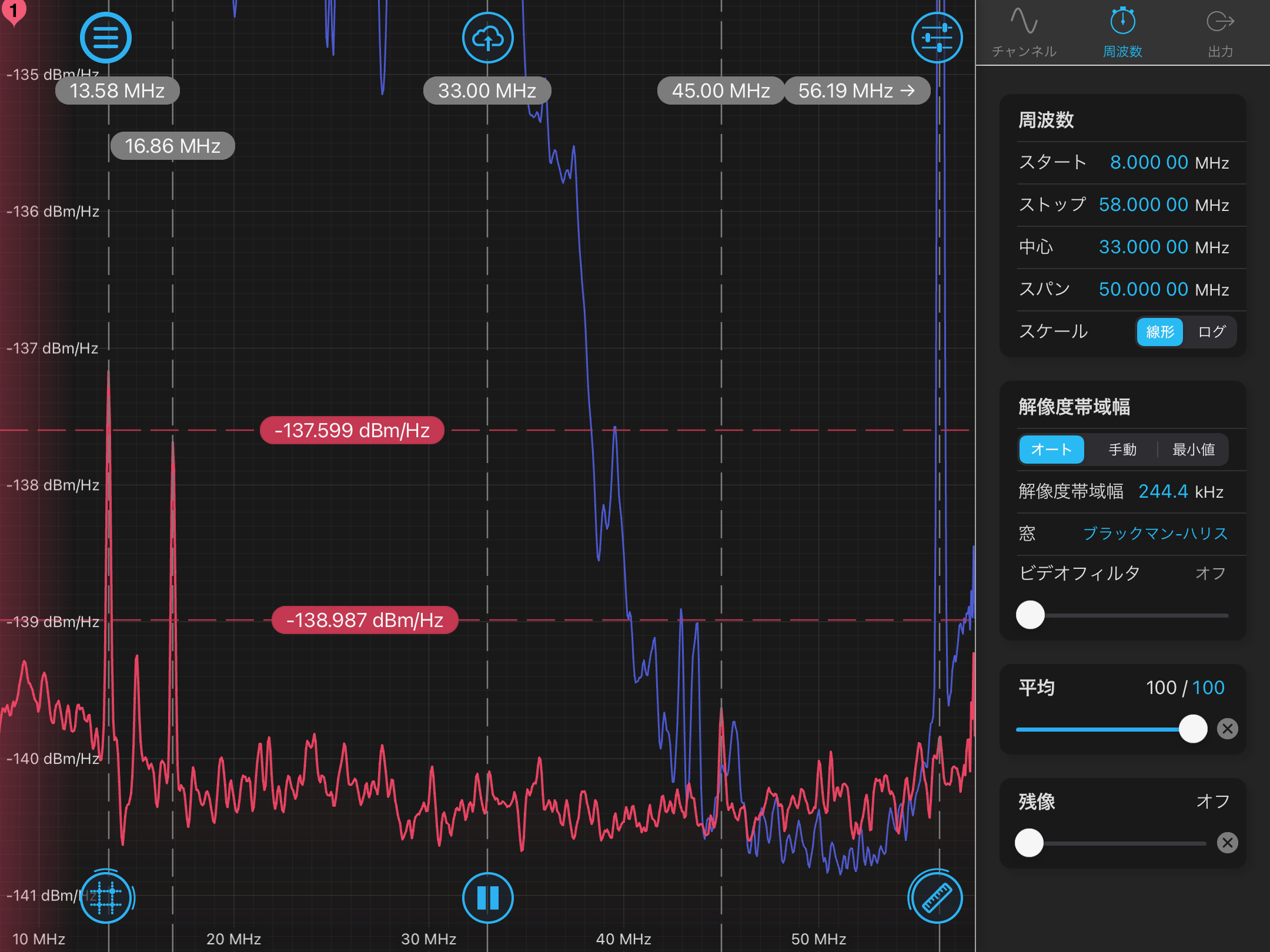
After going back to sure s-pol situation, we tried changing the modulation frequency of f_imc a little. Figure4 shows the RFAM spectrum of the original setting (f_imc = 13.77 MHz). If we set the modulation frequency to 13.57 MHz, the peak height was drastically reduced (Figure5). But the peak height was incredibly sensitive to the modulaiton frequency; if we set the frequency to 13.47 MHz (Figure6) and 13.67 MHz (Figure7) the peak height changed a lot, and even we changed the frequecy from 13.57 MHz by 1 kHz we saw some increase of the height. At that we kept f_imc at 13.57 MHz.
RF level change by human activity
While monitoring we noticed that when we came close to EOM1 the peak level at f_imc changed (higher) but after we went away it immediately decreased back to the previous level. We think it was hard to be explained by the change of the temperature of EOM1 because of the fast response, and we suspect the coupling of tilt of EOM1.
Polarization after EOM1
Next we tuned the polarization so that the height of f2 was minimized with the RFPD signal. After that, we put a QWP and a PBS in front of the RFPD and checked the reflection/transmission power roughly by two PDs. We confirmed that the output light was not sure s-pol because some part of light transmitted the PBS, and we were able to minimized it by rotating the QWP in front of the PBS. However, we are not sure from this measurement that the output light has some (relatively large) ellipticity or is a linear polarization which axis is different from the optical axis of the PBS.
Optimization of the polarization to EOMs with RFAM monitor
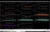
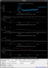
We finished the investigation about the output of EOM1, and removed a steering mirror which blocked the main beam path. We sent the laser to IMC, and tried to tune the input polarization again with monitoring the original RFAM monitor. Figure8 shows the RFAM spectrum tuned to sure s-pol, and by rotating the wave plates the peak at f2 was minimized but for f1 and f3 sidebands the value got higher (Figure9). Next we tuned the wave plates so that the peaks at f1 and f3 are minimized and gave up to optimize the polarizaiton for f2 (Figure10). With this tuning we left PSL room.
Ellipticity of the output of EOMs
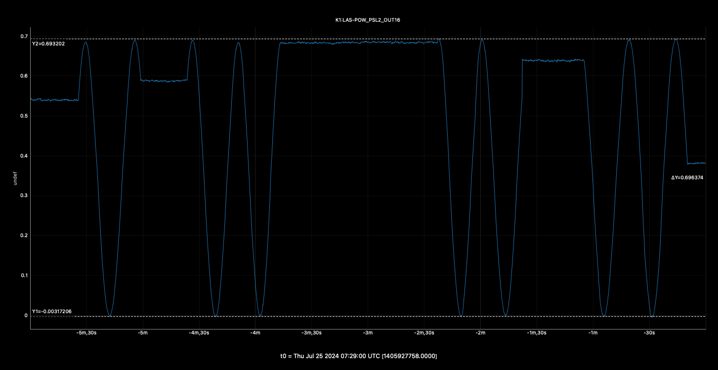
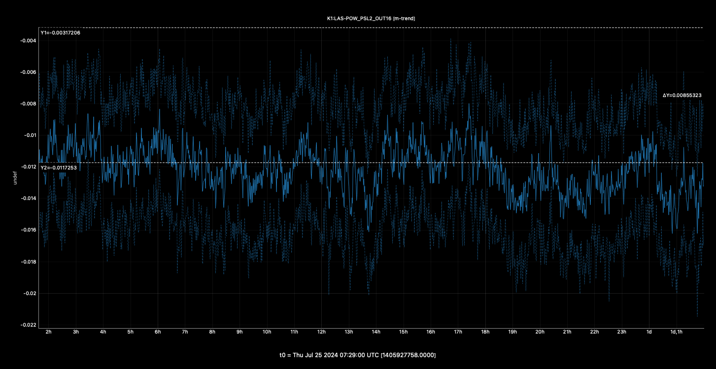
From the outside of PSL room we rotated the HWP before TFPs and monitored the change of the power which transmitted them (Figure11). Considering the offset value of the channel (Figure12), the estimated ellipticity is ~ 1.3e-2, which is pretty bad considering the extinction ratio of TFPs (I don't know the actual value, but usually it's above 1e4). This result implies that the polarization after EOM2 is elliptic with this level and further tuning of the polarization is necessary.
Offset value of the demodulated signals
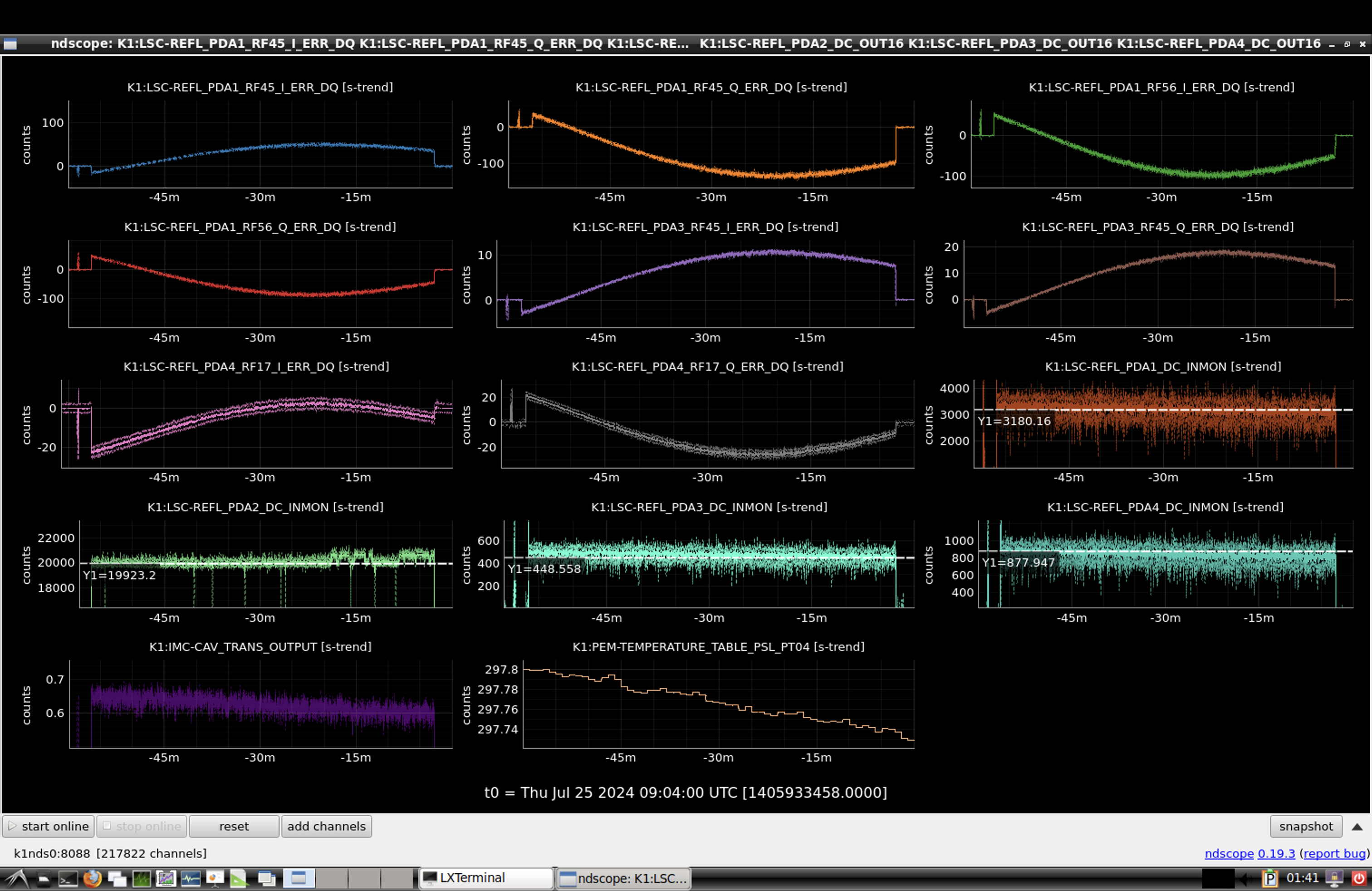
After measuring the ellipticity we locked IMC,aligned PRM and monitored the offset value of the demodulated signals of REFL RFPDs. The results are shown in Figure12. the offset values were suppressed by ~ 1o times from the previous measurement. Note that at that time DC power of each PD was about 2.5 times smaller than the previous measurement. Therefore, the actual suppression ratio is roughly 4. Anyway, we concluded that our tuning worked well this time.
Next
- Put wave plates between EOM1 and EOM2 to adjust the polarization injected to EOM2
- Prepare motors to tune the angle of the wave plates more precisely than manual adjustment
- Increase laser power and see the difference from the current (low power) situation


