Reports 1-1 of 1 Clear search Modify search
VIS (EY)
ryutaro.takahashi - 17:07 Thursday 25 July 2024 (30572) Print this report
Test of IP control with accelerometers

[Washimi, Ushiba, Takahashi]

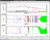
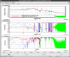
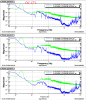
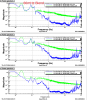
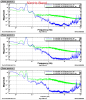
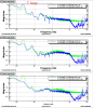
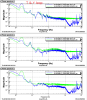
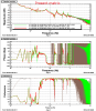
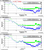
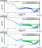
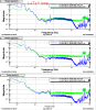
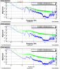
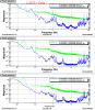
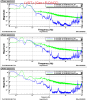
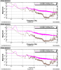
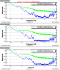
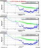
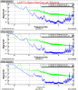
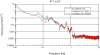
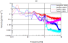
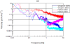
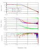
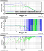
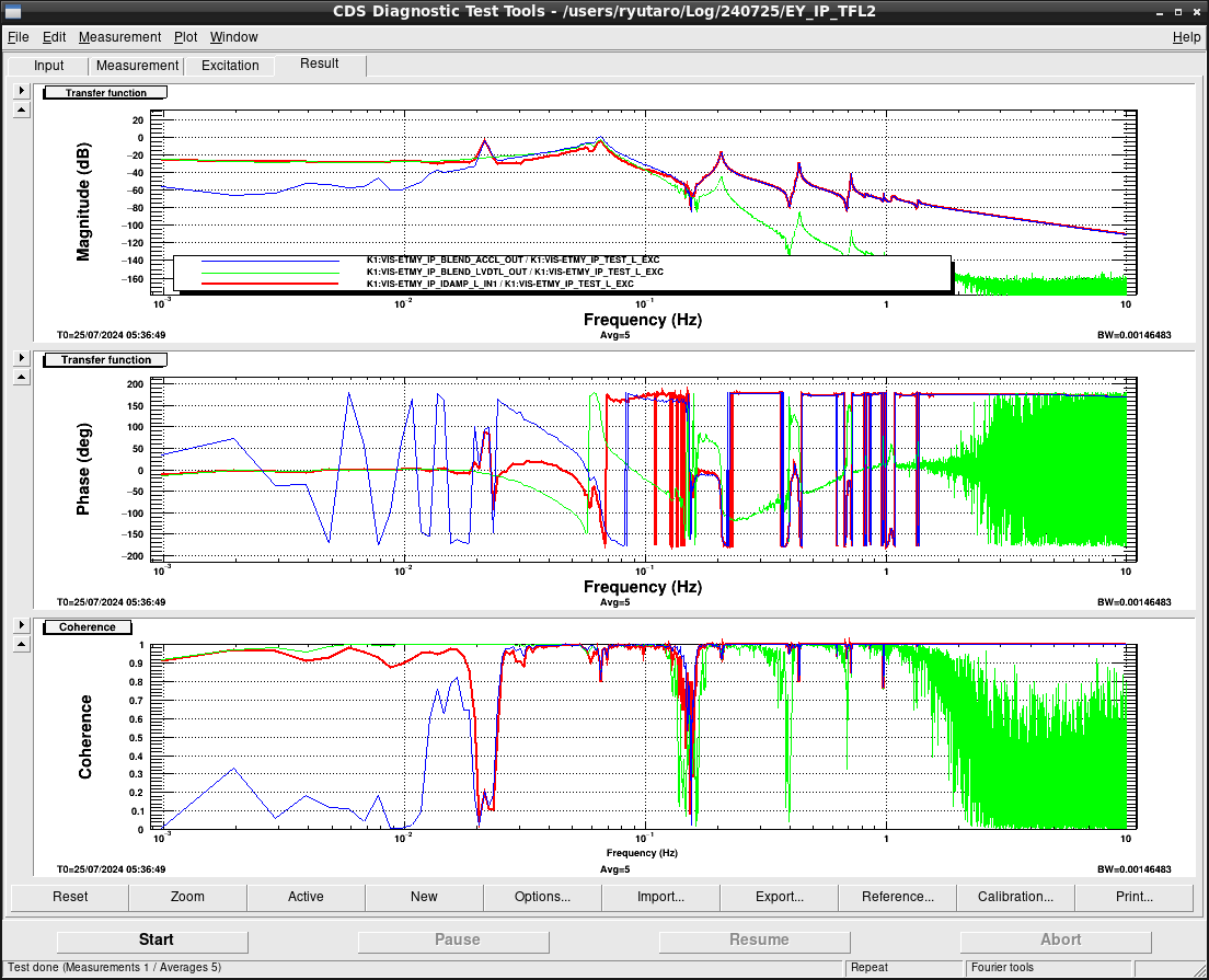
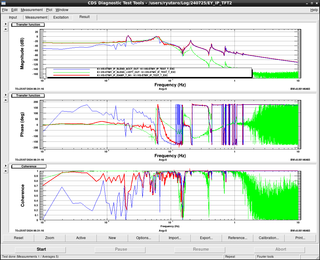
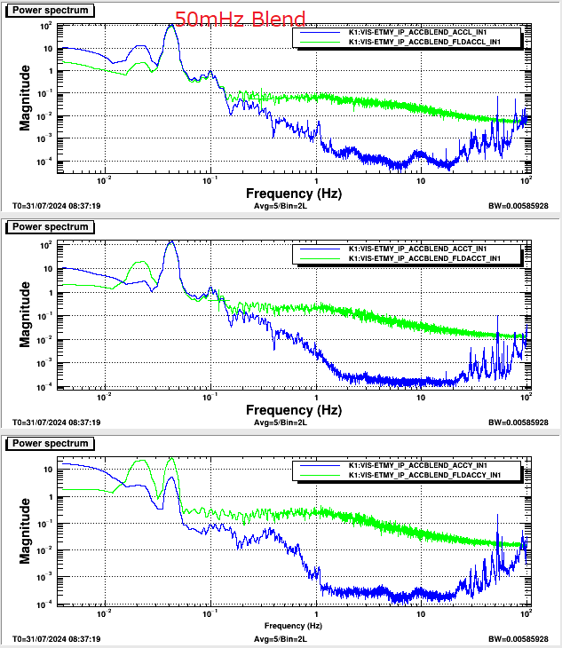
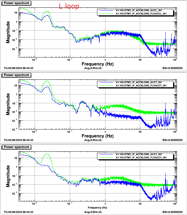
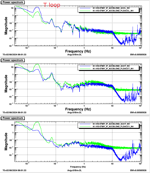
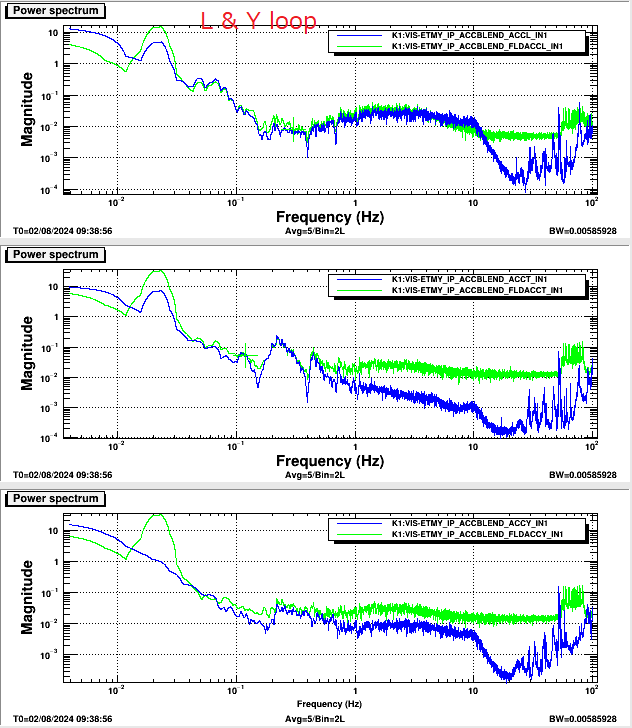
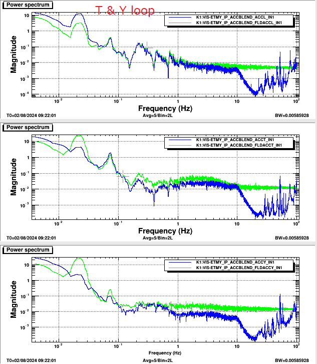
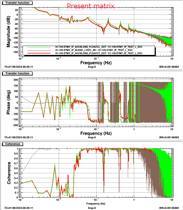
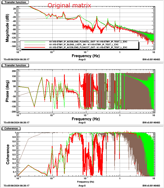
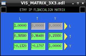
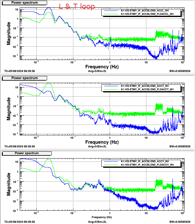
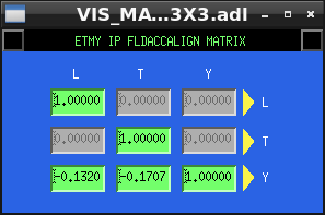
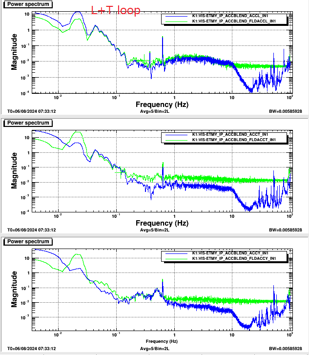
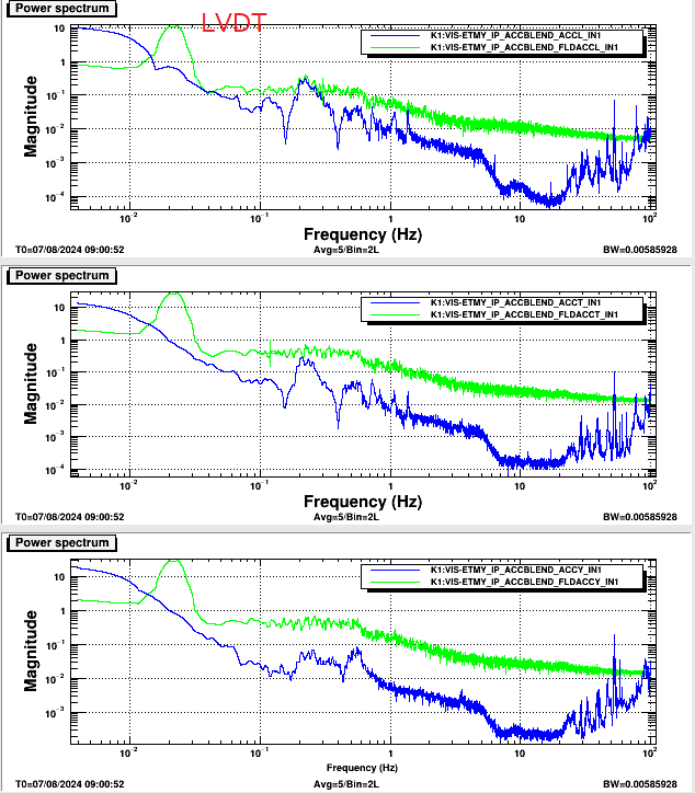
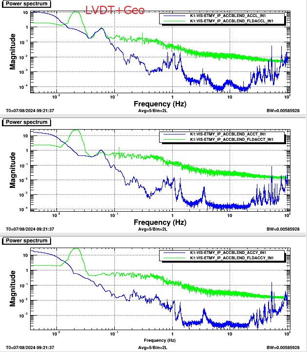
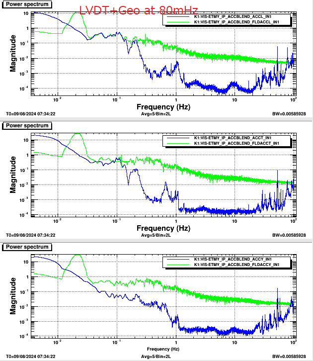
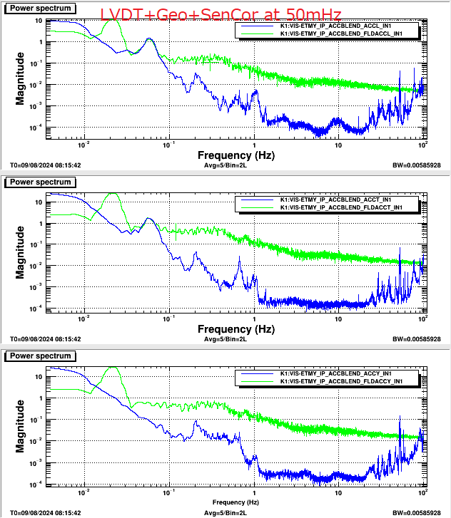
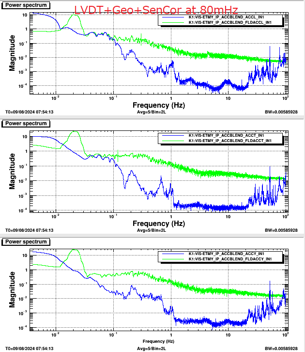
We measured the transfer functions of the IP from the virtual actuator (L, T) to each virtual sensor and blended sensors. The inertial sensors and the LVDTs were blended at 50mHz. The blended TF of L has a small dip around 60mHz. The phase correction for the inertial sensors should be adjusted.

Images attached to this report
Comments to this report:
ryutaro.takahashi - 18:48 Wednesday 31 July 2024 (30655) Print this report

I measured the IP spectra in the following cases;

  1. Control using only the LVDTs without the inertial sensors.
  2. Control using the LVDTs and the inertial sensors blended at 80mHz.
  3. Control using the LVDTs and the inertial sensors blended at 50mHz.

I have not adjusted the phase correction filters for the inertial sensors yet. In the case of the 50mHz blending, 40mHz oscillation was glowing. The noise of the FLDACCs looks large.

Images attached to this comment
ryutaro.takahashi - 6:43 Friday 02 August 2024 (30684) Print this report

I adjusted the phase correction filters for the inertial sensors and tried the control using the 50mHz blending. 40mHz oscillation was not improved. So I measured the L and T TFs to each sensor (LVDT, ACC(Geophone), and FLDACC) without any phase corrections to confirm the phase deviations.

Images attached to this comment
ryutaro.takahashi - 11:44 Sunday 04 August 2024 (30707) Print this report

I remade the phase correction filters as FM4 'Cor' in ACCBLEND for the inertial sensors and tried the control using the 50mHz blending. Though the control loop for L only, T only, L&Y, and T&Y could work without 40mHz oscillation, the L&T loop increased the oscillation. The spurious pass due to the coupling of L and T seems to make the oscillation.

Images attached to this comment
ryutaro.takahashi - 21:50 Monday 05 August 2024 (30719) Print this report

I checked the TF from the L actuator to the L or T FLDACC. The coupling L to T was large (86% at 50mHz). I found the present matrix had a large non-diagonalized component (0.3658) for L to T. I remeasured the TF using the original (identity) matrix. The coupling L to T was degreased (50% at 50mHz). I tried to control the IP using both L&T loops with the original matrix. It could work without 40mHz oscillation.

Images attached to this comment
ryutaro.takahashi - 18:25 Tuesday 06 August 2024 (30734) Print this report

I tried to control the IP using the L+T+Y loops in the 50mHz blending. When I added the Y loop to the L+T loops, 40mHz oscillation increased. I modified the matrix for the FLDACC as shown in Fig.1. The oscillation was settled, but the noise level of the inertial sensors was larger than the spectra measured yesterday.

Images attached to this comment
ryutaro.takahashi - 21:30 Wednesday 07 August 2024 (30767) Print this report

I compared the IP spectra in the following cases.

  1. Control using the LVDTs only.
  2. Control using the LVDTs and the geophones blended at 50mHz (110mHz for Yaw).
  3. Control using the LVDTs and the inertial sensors (Geophones and FLDACCs blended at 100mHz) blended at 50mHz (110mHz for Yaw).
Images attached to this comment
ryutaro.takahashi - 11:25 Thursday 08 August 2024 (30776) Print this report

I checked the performance of the FLDACCs. The plot shows the spectra of the IP in the case of the control using the LVDT only. The noise floor of the H2 FLDACC was larger than the H1/H3 FLDACCs by several times. According to the klog in the tuning of the folded pendulums, the TF of the H2 FLDACC (made of Al) showed a hysteresis damping due to friction. It might be the reason for the bad performance of the H2 FLDACC.

Images attached to this comment
ryutaro.takahashi - 17:57 Friday 09 August 2024 (30805) Print this report

I compared the IP spectra in the following cases.

  1. Control using the LVDTs and the geophones blended at 50mHz (110mHz for Yaw).
  2. Control using the LVDTs and the geophones blended at 80mHz (110mHz for Yaw).
  3. Control using the LVDTs and the geophones blended at 50mHz (110mHz for Yaw) with the sensor correction.
  4. Control using the LVDTs and the geophones blended at 80mHz (110mHz for Yaw) with the sensor correction.

In these cases, the performance of the #1 case was the highest. There is plenty of room for improvement in the present sensor correction.

Images attached to this comment
ryutaro.takahashi - 15:18 Saturday 17 August 2024 (30858) Print this report

I compared the IP spectra measured by the geophones in the following cases. The IP was controlled with the LVDTs and the geophones blended at 50mHz (110mHz for Yaw).

  1. Without sensor correction.
  2. With sensor correction using the present filter "AC" (80mHz resonant high pass).
  3. With sensor correction using the modified filter "AC2" (1mHz high pass).

The filter "AC2" reduced the noise due to the LVDT around 100mHz.

Images attached to this comment
ryutaro.takahashi - 14:12 Tuesday 20 August 2024 (30870) Print this report

I modified the Gurdian for Type-A in EY. The inertial damping of IP is applied in the LOCK_ACQUISITION mode. The LVDT and geophone signals are blended at 50mHz. The sensor correction using the "AC2" filter is also applied.

Search Help
×

Warning

×