Takano, Yamamoto
Abstract
We measured the trransfer function of the actuators. We found that each transfer function is close to ech other between 0.6 Hz and 3 Hz, the sum of them are complicated and sometimes results in unstable shape. We added a damping filter temporarily, but fine tuning of the filters are necessary for better control in future.
Detail
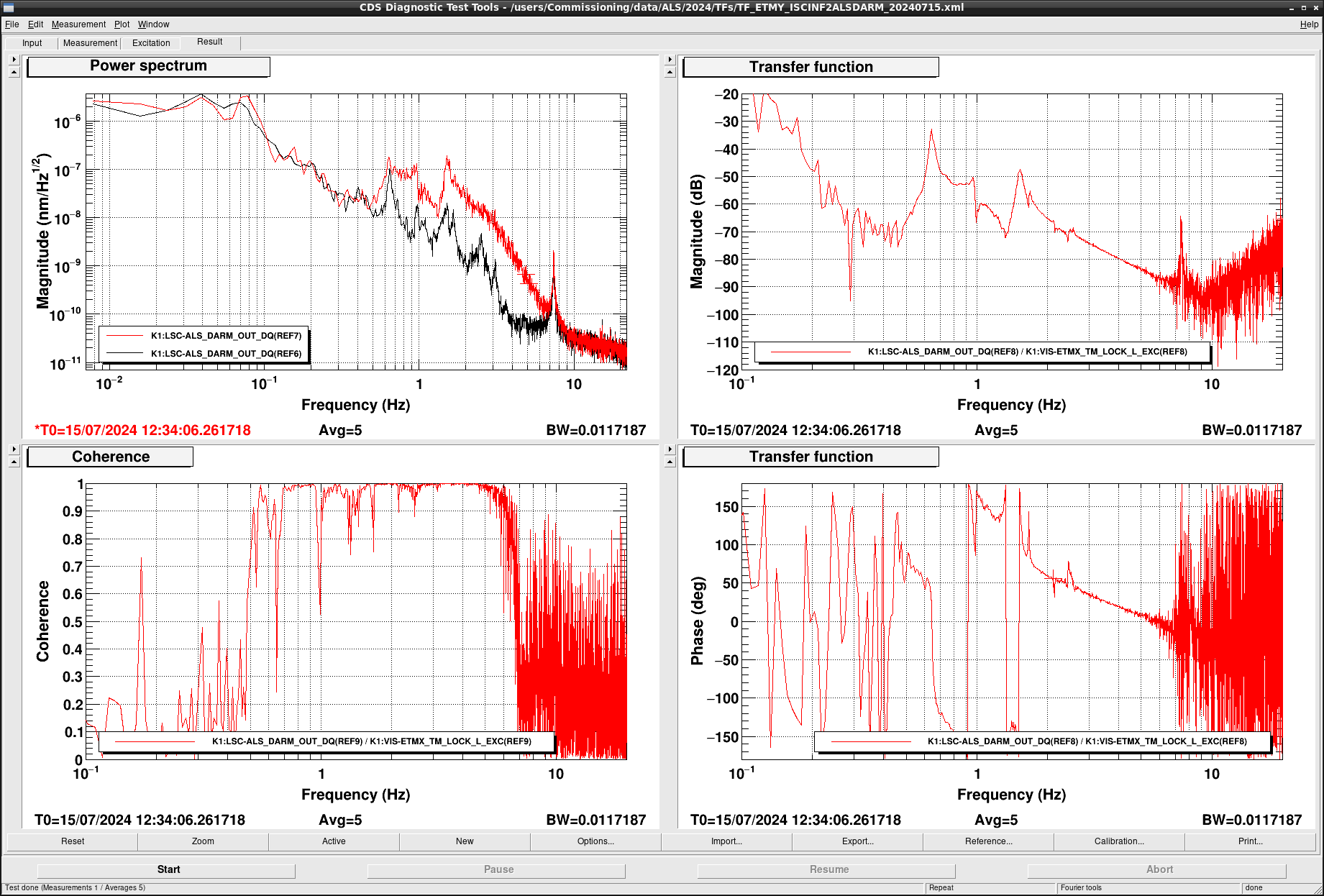
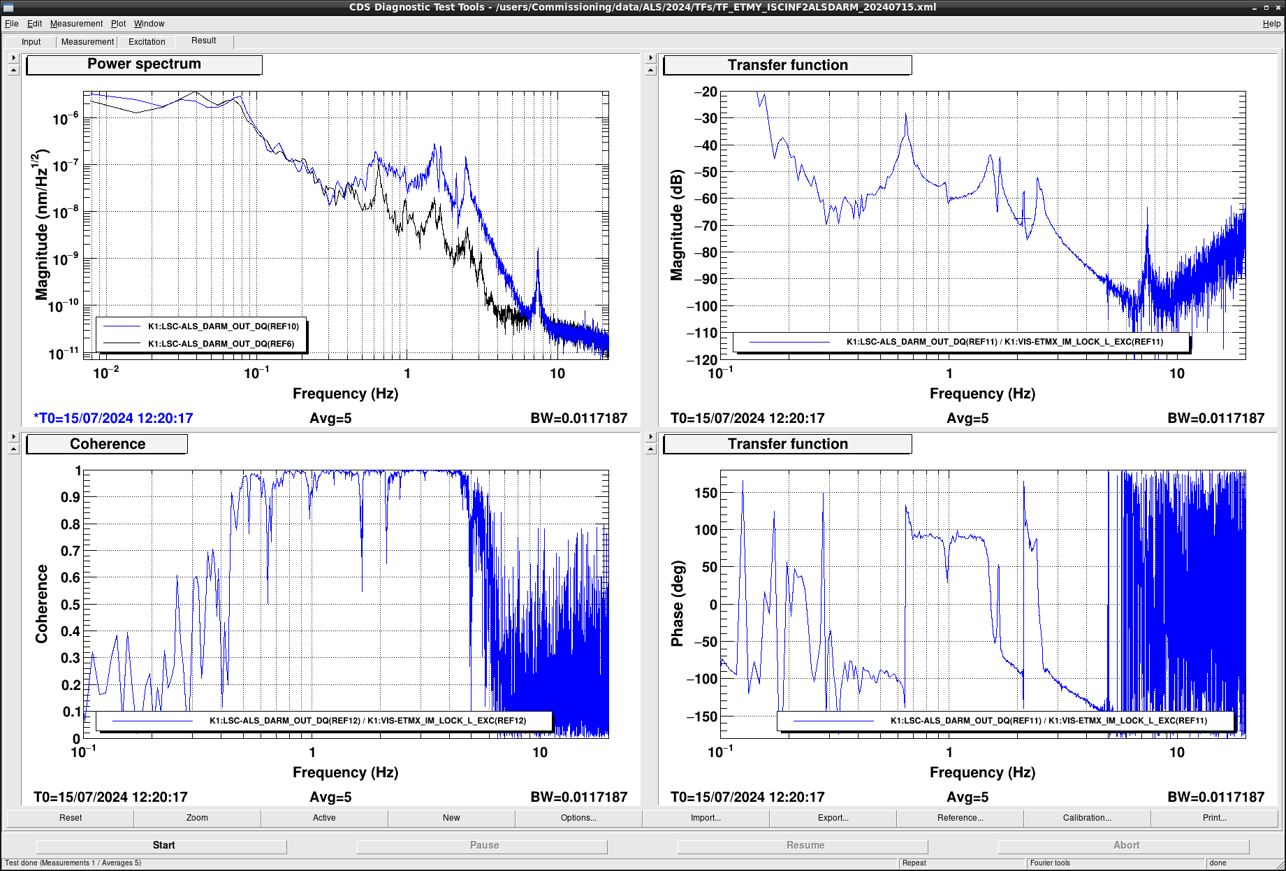
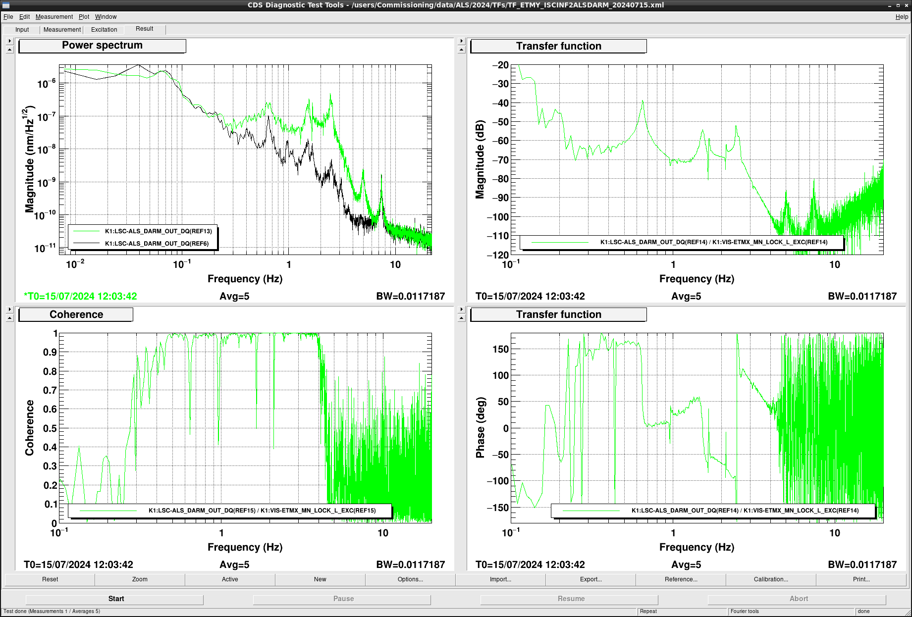
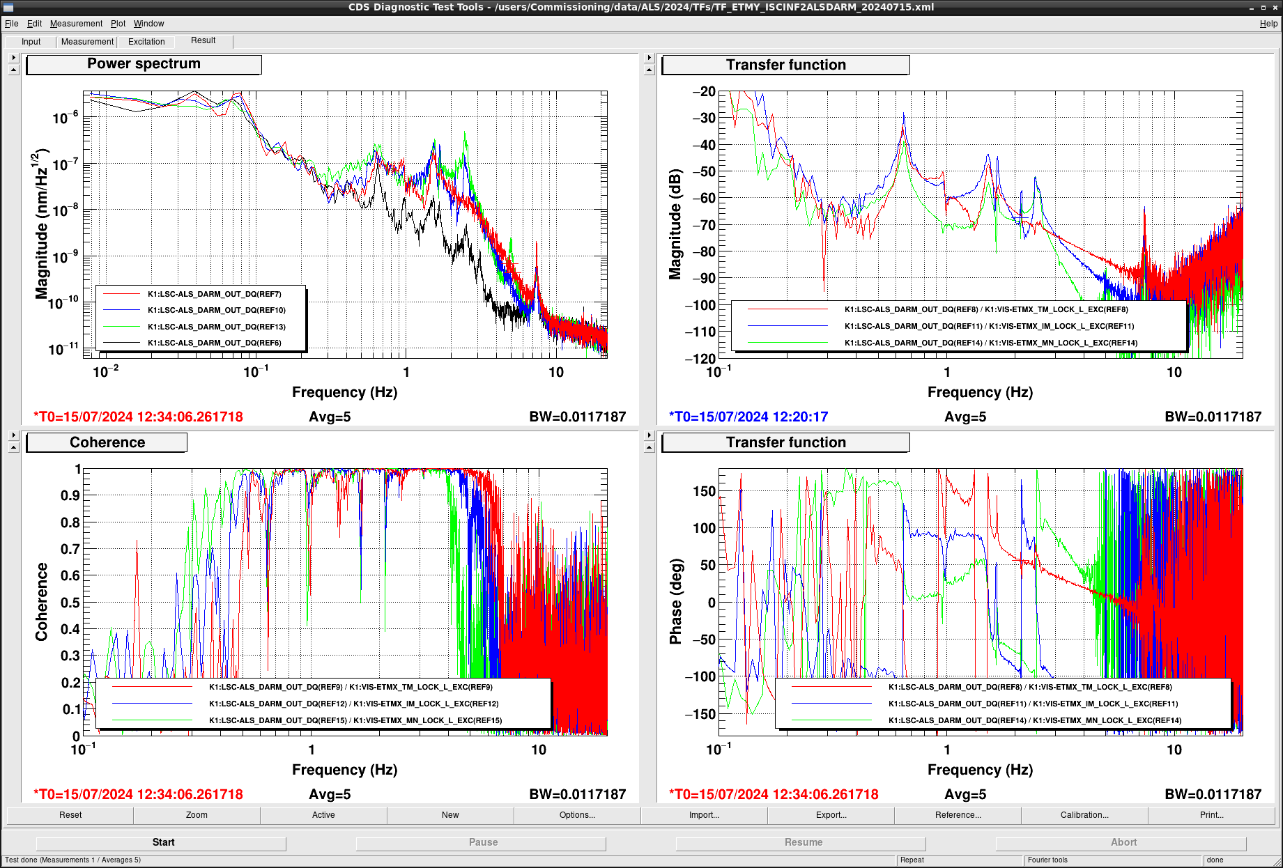
To investigate the reason of oscillation at 2.1 Hz (Yokozawa-san reported the frequency of oscillation was 2.7 Hz, but actually it was 2.1 Hz), we tried measuring the transfer function of each actuator on ETMX with ALS CARM locked. We injected excitation at K1:VIS-ETMX_{TM,IM,MN}_LOCK_EXC and measured the transfer function from the injection signal to K1:LSC-ALS_DARM_OUT. The injection measurements were done one by one. Figure1 - Figure3 show the measured transfer function from TM, IM, and MN_LOCK_EXC to ALS_DARM. Figure4 shows these TFs on the same plot. From these plot, we can see that the magnitude of the transfer functions are close to each other and hard to tell whether the sum of them are stable or not.
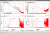
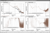
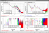
Next we measured the transfer function from K1:VIS-ETMX_TM_ISCINF_EXC to K1:LSC-ALS_DARM_OUT. Figure5 shows the transfer function, and Figure6 shows the comparison with the transfer function from each suspension stage. From this measurement, we noticed that there is a sharpe phase rotation and a sudden gain jump at 2.1 Hz which seems the resonant mode related to IM. We suspected that this structure caused the oscillation during ALS DARM lock.
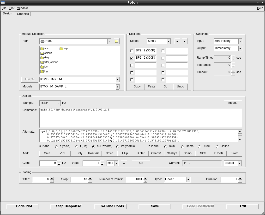
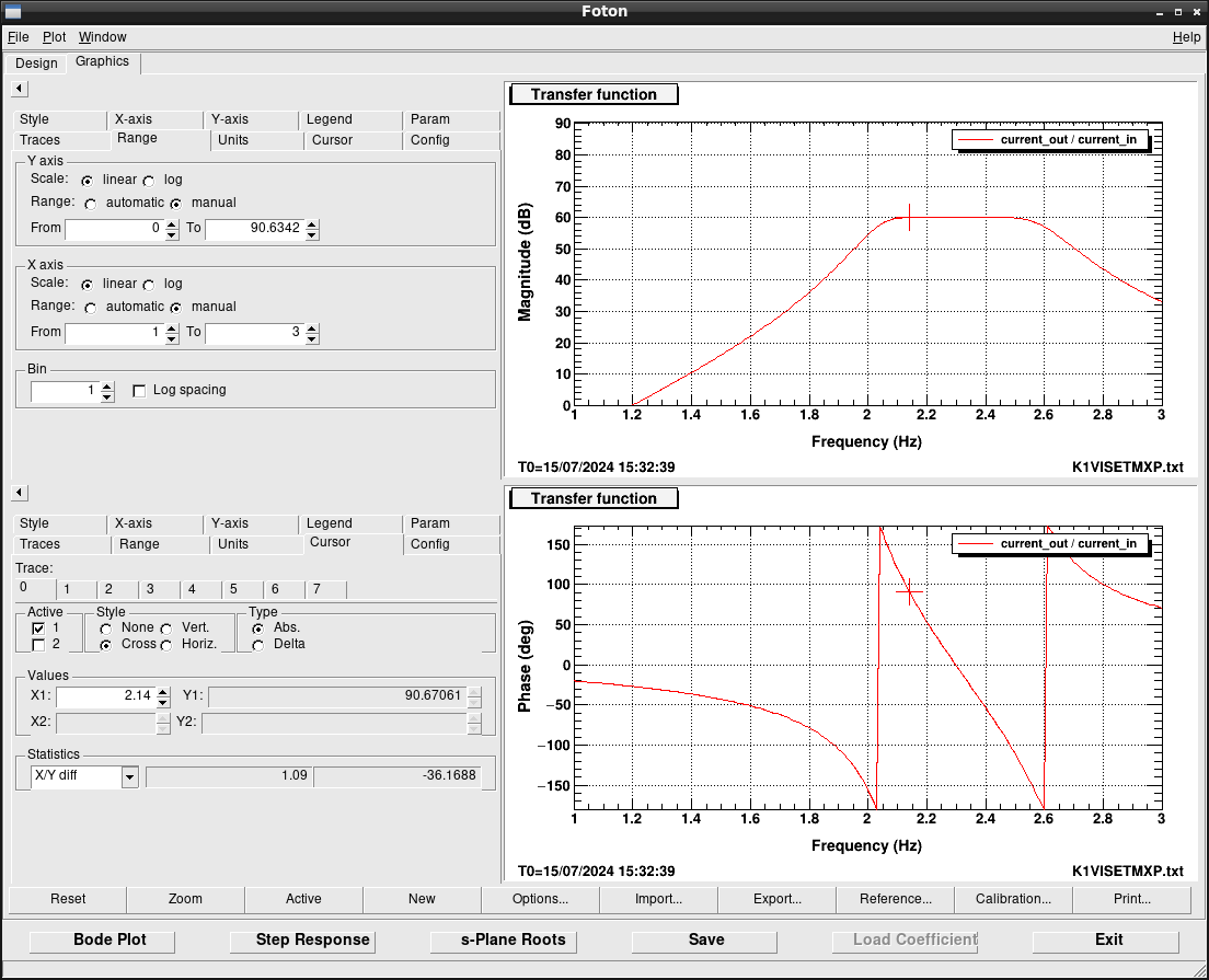
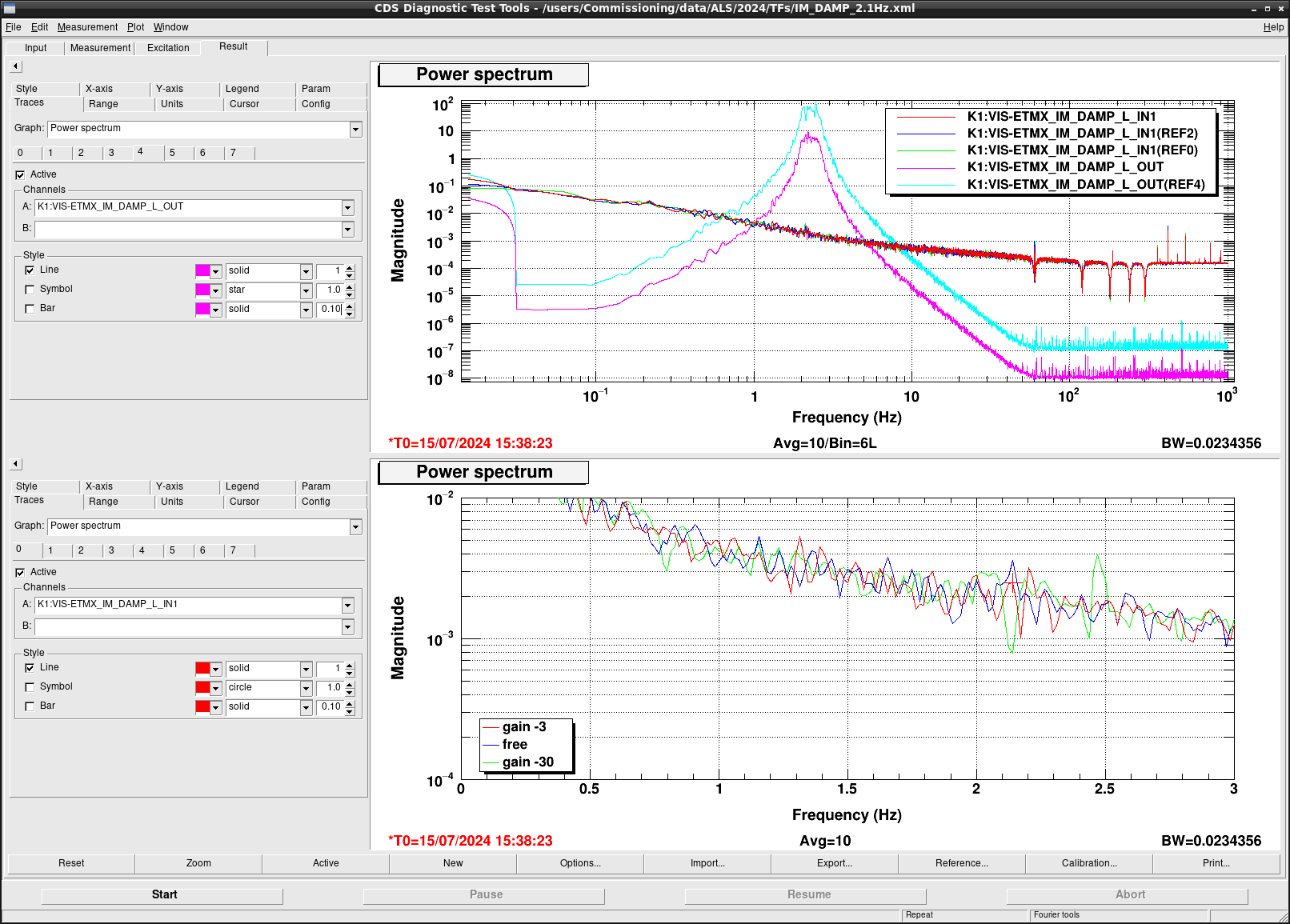
To damp the resonant peak, we temporarily implemented a damping loop with the photosensor signal if ETMX IM L. We designed a damping filter and added it in K1:VIS-ETMX_IM_DAMP_L as shown if Figure7 and Figure8. Figure9 shows the spectra of K1:VIS-ETMX_IM_DAMP_L_IN1 with various conditions. The blue curve is the spectrum without control, and the red (green) curve show the spectra when the control was closed with gain -30 (-3). Without any actuation, the photosensor barely see the peak at 2.14 Hz with S/N ~ 2. In thhe case with gain of -30, we can see an excess noise at 2.5 Hz, which is another resonant mode. This is due to a finite gain of the damping filter at 2.5 Hz. We tried to make the bandwidth of the filter narrrow, but finally gave up. Instead, we decreased the gain to -3 so that the filter does not excite the 2.5 Hz oscillation.
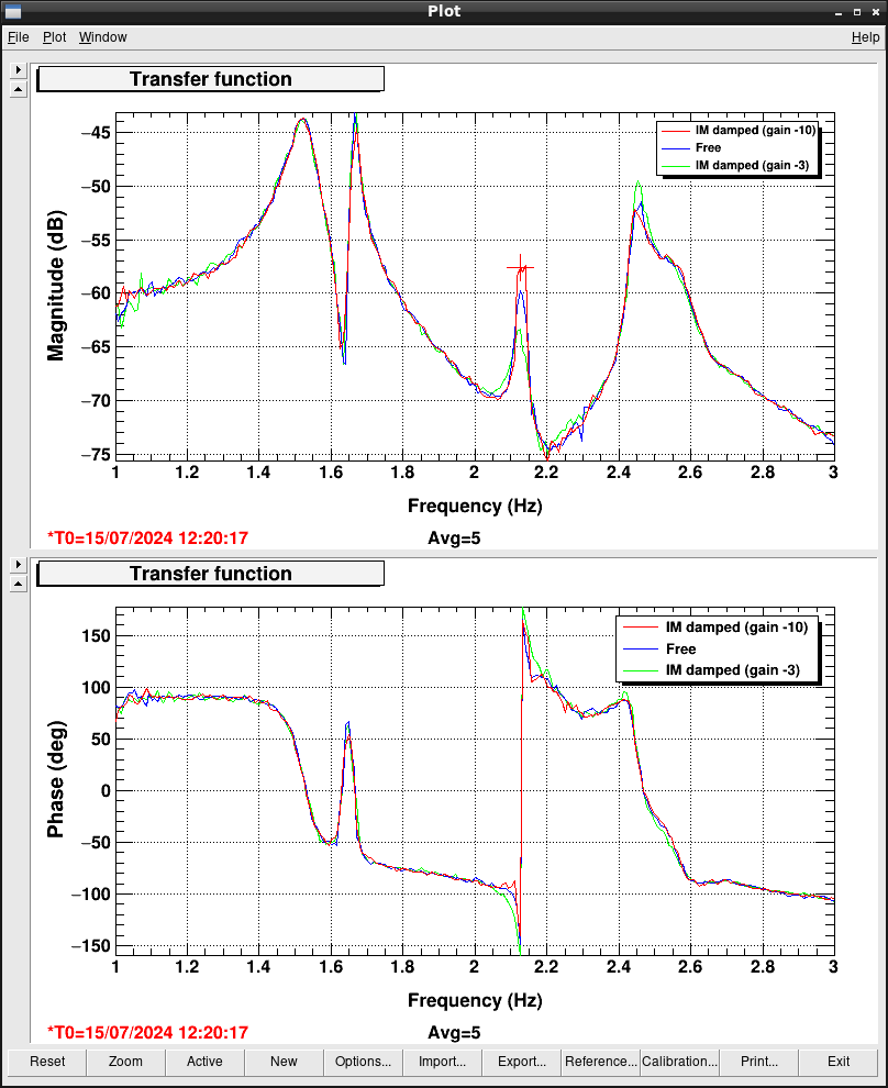
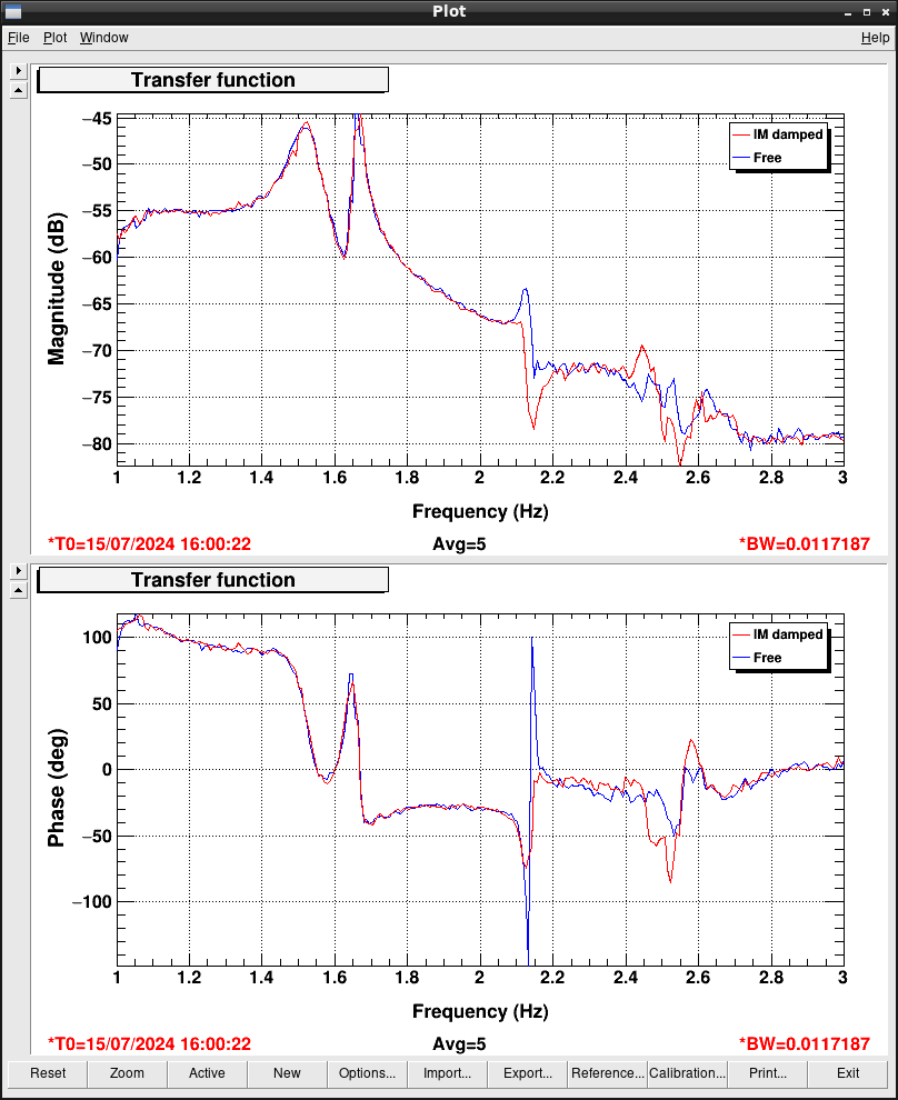
With this dammping filter, we measured the transfer function from K1:VIS-ETMX_IM_LOCK_EXC to K1:LSC-ALS_DARM_OUT as shown Figure 10. After some trials and errors, finally we set the filter gain as -10. now we can see that the sharp peak at 2.1 Hz is somehow damped, at the expense of higher gain at 2.5 Hz. Next we measured the transfer function from K1:VIS-ETMX_TM_ISCINF_EXC to K1:LSC-ALS_DARM_OUT. The result is shown in Figure11. With the damping control, the phase rotation is much damped and now the control loop with the hierarchical actuators seems stable.
Finally, we tried locking ALS DARM loop and succeeded as reported here.
Note
We don't think this damping filter is permanent, because when designing the filter we didn't care the relative gain and phase to each suspension stage and noise performance. In the suspension commissioning we should consider this filter design and the hierarchical structure as well.


