Reports 1-1 of 1 Clear search Modify search
VIS (OMM)
tatsuki.washimi - 12:58 Wednesday 10 July 2024 (30334) Print this report
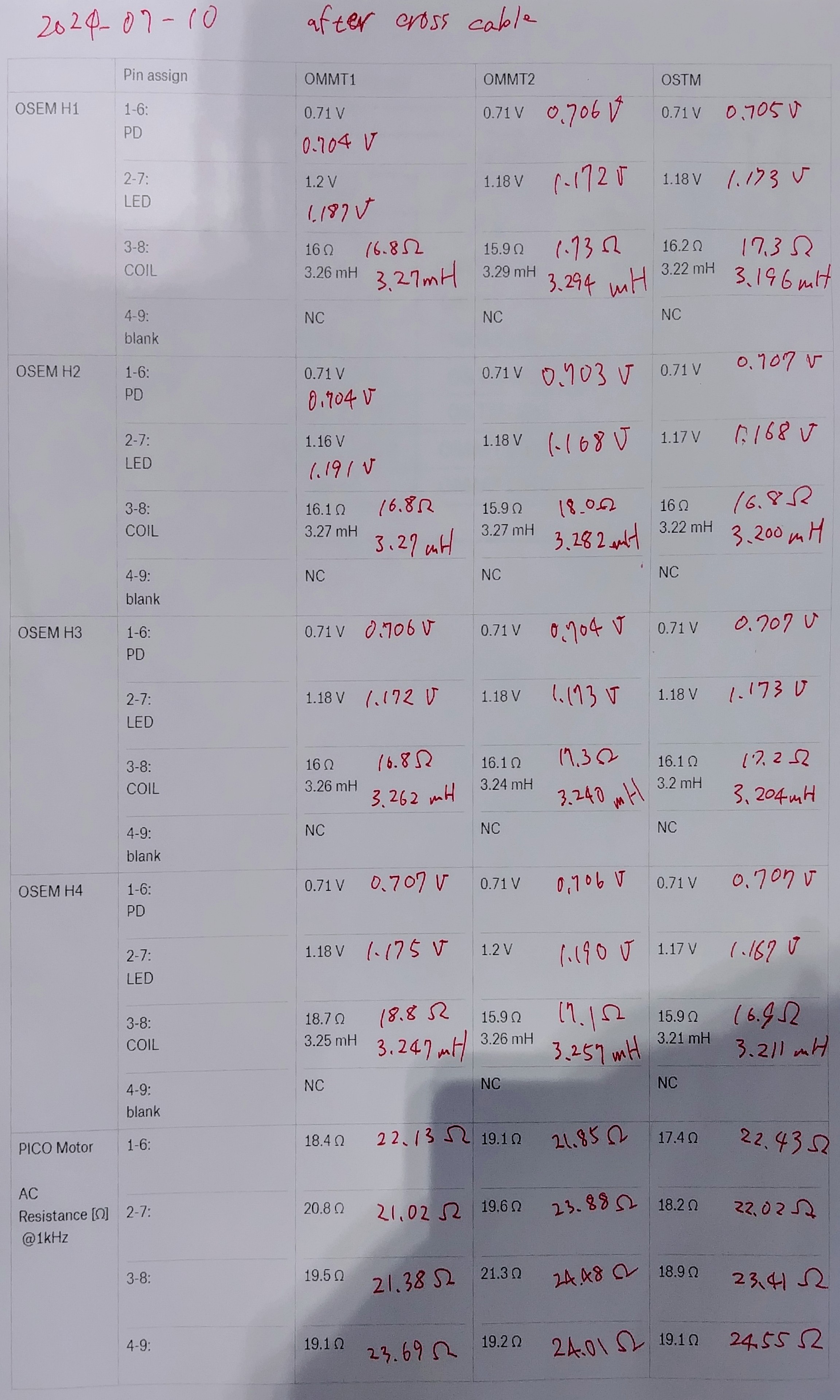
Resistance etc. measurements for the OMMT1,2 and OSTM

I measured the resistance, inductance, and voltage-dropping of the OMMT1,2 and OSTM suspensions, after the cross-cables.


Pin assign

OMMT1

OMMT2

OSTM

OSEM H1

1-6:  PD

0.704 V

0.706 V

0.705 V

2-7: LED

1.187 V

1.172 V

1.173 V

3-8: COIL

16.8 Ω
3.27 mH

1.73 Ω
3.294 mH

17.3 Ω
3.196 mH

4-9: blank

- - -

OSEM H2

1-6:  PD

0.704 V

0.703 V

0.707 V

2-7: LED

1.191 V

1.168 V

1.168 V

3-8: COIL

16.8 Ω
3.27 mH

18.0 Ω
3.282 mH

16.8 Ω
3.200 mH

4-9: blank

- - -

OSEM H3

1-6:  PD

0.706 V

0.704 V

0.707 V

2-7: LED

1.172 V

1.173 V

1.173 V

3-8: COIL

16.8 Ω
3.262 mH

17.3 Ω
3.240 mH

17.2 Ω
3.204 mH

4-9: blank

- - -

OSEM H4

1-6:  PD

 0.707 V

0.706 V

0.707 V

2-7: LED

1.175 V

1.190 V

1.167 V

3-8: COIL

18.8 Ω
3.247 mH

17.1 Ω
3.257 mH

16.9 Ω
3.211 mH

4-9: blank

- - -

PICO Motor@1kHz

1-6:  

22.13 Ω

21.85 Ω

22.43 Ω

2-7: 

21.02 Ω

23.88 Ω

22.02 Ω

3-8: 

21.38 Ω

24.48 Ω

23.41 Ω

4-9: 

23.69 Ω

24.01 Ω

24.55 Ω

Images attached to this report
Comments to this report:
tatsuki.washimi - 16:43 Wednesday 10 July 2024 (30336) Print this report

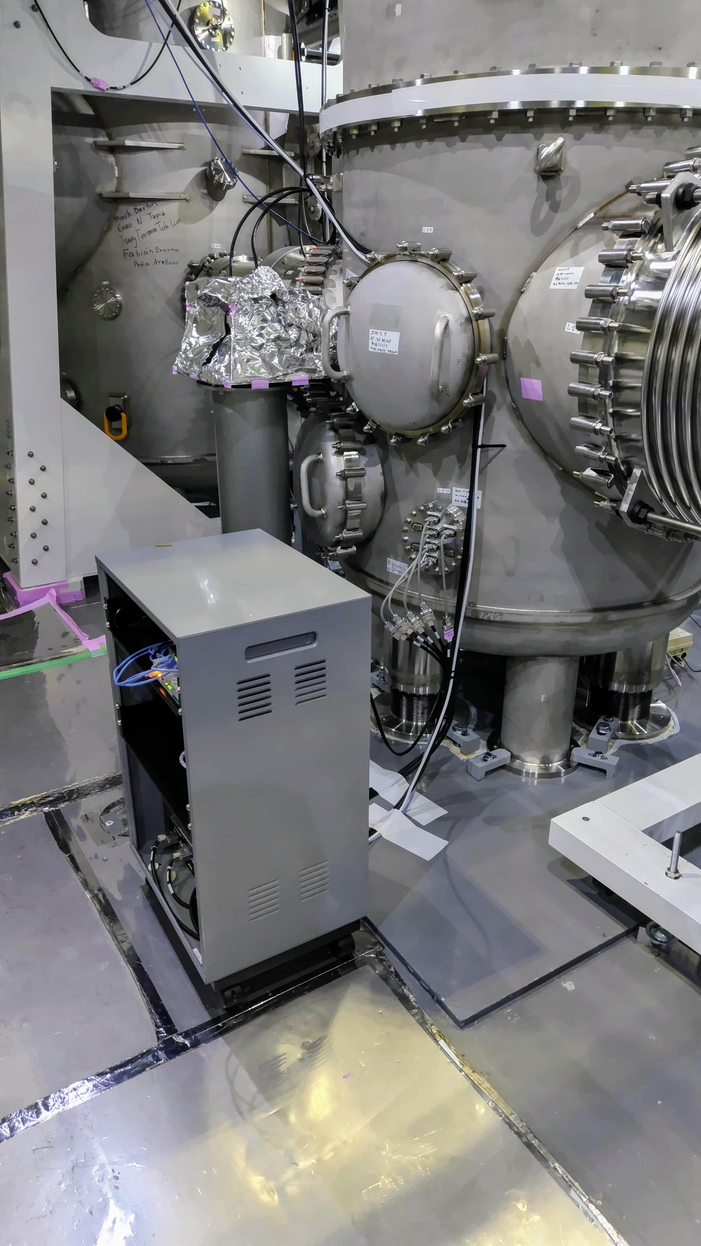
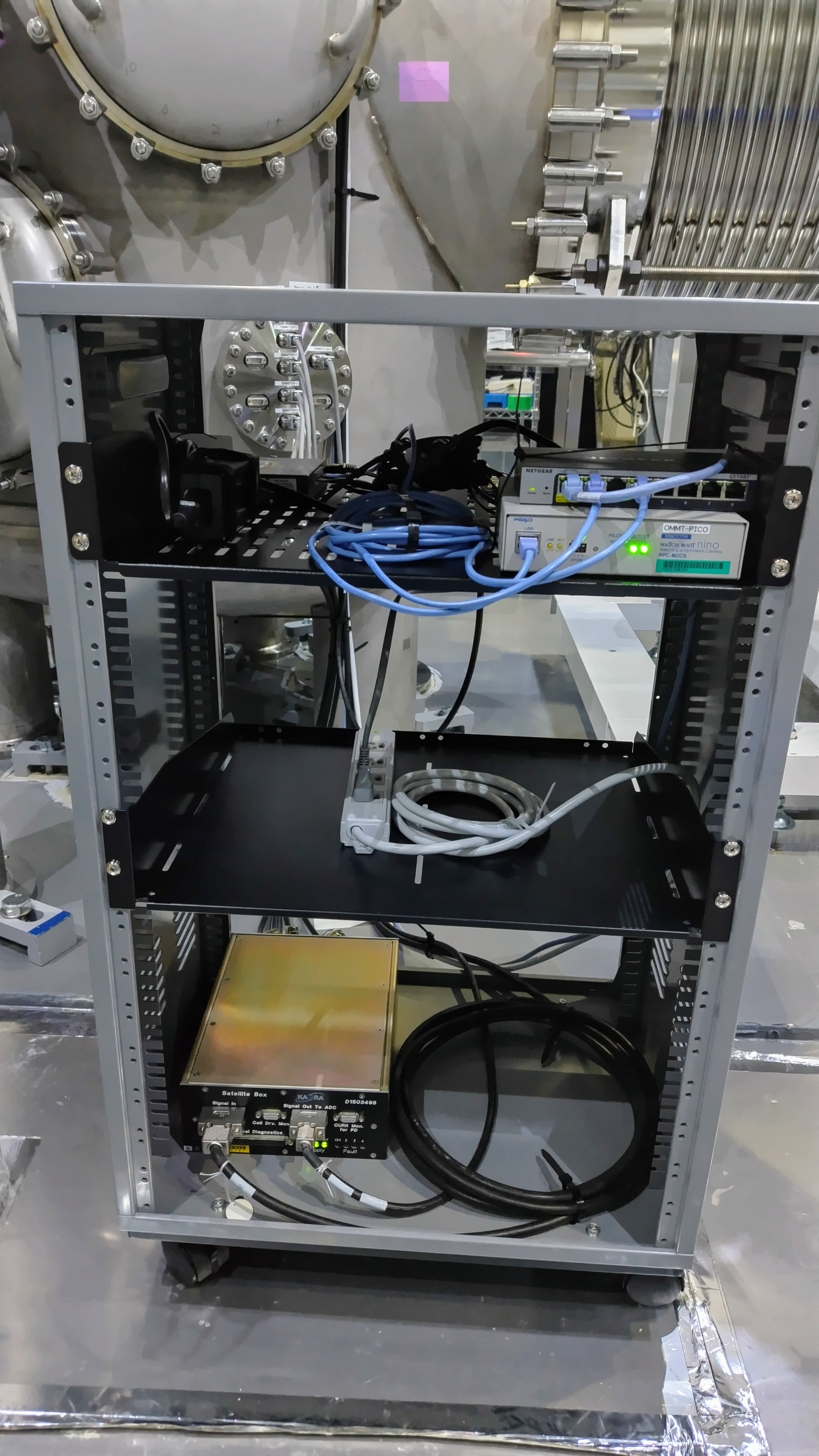
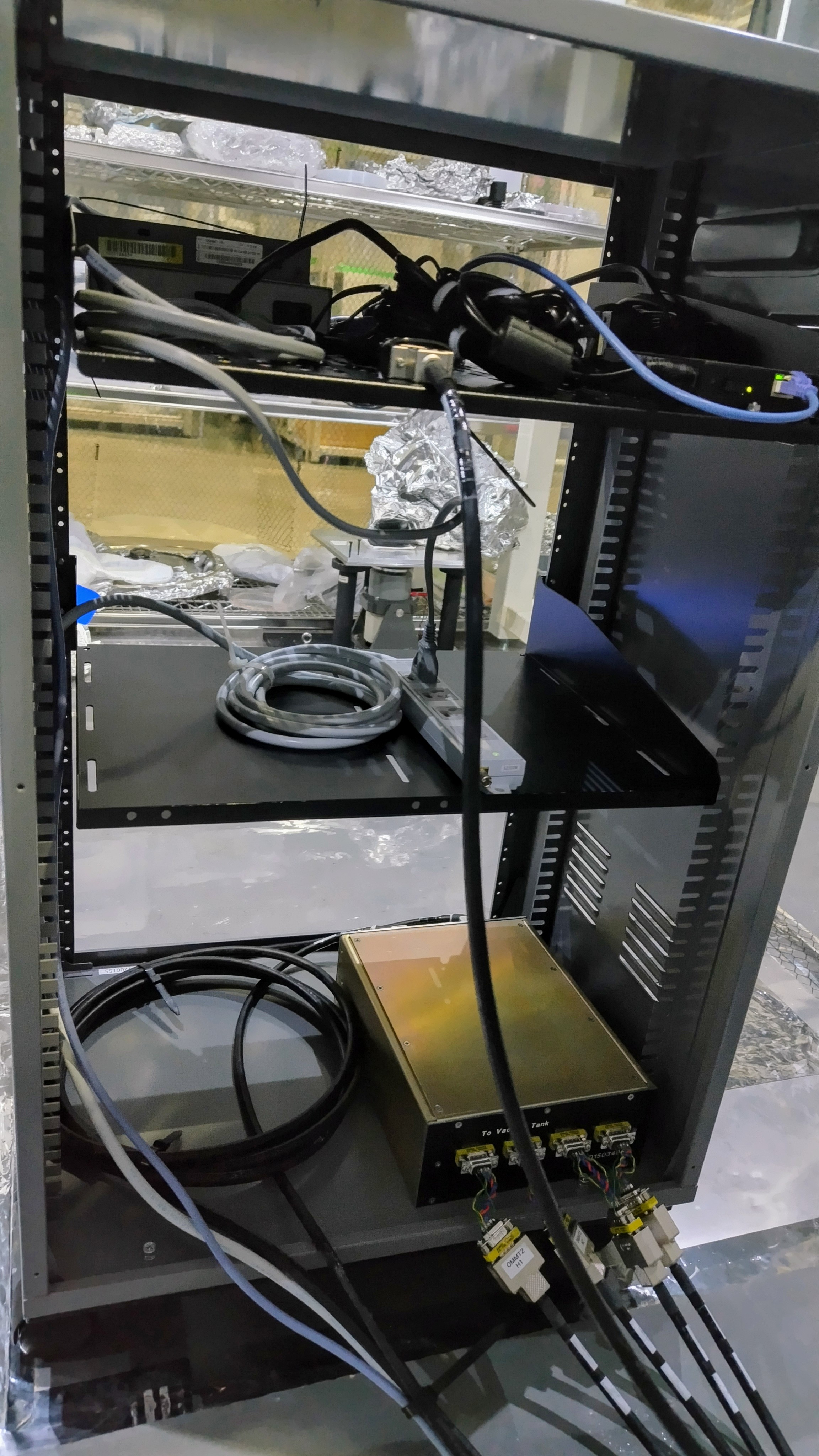
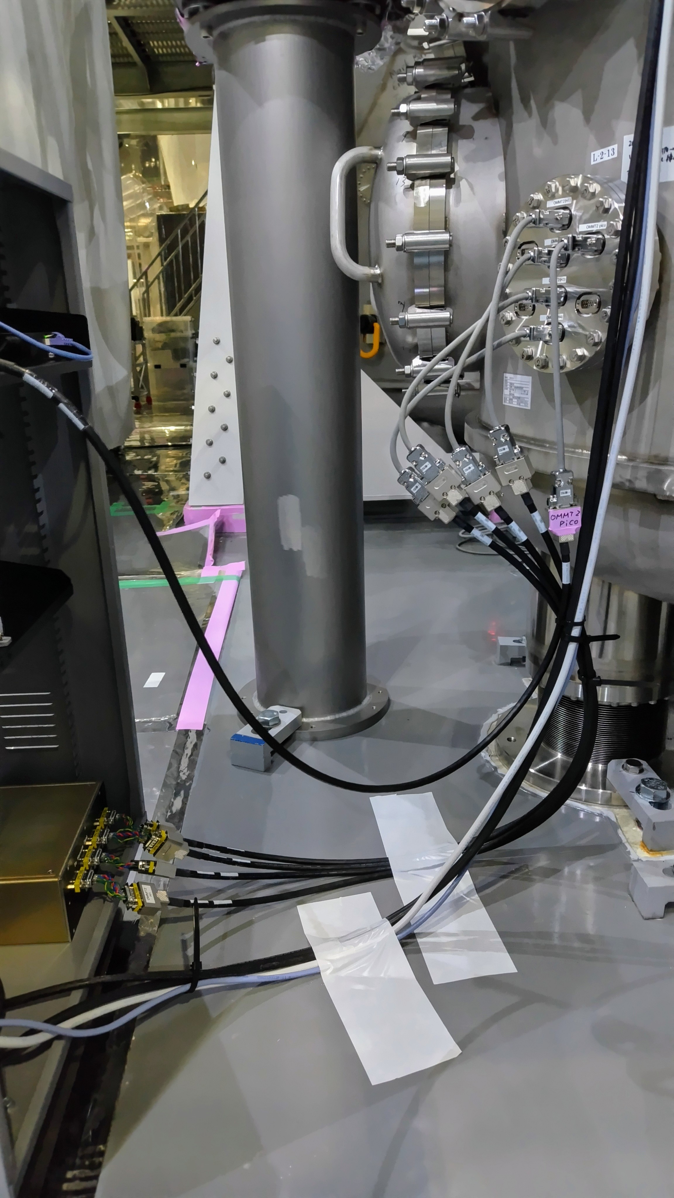
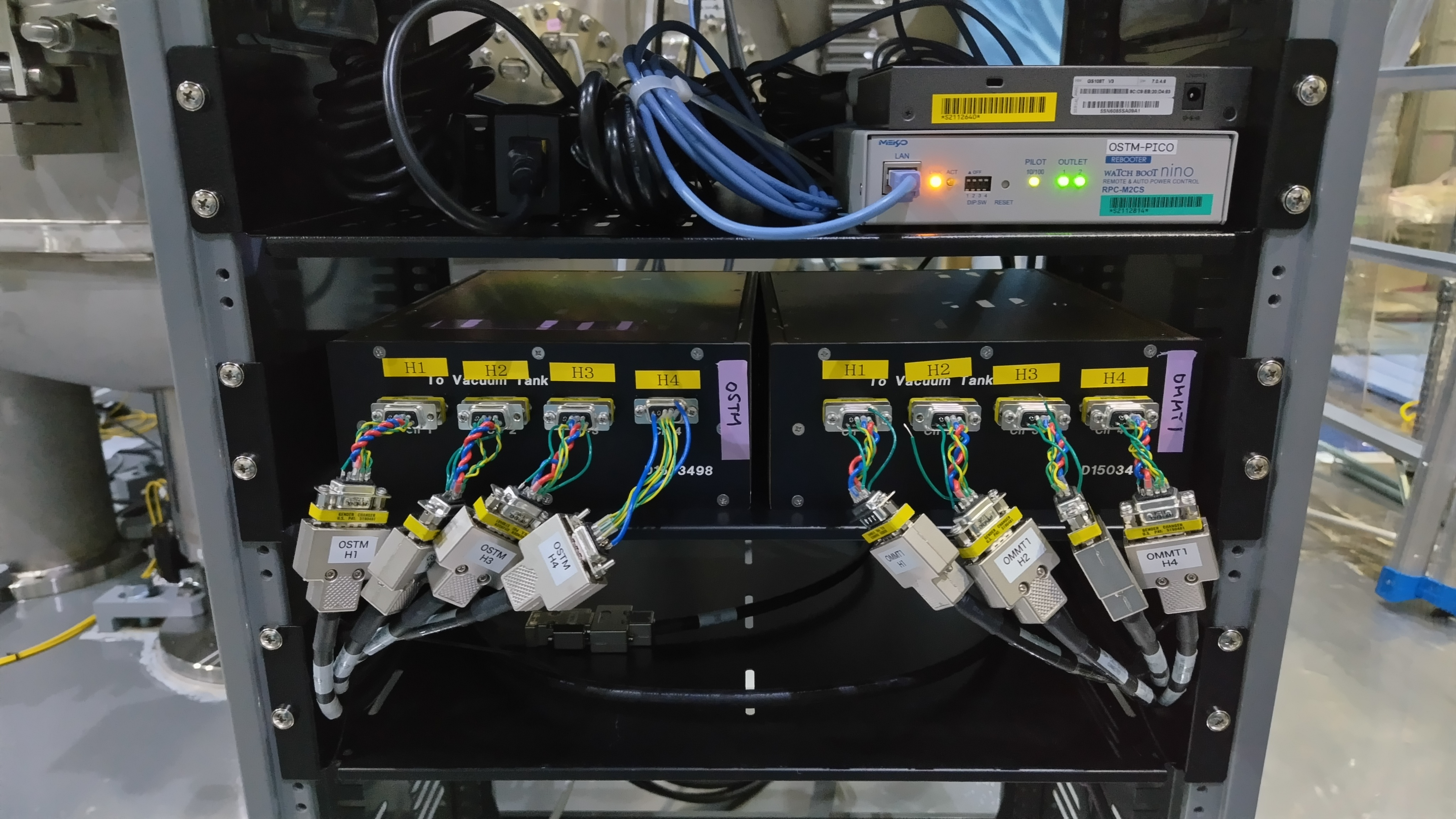
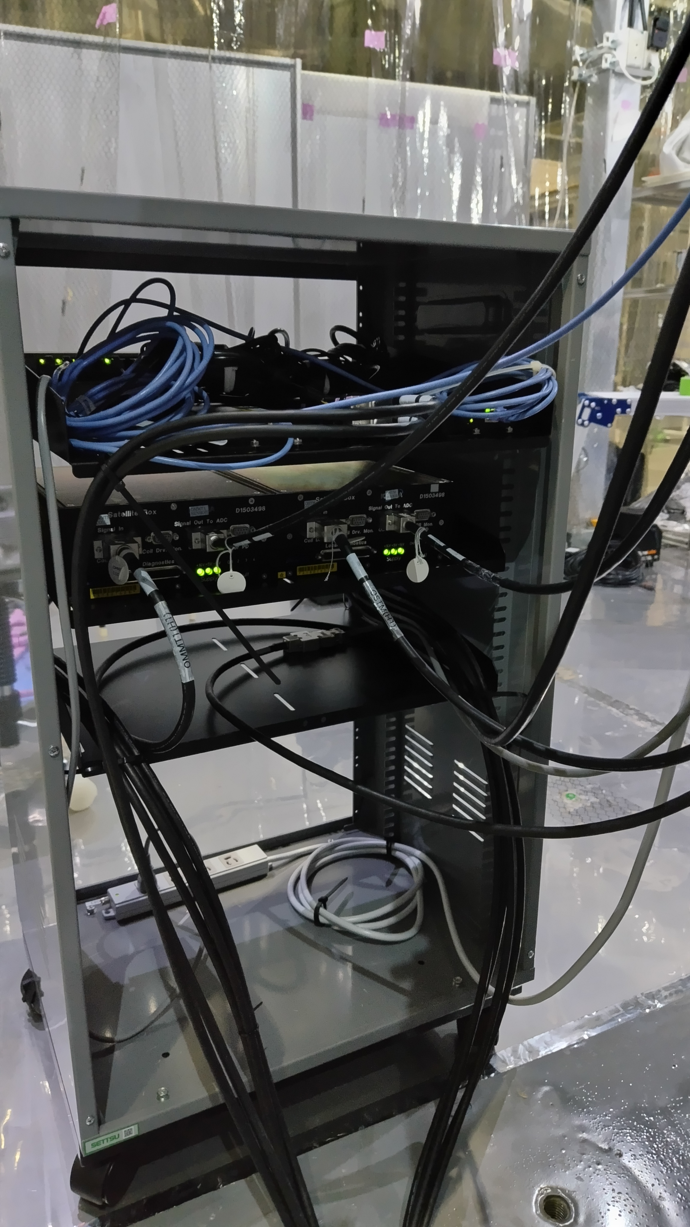
I modified the cabling for the OMM mini-rack as better as possible.

Images attached to this comment
tatsuki.washimi - 16:46 Wednesday 10 July 2024 (30338) Print this report

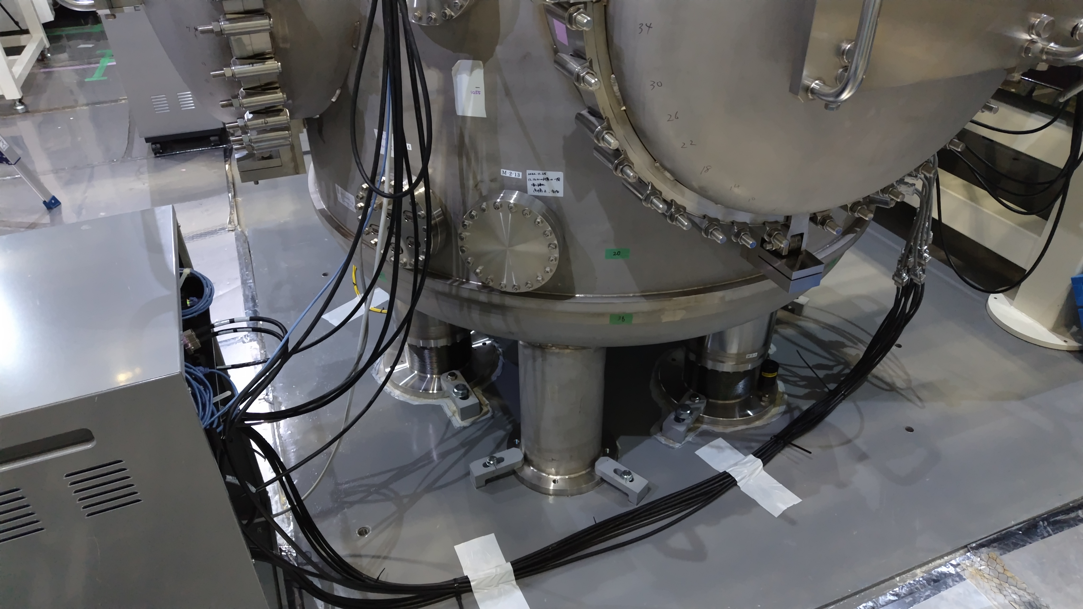
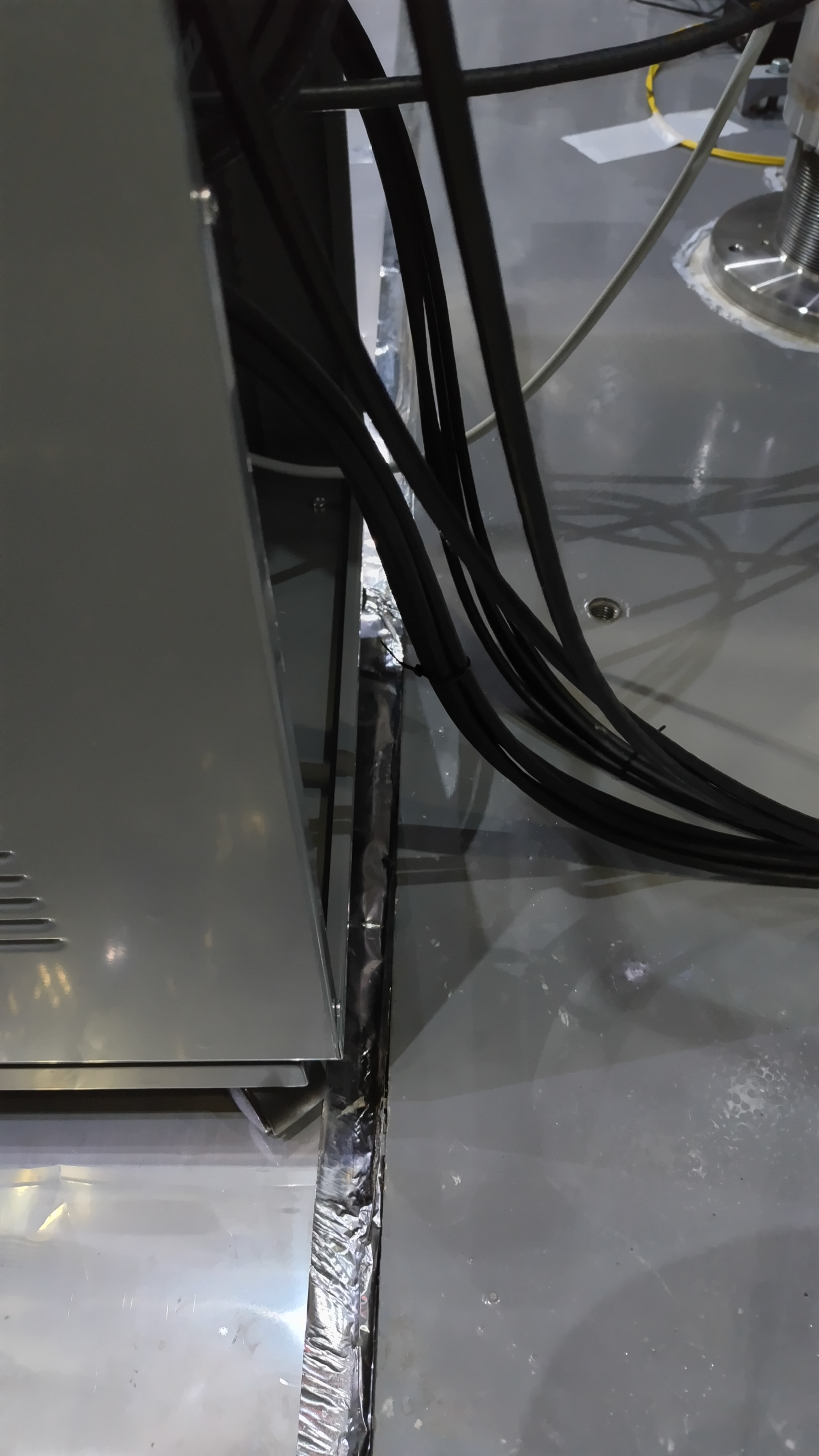
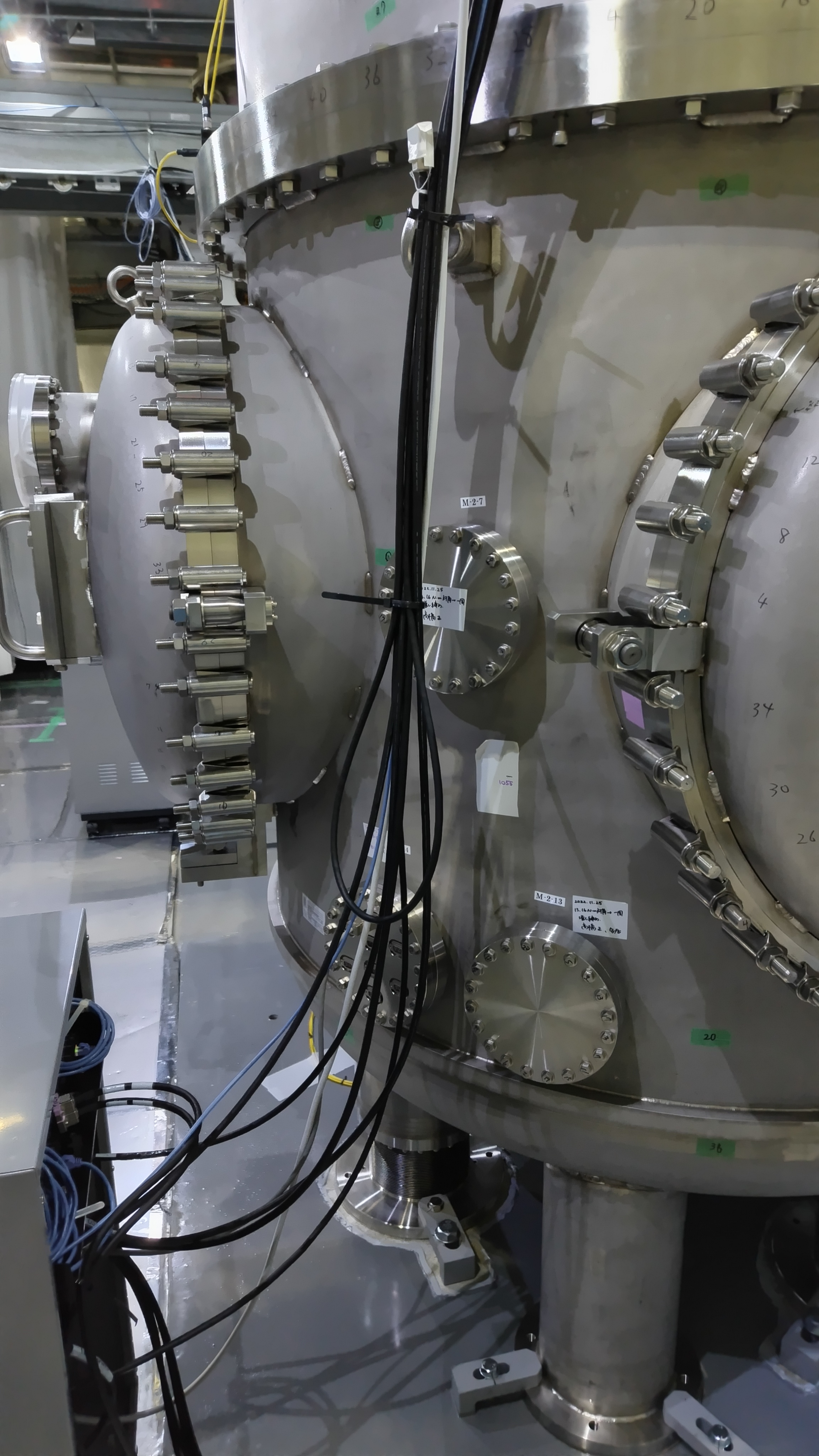
I also modified the cabling for the OMC mini-rack as better as possible.

During this work, I found the shield cable of the H2 and H3 of the OMMT1 were disconnected. (Fig.2)

Images attached to this comment
tatsuki.washimi - 21:46 Wednesday 10 July 2024 (30340) Print this report

I checked each OSEM signal of the OMMT1 and OSEM.

The large 60Hz noise is found in the OMMT1 H3, its shield cable is disconnected.
However, such a large 60Hz noise is not found in the OMMT1 H2, its shield cable is also disconnected.

The OSEM H2 has a large floor noise. Due to the bad centering of the OSEM?

For all OSEM signals, only the 60Hz peaks are large coherence with the OMC chamber ground voltage.  

Between the two suspensions, somehow (OMMT1 H1, OMMT1 H2)x(OSTM H3, OSTM H4) combination have large coherence around 20Hz.

Images attached to this comment
satoru.takano - 19:39 Thursday 11 July 2024 (30367) Print this report

Takano, Yokozawa

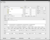
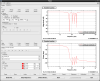
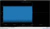
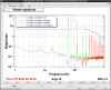
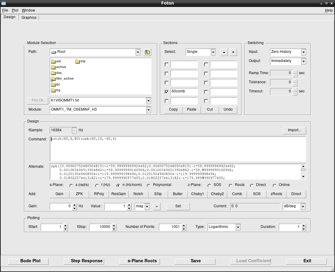
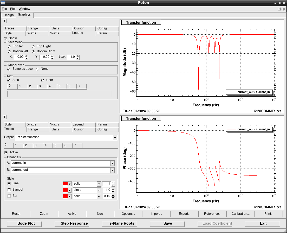
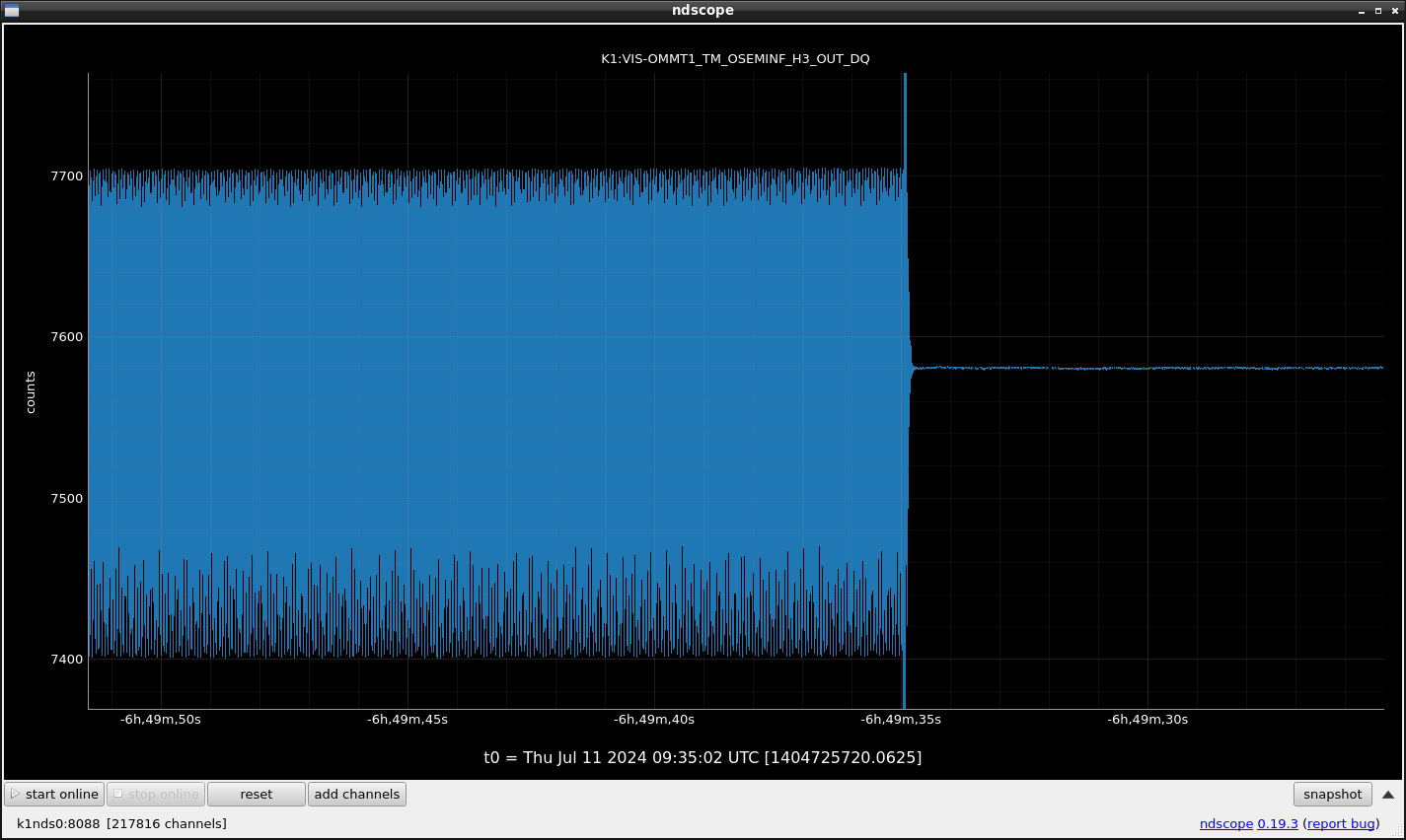
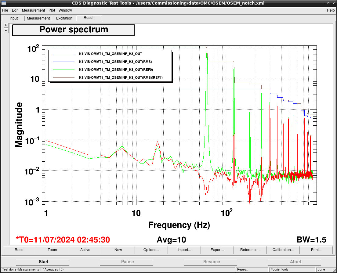
We added a comb notch filter in FM4 of K1:VIS-OMMT1_TM_OSEMINF_H3 temporaly. Figures attached show the setting of the filter, the shape of the filter, the timeseries before and after turning on the filter, and the power spectral density of K1:VIS-OMMT1_TM_OSEMINF_H3_OUT before and after turning on the filter. This filter successfully suppress the harmonics of 60 Hz below 240 Hz.

These files are located in /users/Commissioning/data/OMC/OSEM/ .

Images attached to this comment
takafumi.ushiba - 19:55 Thursday 11 July 2024 (30368) Print this report

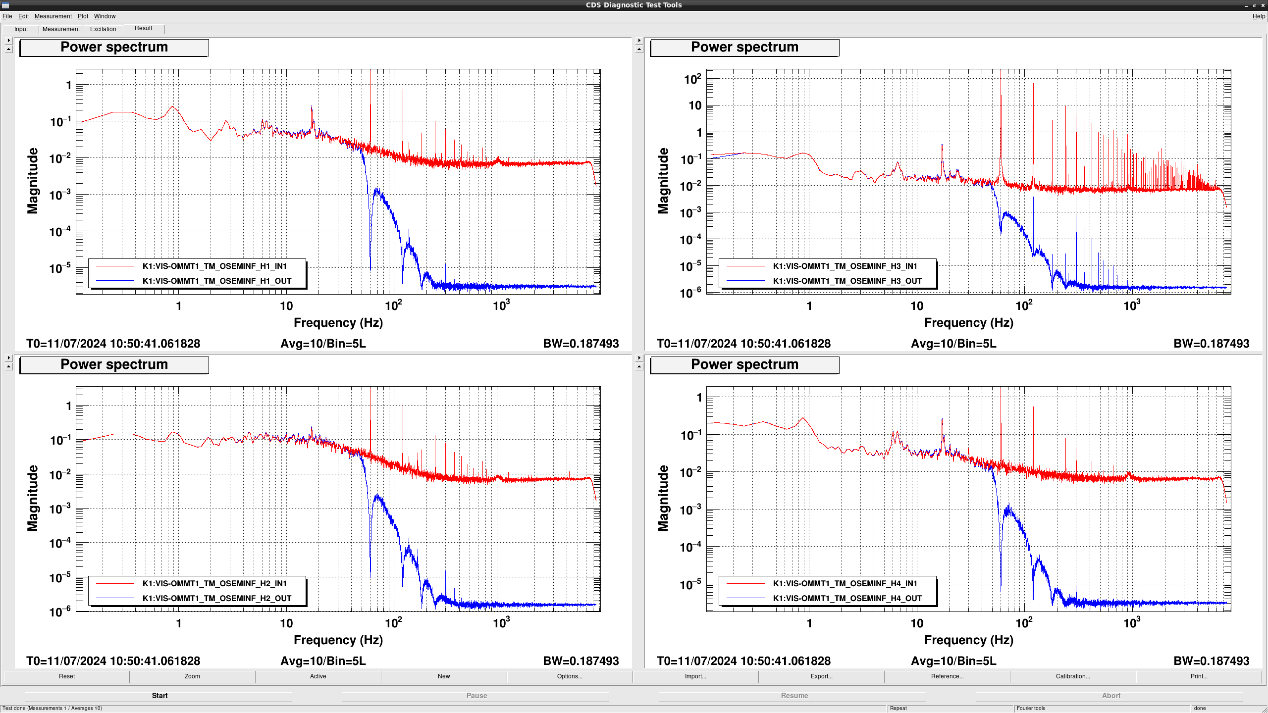
Since RMS seems still limited by harmonics of 60 Hz line, I added 4-th order chebyshef low-pass filter at 50 Hz.
Also, I added the same filter to the other three OSEMs to avoid phase inconsistency between OSEMs.
Figure 1  shows the spectrum at IN1 and OUT of OSEMINF filter bank after implementing new filter.
Below 50 Hz, IN1 and OUT signals are consistent, so we can use these OSEM signals upto 50 Hz for monitoring.

Images attached to this comment
tatsuki.washimi - 9:07 Friday 12 July 2024 (30380) Print this report

The strange behaver of the OMMT1 and OSTM, coherence and cross-talk, was caused by my miss connection of the D-sub cables at the feedthrough.

I fliped the H1 and H2 cables between the OMMT1 and the OSTM.

After yesterday's lunch time, I wen into the mine and fixed it.  

tatsuki.washimi - 14:17 Tuesday 16 July 2024 (30423) Print this report

I pasted green tapes for the OMMT1 cables and pink tapes for the OSTM cables, to avoid future mistakes.

Images attached to this comment
tomotada.akutsu - 18:30 Tuesday 16 July 2024 (30435) Print this report

Thank you for your efforts. By the way, the other day Kimura-san pointed out that the hermtic Dsubs should be stress-released to avoid leak happening. It might be wished to do some stress-releaving for those cables.

tatsuki.washimi - 19:15 Tuesday 16 July 2024 (30437) Print this report

Someday I discussed with Kimura-san. If my memory and understanding are correct, the problem is the stress on each pin, and it is OK if D-sub connectors are fixed held by the screws and connected vertically to the feedthrough. These flip cables for the OSEMs are well-fixed correctly.
Problemable connectors are those held by pins, not by screws. (I suspect the cables of PZT and Zswitch, using double gender-changers for each, could be such a situation.)

Search Help
×

Warning

×