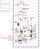
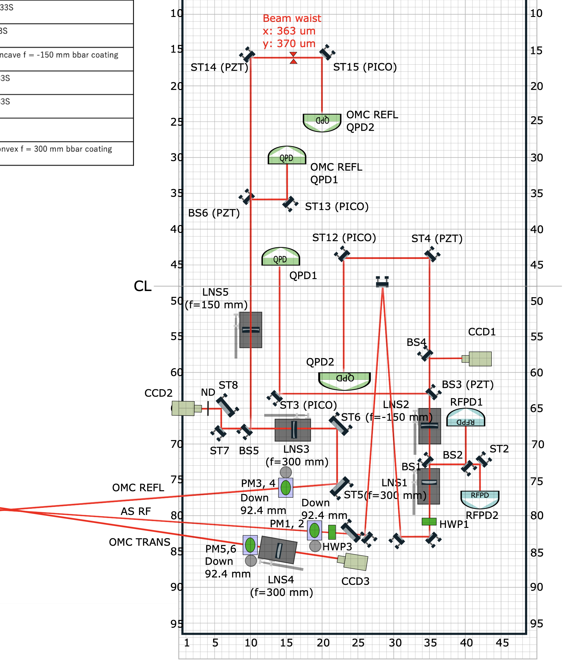
We performed the AS RF beam path at AS table.
- Check the beam spot for the periscope1,2
Beam spot on the periscope1 was slightly +Y direction, but no problem, that on the periscope2 was center.
- HWP3
I moved +Y direction for pathing the center
- lower 3 mirrors
Touched by pathing the center and inject the beam dumper
- remaining two mirrors before HWP1
Bu centering the LNS1 and LNS2, I tweaked both mirrors (near the HWP1 : LNS1, far the HWP1 : LNS2)
- Tweaked the BS2 and ST2 by injecting the RFPD1 and RFPD2
- Sorry, I noticed we didn't touch the BS4 for injecting the beam to CCD1, we will check later
- By injecting the beam to both QPDs, we tweaked the ST4, ST12, BS3, ST3 by my eye check
- To check the working of the pico motor, I performed the QPD1 and QPD2 centering by the pico motors, that worked well
I also performed the alignment of the OMC REFL path. Pico motors in the path seems to work well.
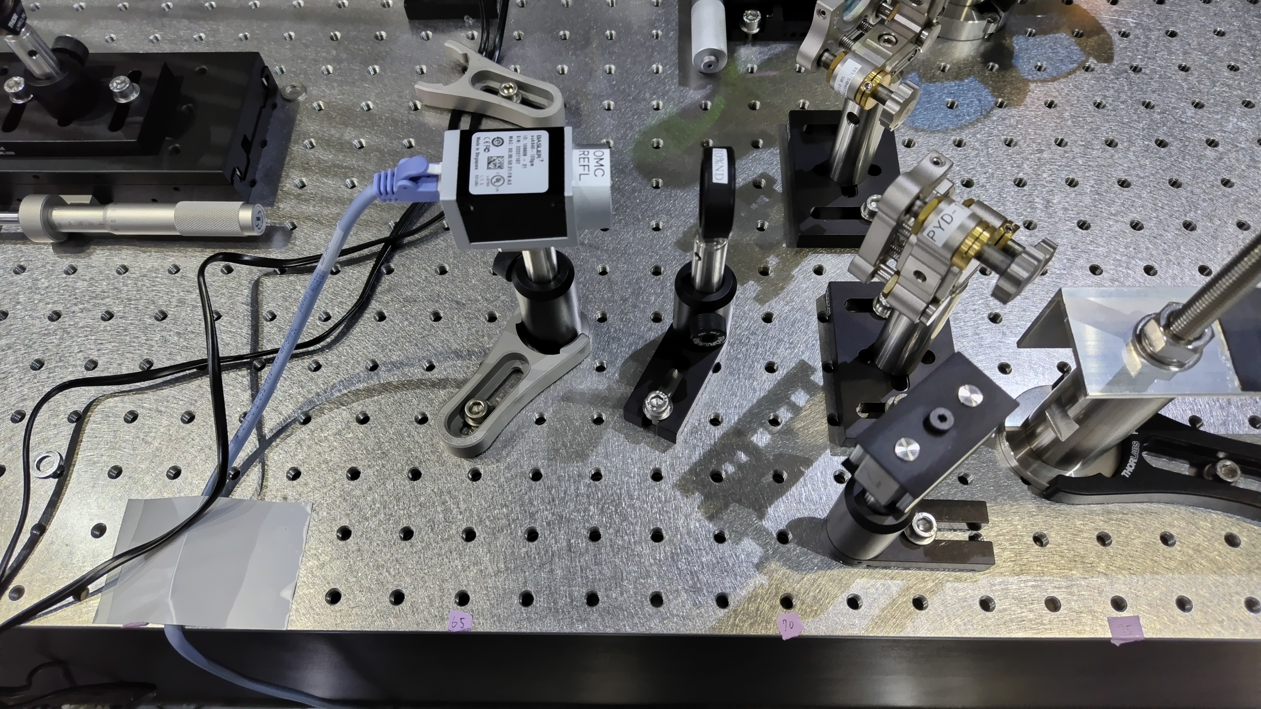
During the OMC REFL beam path alignment, we found the ND filter in front of the CCD camera is damaged.
Currently, an absorption type ND filter seems to be used but it should be reflection type (and reflection beam should be propery dumped) because the laser power to OMC REFL becomes sometimes very high.
We will relocate the CCD2 position because it will be out of the covering when we will set the ASC table cover.
The CCD2 position and direction are not correct in the drawing.
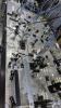
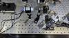
Anyway, to assemble the walls on the AS table, the optics on it should not be located near the outer edges of the table, because the wall footprint will come to the edge lines with some thickness. I am not sure the required thickness to stand the walls, but seemingly some of the optics should be moved, in the end.
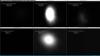
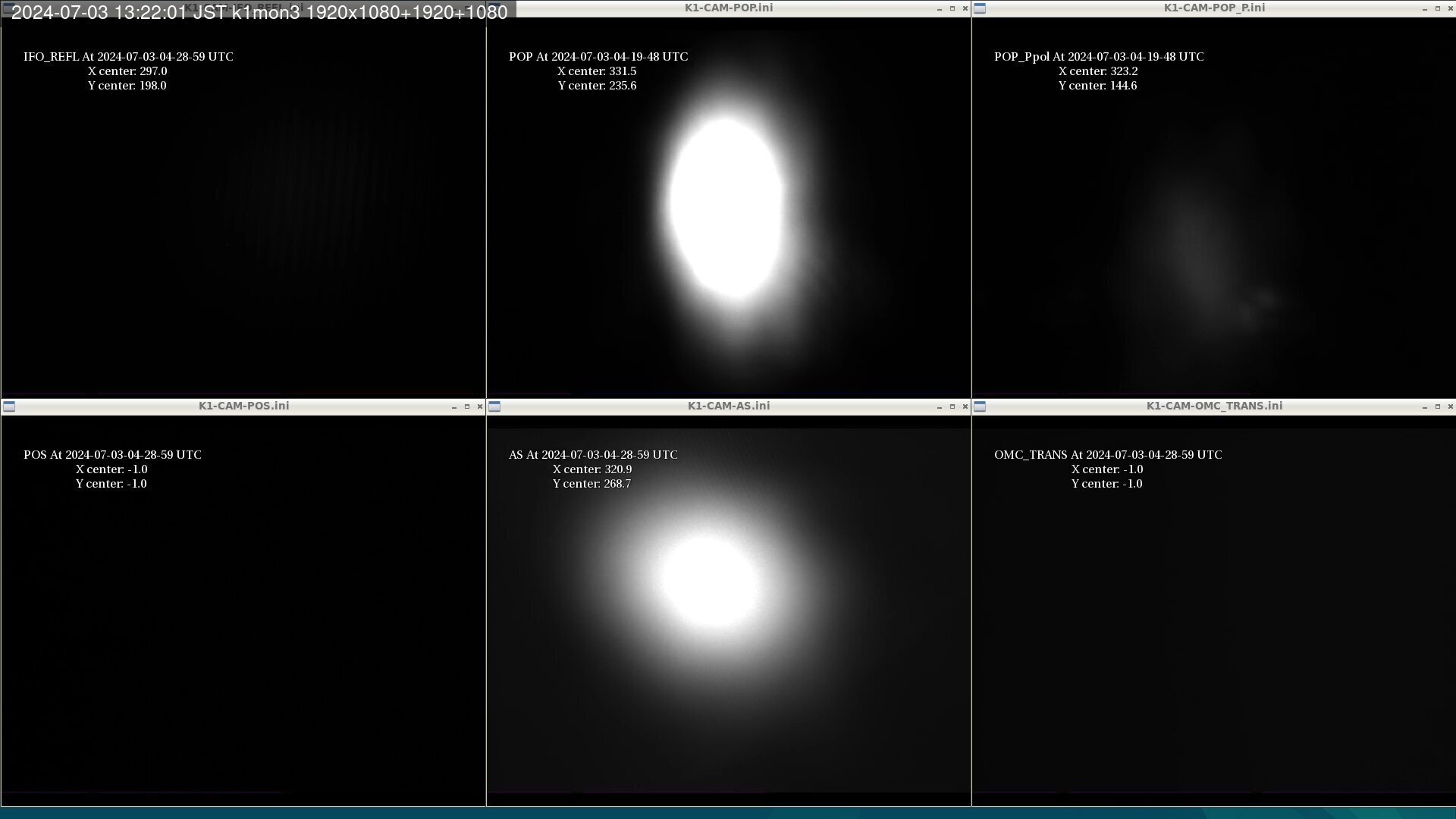
We forgot to perform the alignment to AS camera. So we did it. Fig.1 shows the results. Now, the AS beam hits on the center of the AS camera.
And we found that the beam did not hit on AS RF PDA1. (we are not sure of the reason). So we aligned the beam to hit on the center of the PD.