Reports 1-1 of 1 Clear search Modify search
VIS (OMM)
ryutaro.takahashi - 18:48 Tuesday 11 June 2024 (29837) Print this report
Preparation for hanging of optical bench

[Washimi, Takahashi]

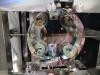
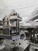
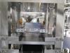
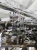
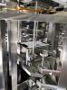
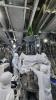
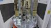
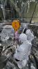
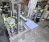
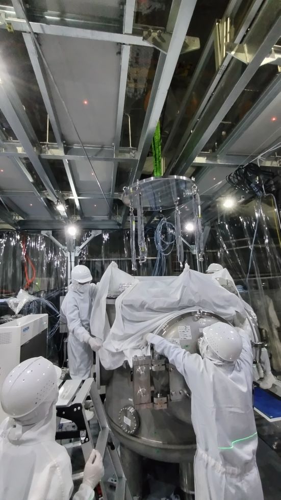
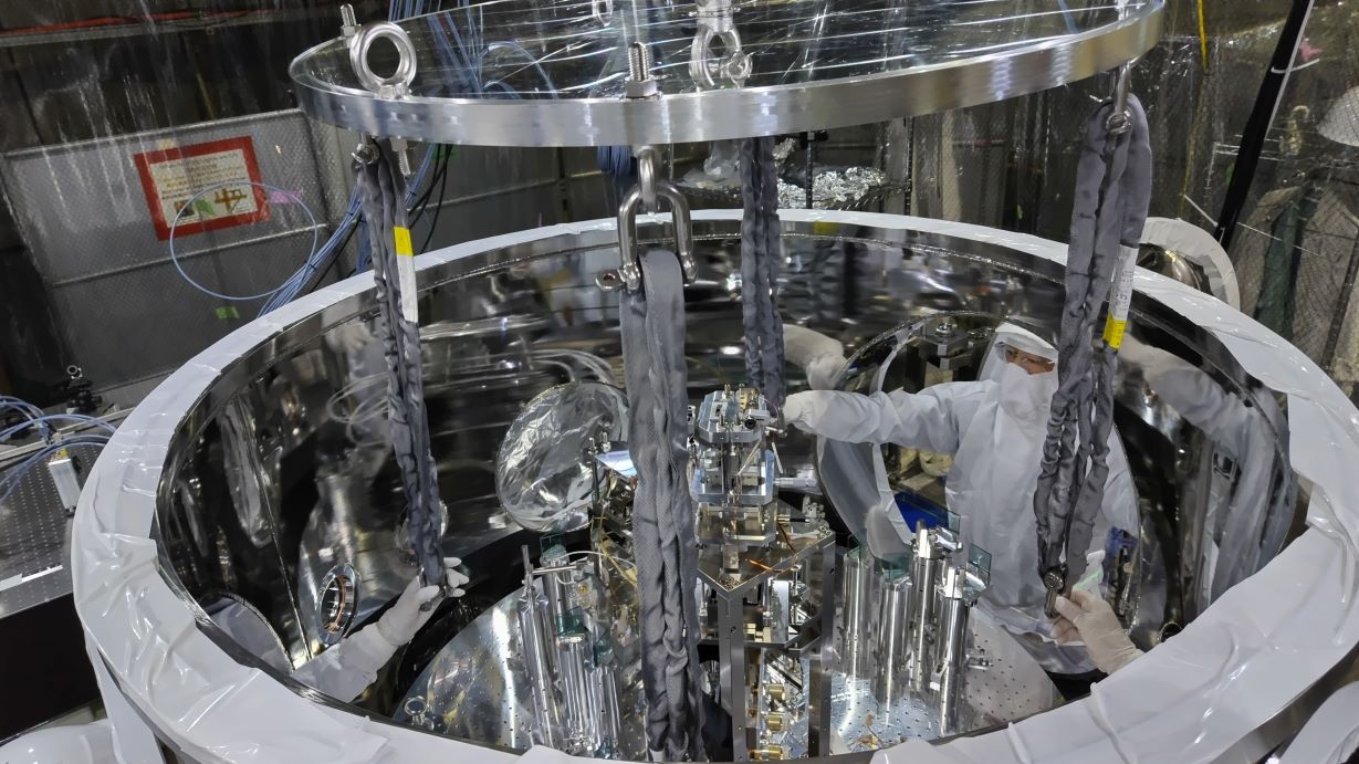
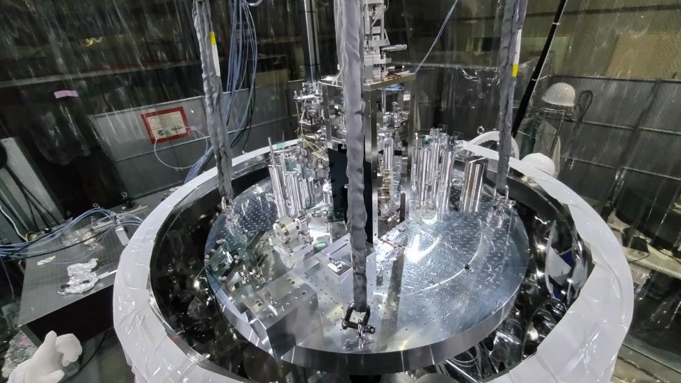
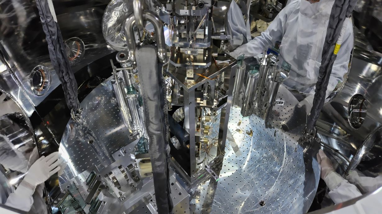
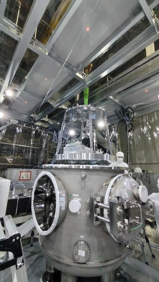
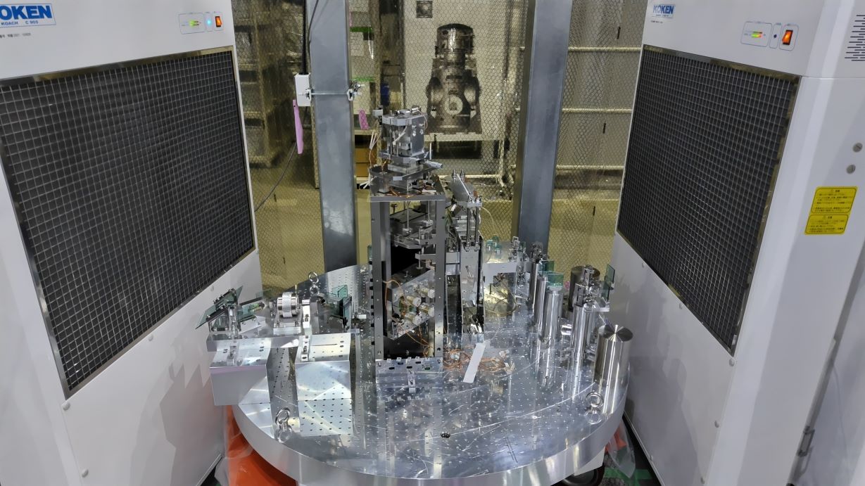
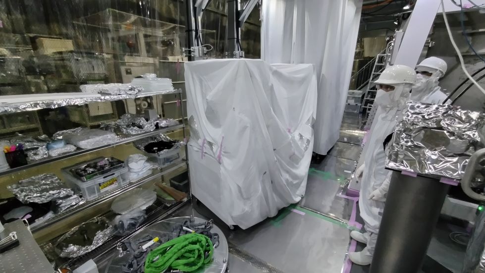
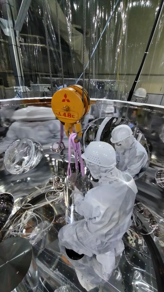
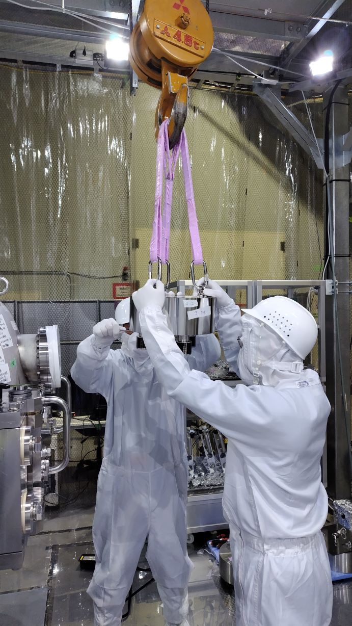
We prepared to hang the optical bench in the OMC chamber.

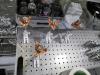
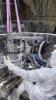
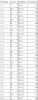
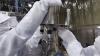
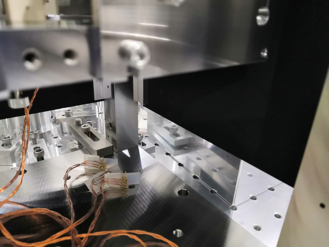
  1. Tagged the connectors and cables. The cables were disconnected from the suspensions and the PD pod, and put on the base plate.
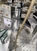
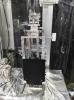
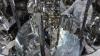
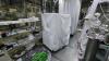
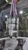
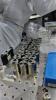
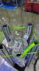
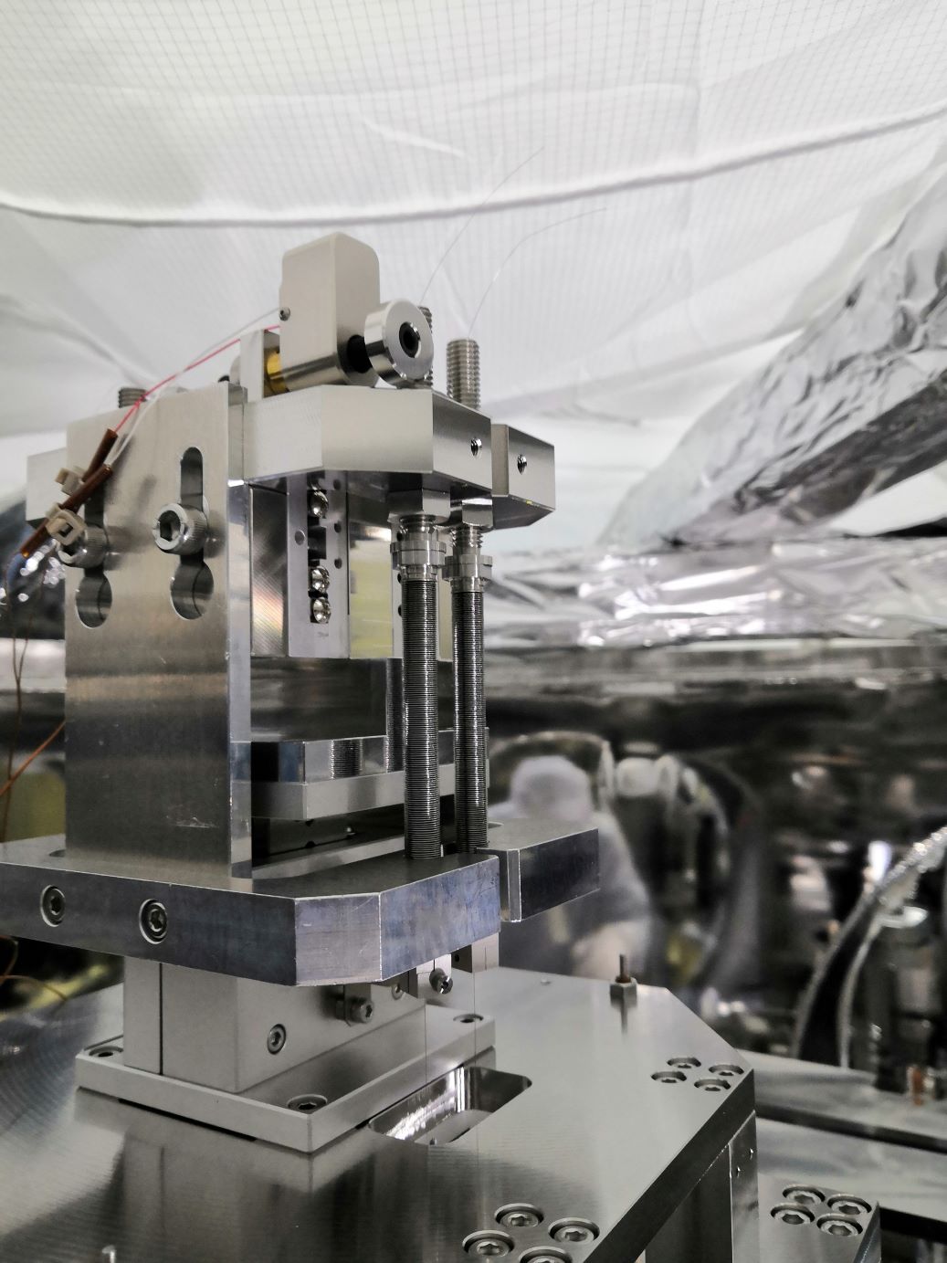
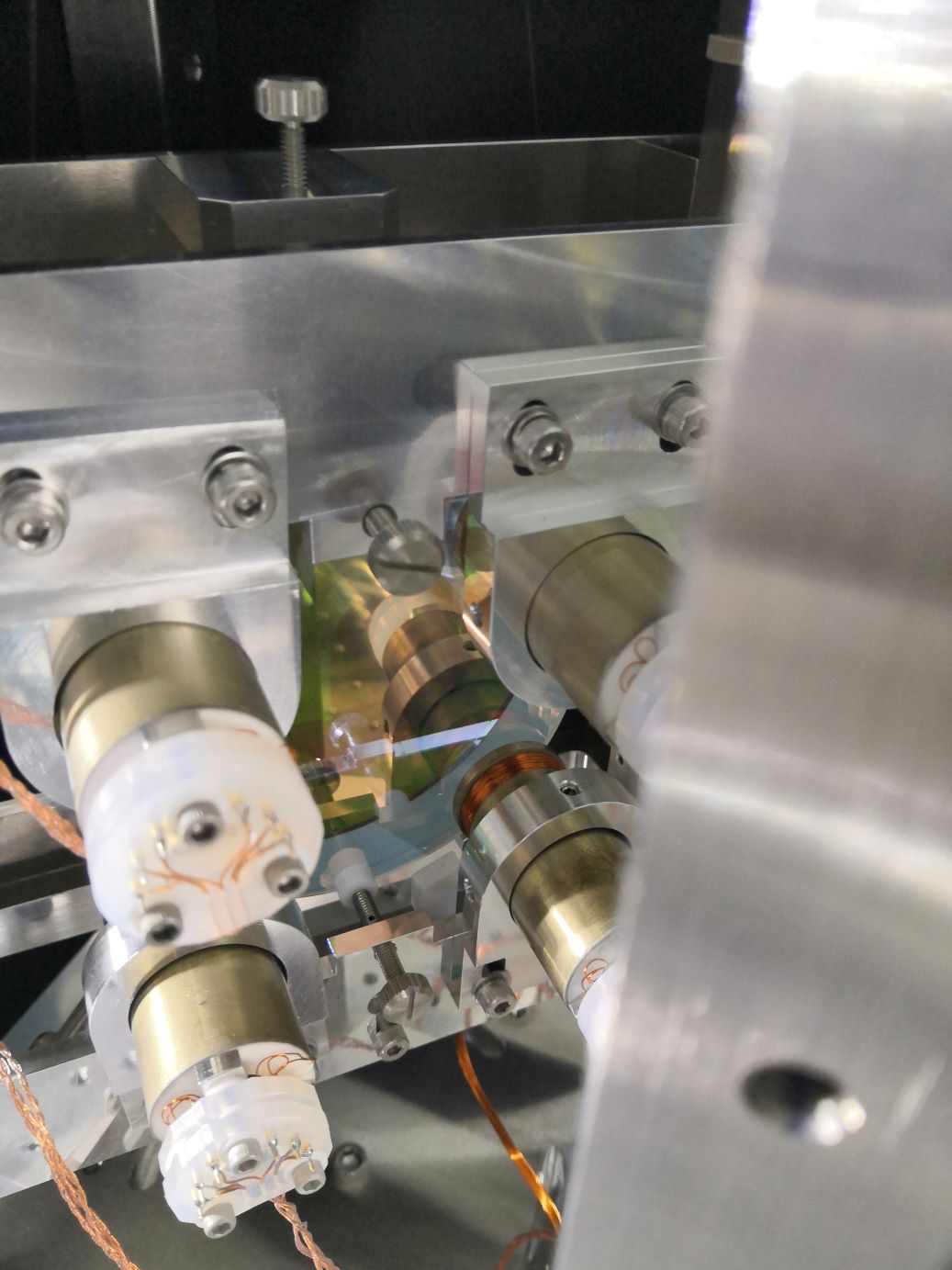
  2. Fixed the OMMT1 suspension. The TMs were locked with the EQ stoppers. The bellows springs were locked with the special jig. The IM and  IRM  were locked with the support stage.
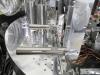
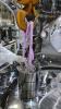
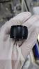
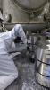
  3. Fixed the OSTM suspension. The TMs were locked with the EQ stoppers. The bellows springs were locked with the special jig. The IM and  IRM  were locked with the support stage. Unfortunately, one suspension wire for the TM was cut. It is necessary to rehang the suspension.
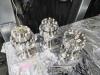
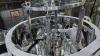
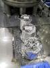
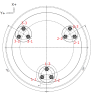
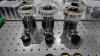
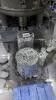
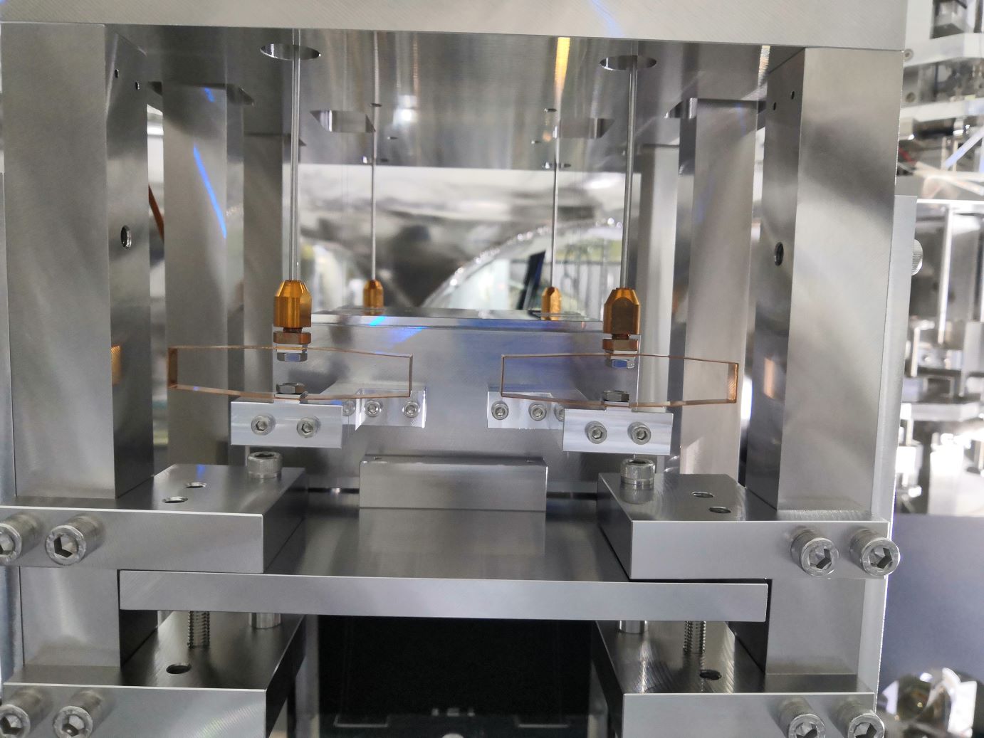
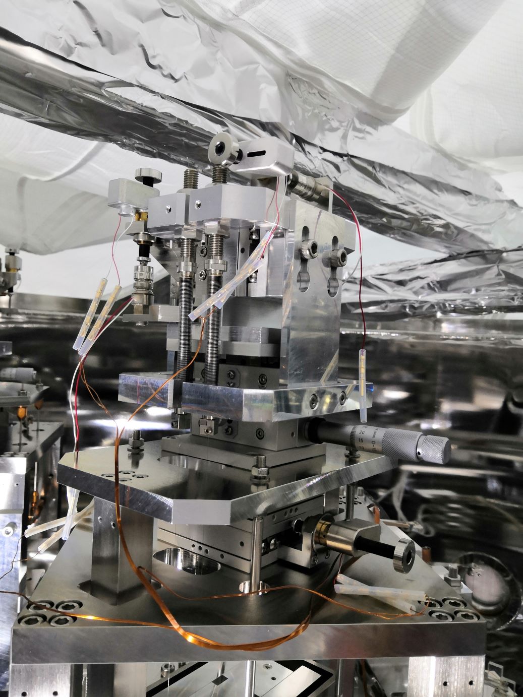
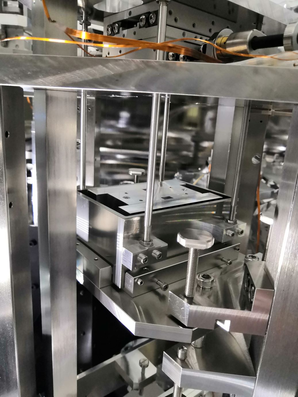
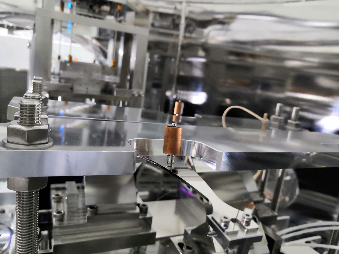
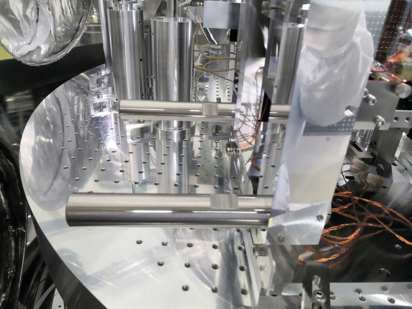
  4. Fixed the OMC suspension. The optical bench was locked with four screws. Since one screw was stuck, a small spacer was inserted there. The blade springs were locked with the upper bars. The flexible damping magnets were removed.
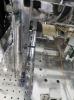
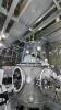
  5. Removed the PD pod.
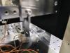
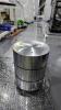
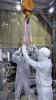
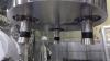
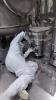
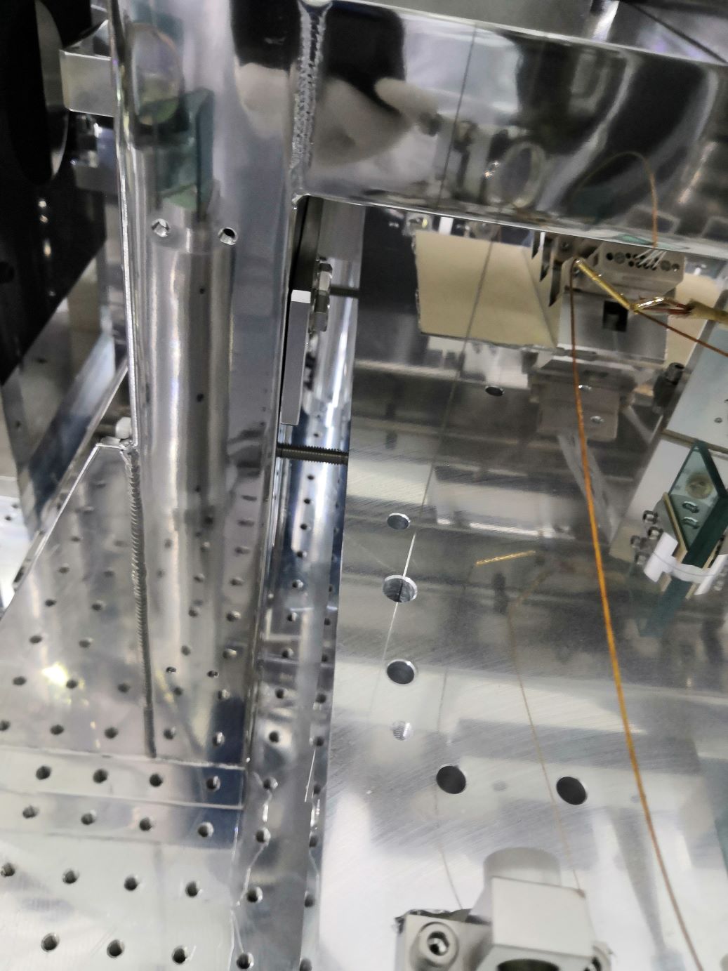
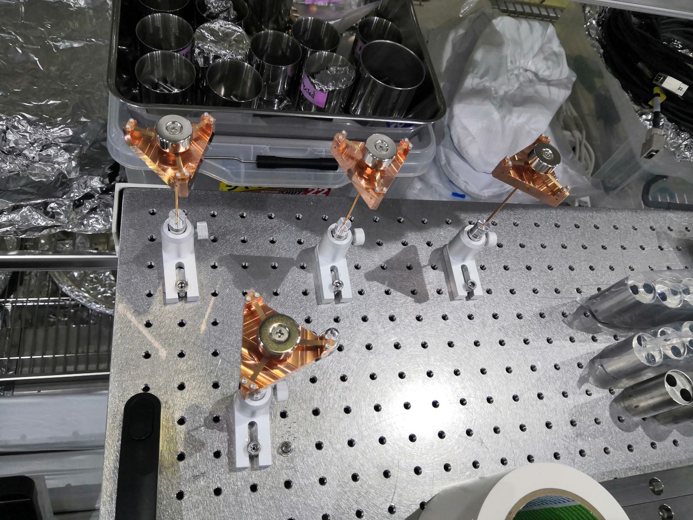
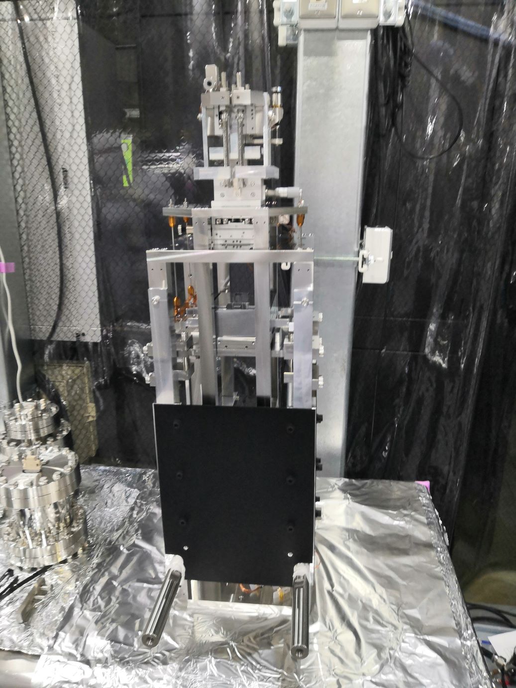
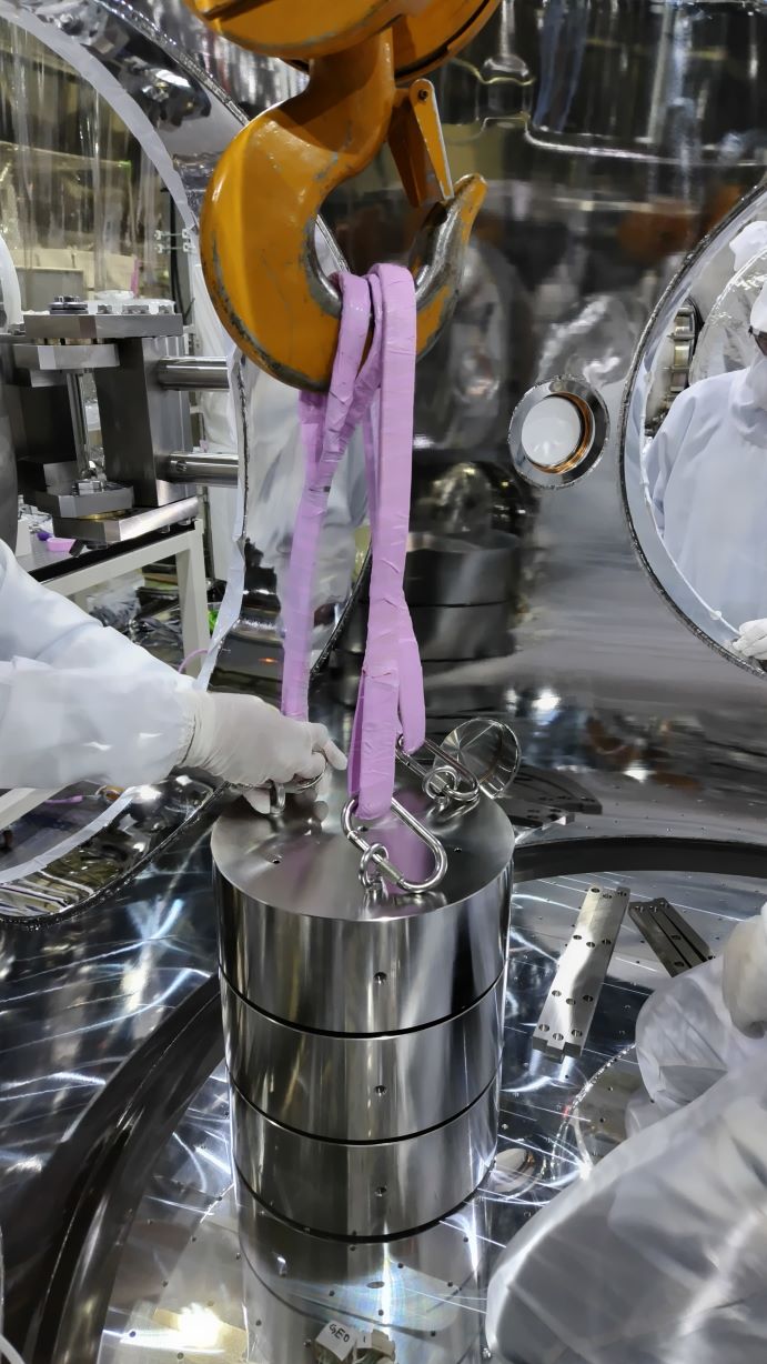
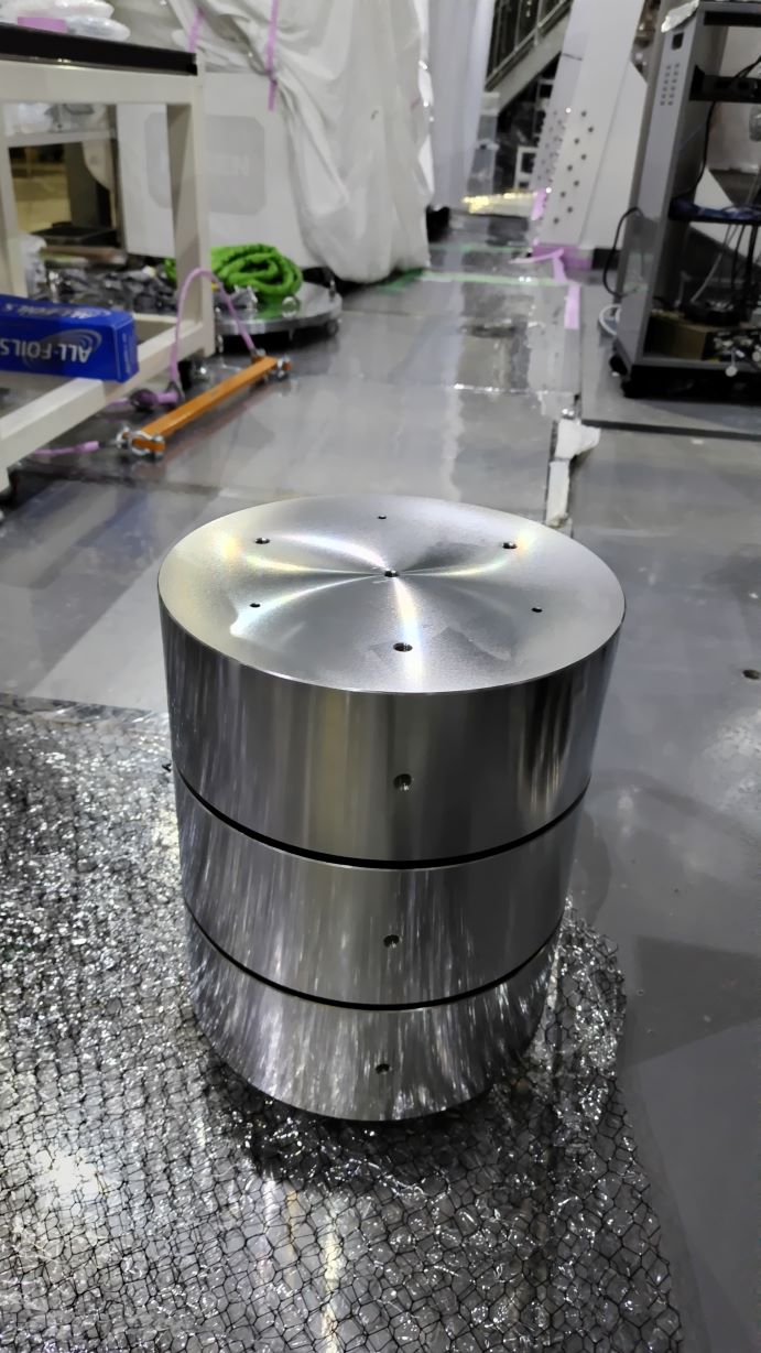
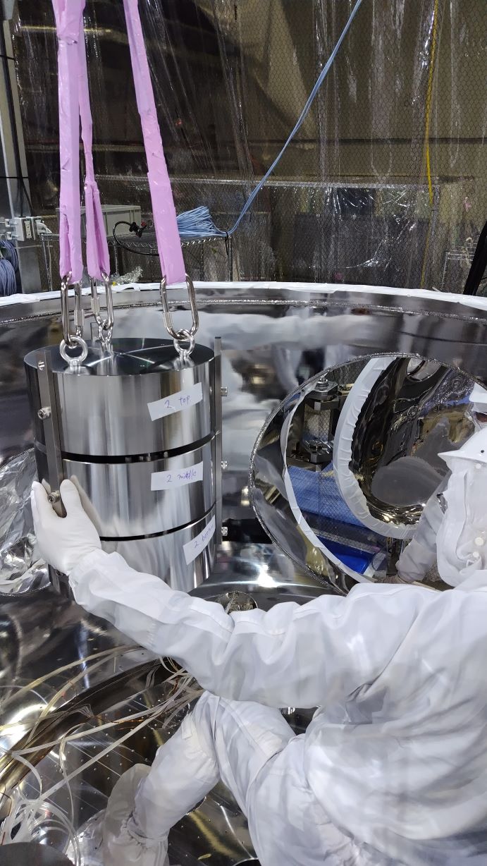
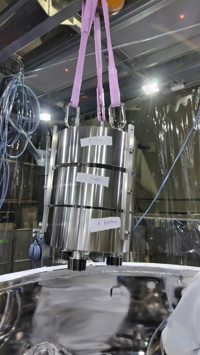
  6. Marked the position of the OMMT1 suspension with clamps. The handling rods were attached to the suspension frame. The OMMT1 suspension was removed.
Images attached to this report
Comments to this report:
ryutaro.takahashi - 22:16 Wednesday 12 June 2024 (29864) Print this report

[Kimura, M.Takahashi, Yasui, Nakajima, Washimi, R.Takahashi]

We removed the optical bench and the stack legs from the OMC chamber.

Optical Bench

  1. Attached the disk balance suspended from the crane to the optical bench.
  2. Hung the optical bench a little. The tilt of the bench was adjusted by the counterweights of 20kg (8kg x1, 4kg x3). Though there was still an unbalance, it seemed acceptable.
  3. Hung the optical bench up so that the bench could clear the chamber wall.
  4. Moved the bench onto the hand lifter (Bishamon) with the wood base (Makuragi).
  5. Moved the bench on the hand lifter to the storage space. The KOACH filters were set on both sides of the bench and covered by a clean bag.

Stack Legs

  1. Attached three connection jigs to the SUS blocks of the 1st stack leg.
  2. Hung the combined stack leg up with the crane.
  3. Moved the stack leg onto the floor on the line for the crane.
  4. Repeated the hanging for the other two legs. Since these legs were offset from the crane line by 43cm, we needed to push horizontally by our hand with 13kgf.
  5. Covered the stack legs with aluminum foil.
Images attached to this comment
ryutaro.takahashi - 20:26 Thursday 13 June 2024 (29895) Print this report

[Takahashi, Washimi, Ito]

We reassembled three stack legs.

  1. Lifted each SUS block up with the crane.
  2. Disassembled the bellows, spacers, and rubbers. The screws for two bellows flanges (1-2 and 2-2 bottom) were not fastened.
  3. Replaced the upper spacers with the 1.8mm longer ones.
  4. Replaced the rubbers with the harder ones. Details are summarized in the table.
  5. Enclosed the spacers and rubbers with the bellows. The flanges for the bellows were sealed with the Al gasket in the torque of 8Nm. M6 stop screws and thin nuts (3.6mm) were used.
  6. Assembled SUS blocks were stacked.
Images attached to this comment
tatsuki.washimi - 14:33 Friday 14 June 2024 (29913) Print this report

[Takahashi, Washimi, Ito]

In this morning, we performed the weight test for the new stacks:

  1. Measured the gaps for each rubber (top, middle)
  2. Loaded the weight: 153kg for the Stack1, 159kg for the Stack2, and 155kg for the Stack3
  3. Measured the gaps for each rubber (top, middle) again
  4. Constructed the safety jigs

The measured gaps and spring constants are plotted here.
The spring constant's mean and standard error(σ/√N) is 533±26 N/mm. (see also the Mitaka test: klog29651)

Images attached to this comment
tatsuki.washimi - 14:03 Monday 17 June 2024 (29937) Print this report

We measured the gaps between each stage of the new stacks, after this weekend.

The average gap size was changed as 8.84 mm -> 8.69 mm (top), and  8.34mm ->  8.10 mm (middle).

Images attached to this comment
tatsuki.washimi - 15:29 Monday 17 June 2024 (29942) Print this report

We measured the hardness of the rubbers derived from the old stacks.


     top   middle bottom
1-1 74 74 77
1-2 74 76 76
1-3 74 76 77
2-1 74 77 73
2-2 74 74 76
2-3 74 76 76
3-1 72 73 76
3-2 73 73 76
3-3 73 76 75


tomotada.akutsu - 16:14 Monday 17 June 2024 (29944) Print this report

By the way, which distance of the parts is referred as "gap" here? For example, the head of hexisagonal screw and the nearest stack surface? Some drawings to explain the situation would be wished.

tatsuki.washimi - 16:33 Monday 17 June 2024 (29945) Print this report

It means the distance between bulk surfaces.

Images attached to this comment
tatsuki.washimi - 9:26 Tuesday 18 June 2024 (29954) Print this report

the nominal hardness of the old rubbers is 70 (top) and 80 (middle and bottom), according to information from Mirapro.

Search Help
×

Warning

×