Reports 1-1 of 1 Clear search Modify search
MIF (General)
takafumi.ushiba - 23:18 Tuesday 14 May 2024 (29504) Print this report
Check of the beam spot on SR3

Continued work from klog29478.

[Aso, Hirata, Ushiba]

Abstract:

We checked IR beam spot on BS, which is reflected by ITMX and BS.
Beam spot on SR3 is shifted 1-2 cm along +X direction and 1.5-2.5 cm along +Z (vertical) direction now.

Detail:

Alignment of XARM and BS were performed with the same manner as reported in klog29478.
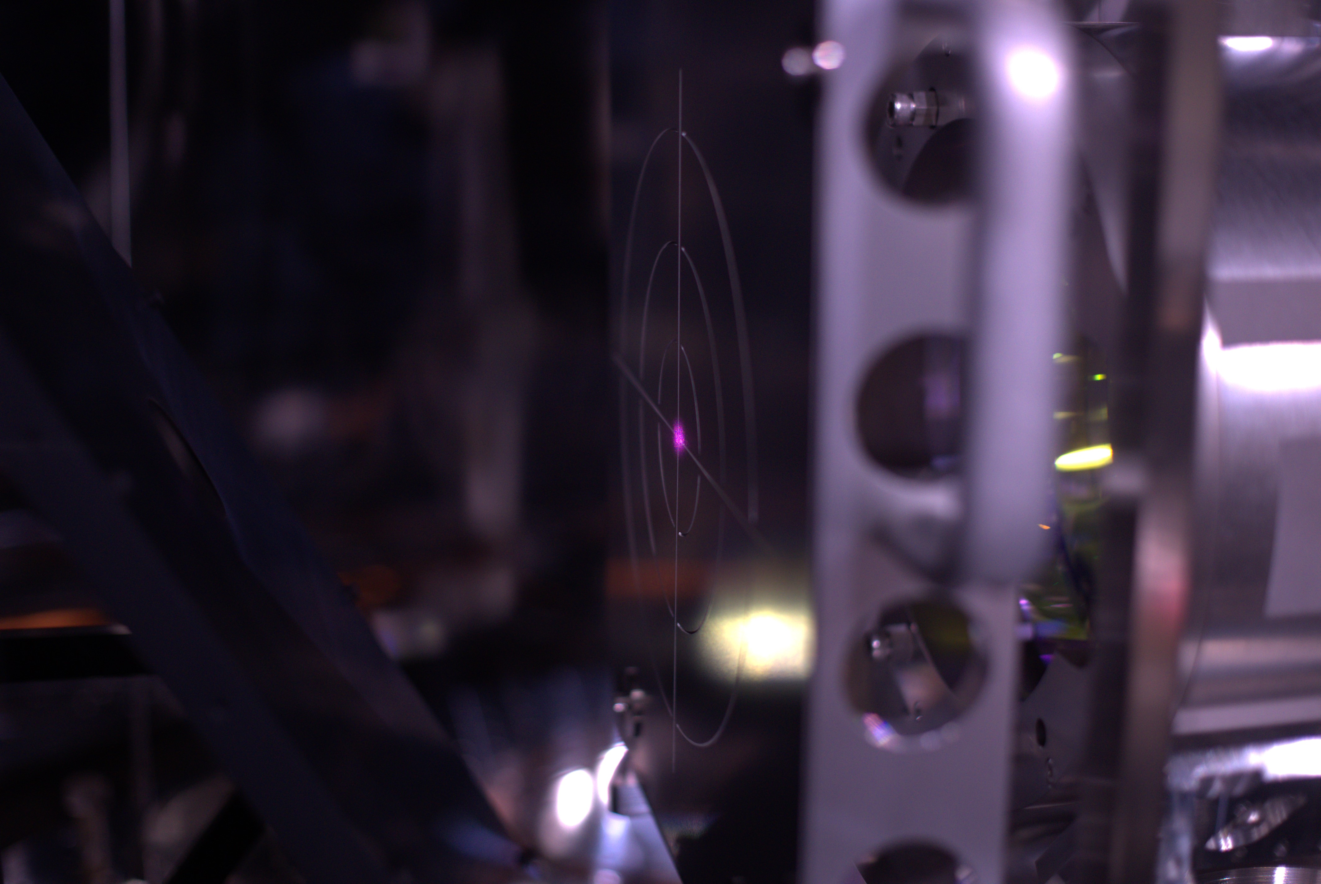
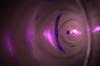
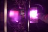
Then, we set target on SR3 and checked the beam spot with respect to the target center.
It seems 1 or 2 cm shifted along +X direction and 1.5 or 2.5 cm shifted along +Z direction (we forgot to take the picture out from the camera, so we will post the picture later).

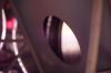
Then, we also take the picture around mid-baffle apature from BS side and SR3 side to confirm if IR beam is clipped or not: it seems no large clip fortunately.
We will check the beam spot on SR2 tomorrow.

Note:

Initially, we though IR alignment is not good (IR normalized trans power is only 0.8 now) and that results in the shift of IR beam spot on SR3.
So, we checked TMSX optics and realignment of several in-air optics on TMSX optical table (this will be reported in different post later).
However, TMSX alignment is not change the situation (we plan to check the beam spot on SR3 again because we haven't check the beam spot after realigning TMSX optics, but since the alignment change is not so large, SR3 beam spot recovery is almost no hope...).

In addition, according to the fig4 in klog29261, beam spot on PR3 was shifted about 1cm along -Y direction and 2cm along +Z direction.
So, reflected IR beam can hit on +X/+Z direction on SR3, so current SR3 beam spot might be not so strange with a large shift of the beam spot on the ITMX.

Anyway, we will also try to investigate where 20% loss of X arm transmission comes tomorrow.

Comments to this report:
satoru.takano - 2:10 Wednesday 15 May 2024 (29507) Print this report

Just a comment for the power loss.

If 20% loss was induced by clipping of the beam, the edge of the clipping object is about 0.6*[beam radius] from the center as attached. Such a clipping should be visible by eye, therefore the 20% loss seems not to come from the clipping at somewhere but incomplete alignment.

Images attached to this comment
shinji.miyoki - 6:26 Wednesday 15 May 2024 (29508) Print this report

The beam spot change on PR3 will affect the position changes also at the GV window between IXC and BS?

Originally, the beam should pass around the center in this window (actually slight shifting is expected to compensate for the very slight wedge effect of this window for the EXC position). This means that a slight shift at this window will result in a not-small change of passable beam power and beam mode because the beam has the strongest intensity distribution at the beam center as a Gaussian beam.

So, could you please consider not the edge clipping but the center area clipping assuming the beam is now passing through the limited aperture at GV between IXC and BS? According to my faint memory, the aperture size is 15cm?

takafumi.ushiba - 13:30 Wednesday 15 May 2024 (29513) Print this report

We checked the IR beam on SR3 again and found that the beam we saw yesterday might be overlapped beam with ITMX reflection and ITMY reflection because of the lack of the amount of misalignment of ITMY.
Today, we misaligned ITMY by 4.2 mrad, which should be enough amount of misalignment to separatee the beam on SR3.
Detail of the working log today will be posted later.

yoichi.aso - 21:13 Wednesday 15 May 2024 (29519) Print this report

Hirata, Takano, Ushiba, Aso

We continued the alignment work around the BS-SR3-SR2 area.

Beam clipping at the BS-IXC gate valve

We took a picture of the BS-IXC GV from the BS chamber, by sticking the IR-camera from the open flange on the -Y side.
Obviously, the beam is clipped on the upper right side.

We also checked if there is any sign of clipping on the baffle on the +X side of BS.
No scattered light from the baffle is captured by the camera with 1W output from the IMC.

The photo below can be used to assess the height of the  beam relative to the BS. It is a bit high, maybe by 2cm?

SR3 beam spot position

Yesterday, we performed ADS alignment after the trans PD clipping was fixed.
The beam spot got closer to the center of the target. Still it is a few cm higher than the center.
Note that the nominal position of the beam from the BS on this target is not at the center, but about 4mm to the right.

Beam spot today

Beam spot yesterday

Beam spot on SR2

The IR beam spot on SR2 was a bit higher than the center of the target when SR3 suspension is aligned to the sate where Green-Y beam reaches the Y-end.

By pitching the SR3 down by 100urad, we can center the IR beam on the SR2.

Next steps

We think that we cannot change the beam spot position on SR3, because it is basically set by the arm cavity alignment. The beam spots are high everywhere because we set the beam spot on the ITMX high, from the experience of O4a.
Still it is a mystery that the X-arm transmission is only 0.8. The beam clipping on the BS-IXC GV will create a large offset in the ADS error signal for IMMT2 and PR2. We should try to align the arm cavity with ADS on  ITMX and ETMX to see if it improves the arm transmission. We may also want to try finesse measurement of X-arm.
For SR2 beam spot, we should move the SR3 to center the beam on SR2 while adjusting the green injection path from SR2 to keep the beam reaching the Y-end.
 

Images attached to this comment
Search Help
×

Warning

×