Reports 1-1 of 1 Clear search Modify search
VIS (EY)
kenta.tanaka - 14:24 Friday 26 January 2024 (28430) Print this report
Health check for ETMY

I checked the TF results except for TM stage. I wrote down what I noticed as follows.

BF LVDT H3 seems not to work. (And BF may hit somewhere(?))

F2 GAS LVDT seems to be out of the linear range in the STANDBY state.
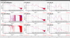
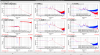
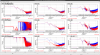
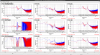
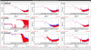
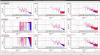
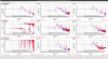
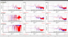
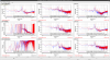
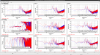
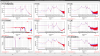
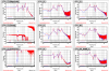
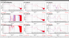
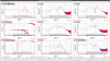
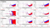
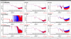
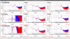
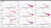
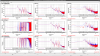
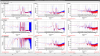
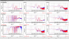
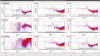
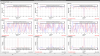
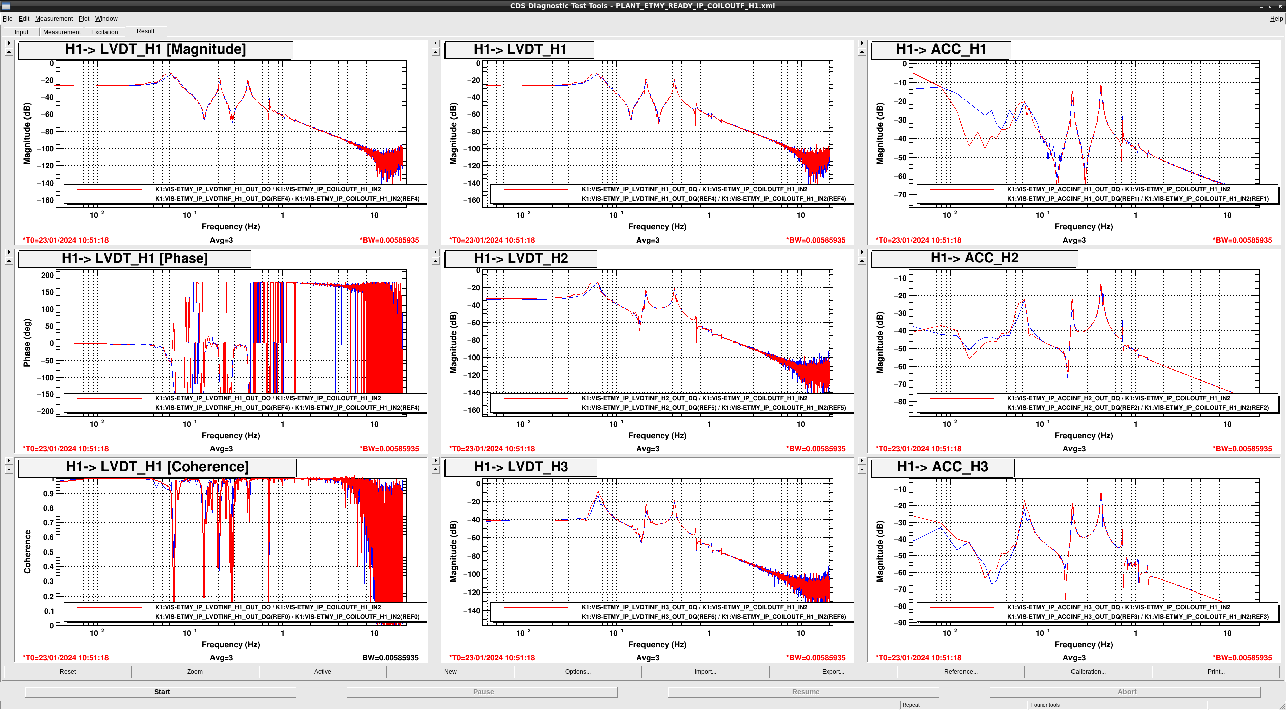
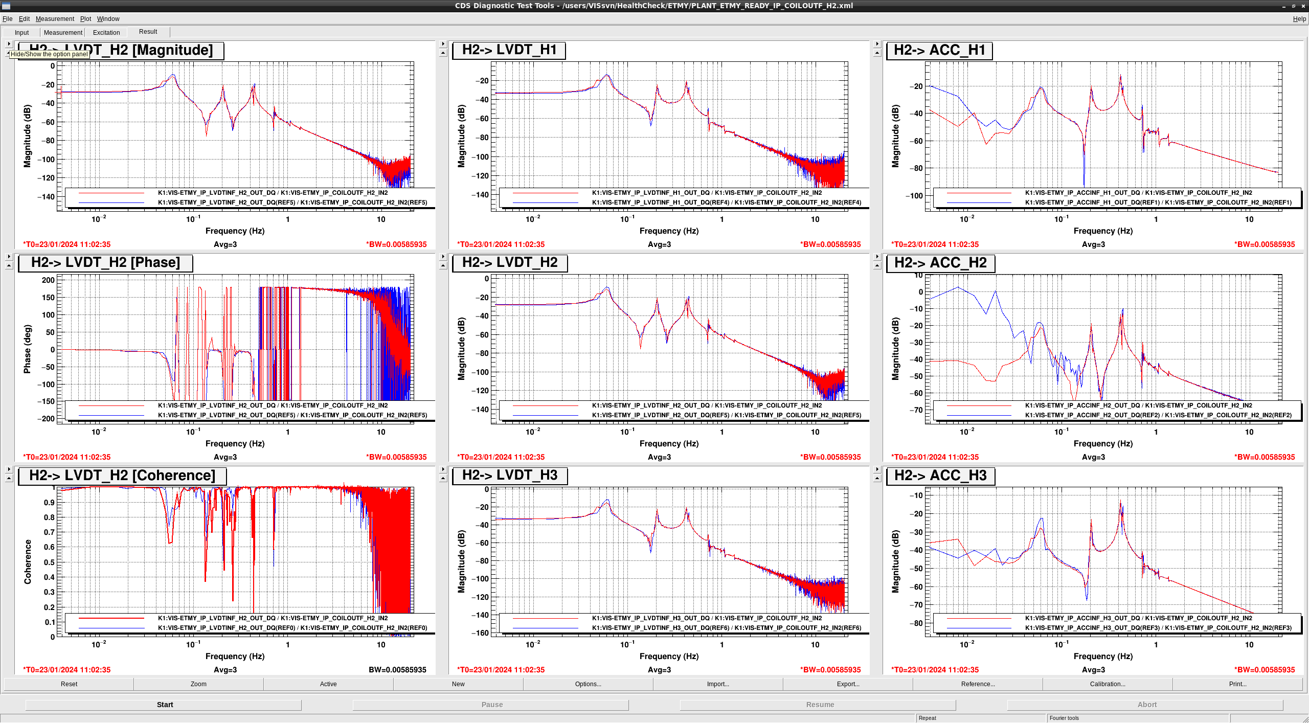
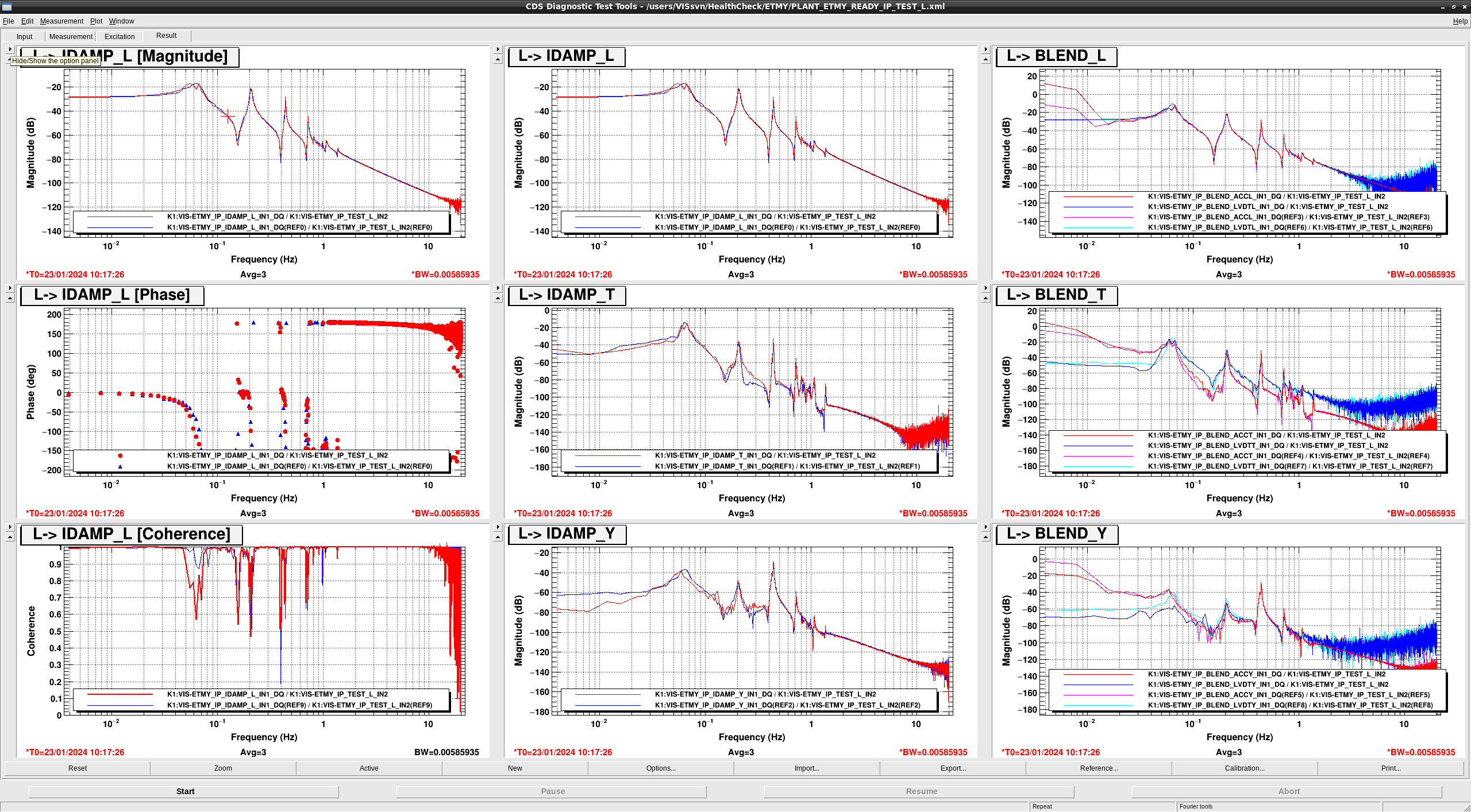
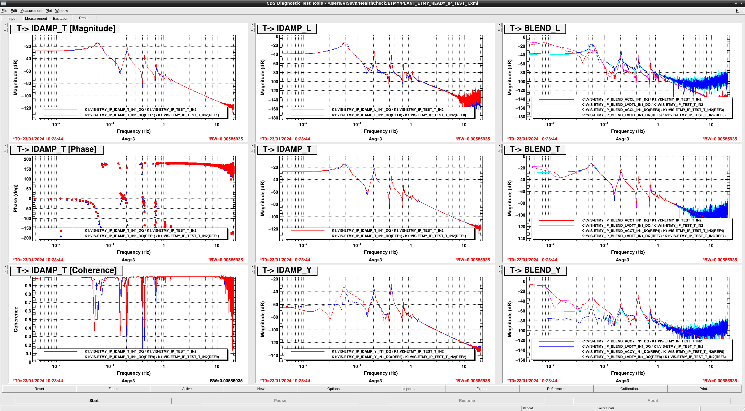
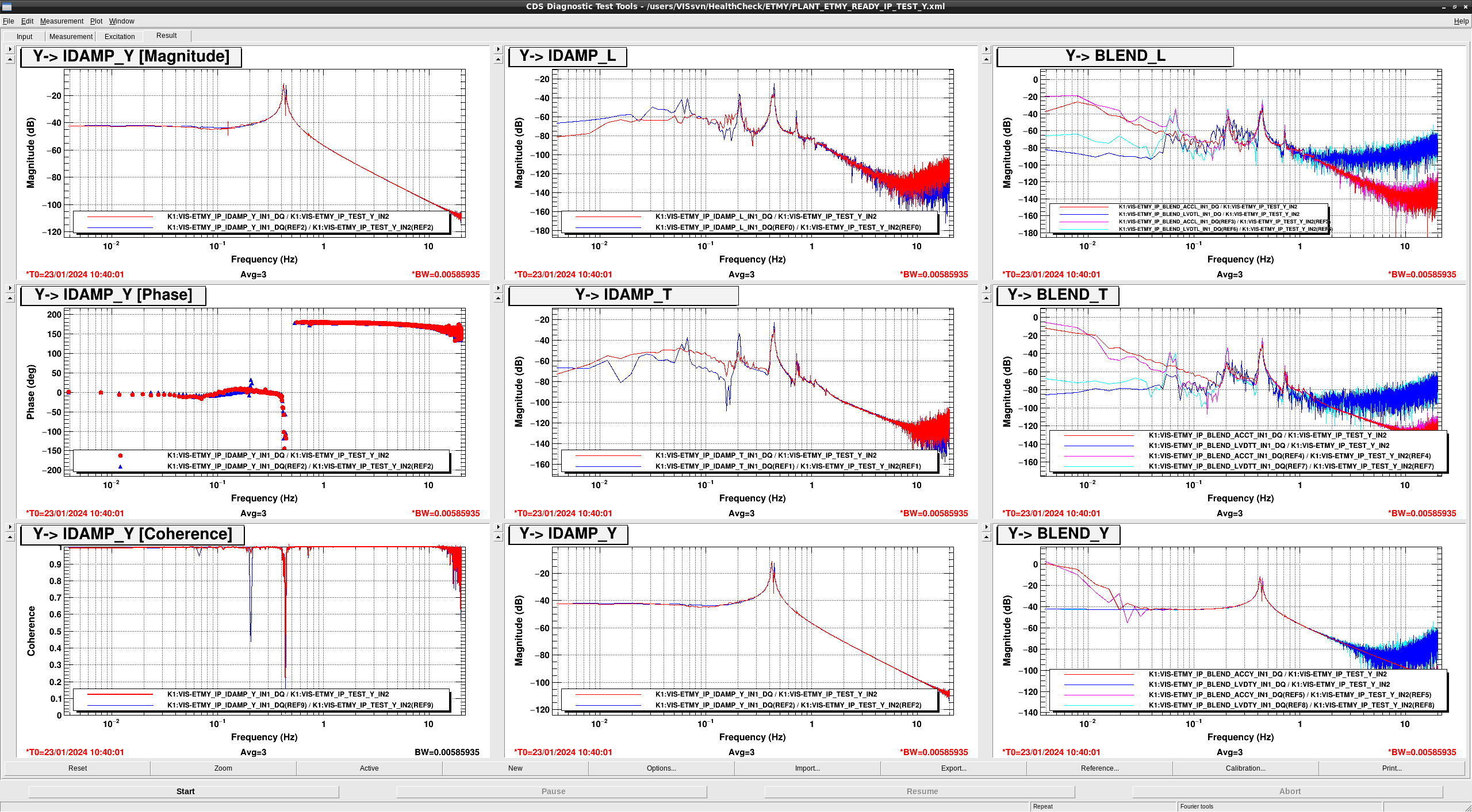
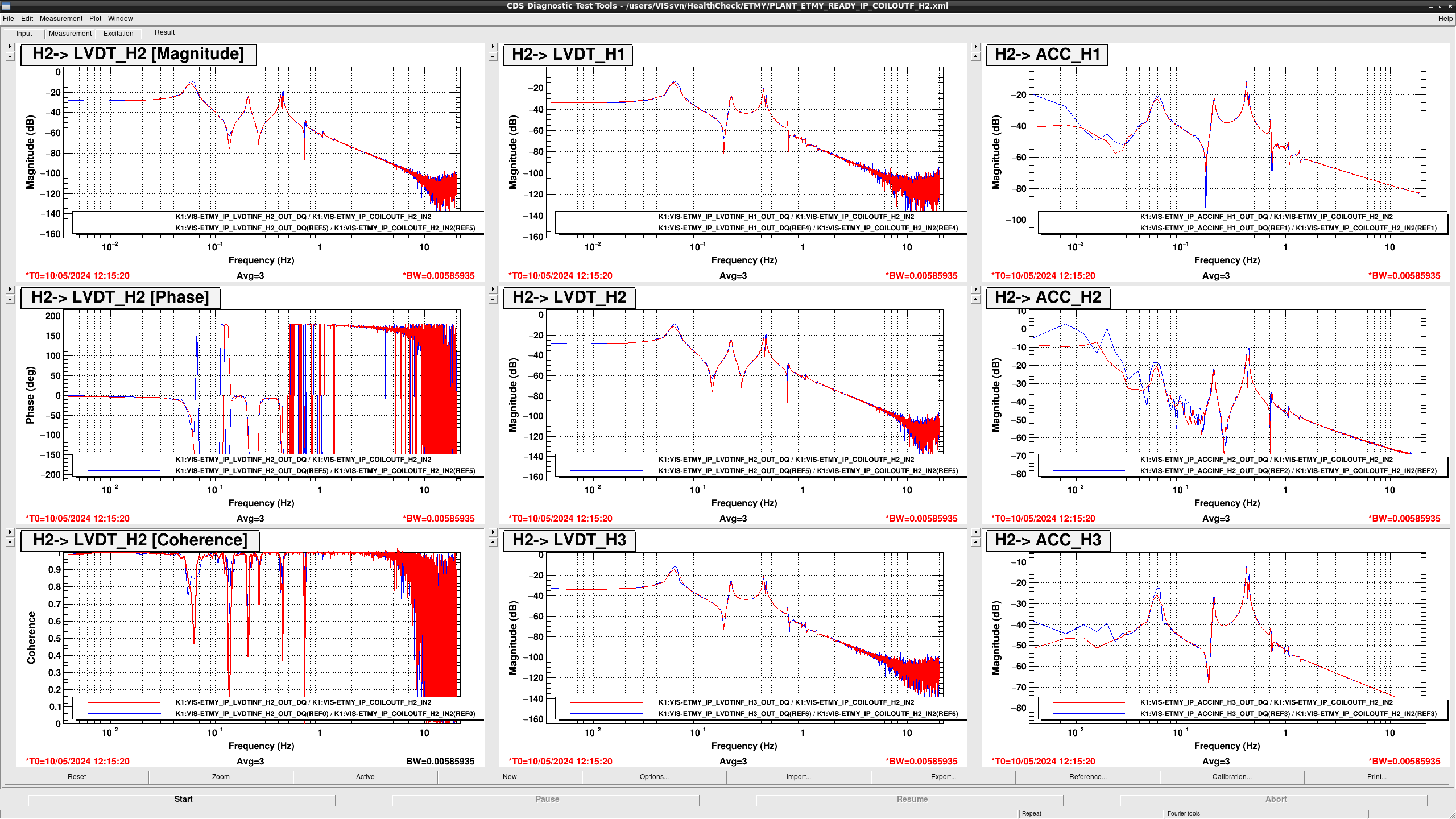
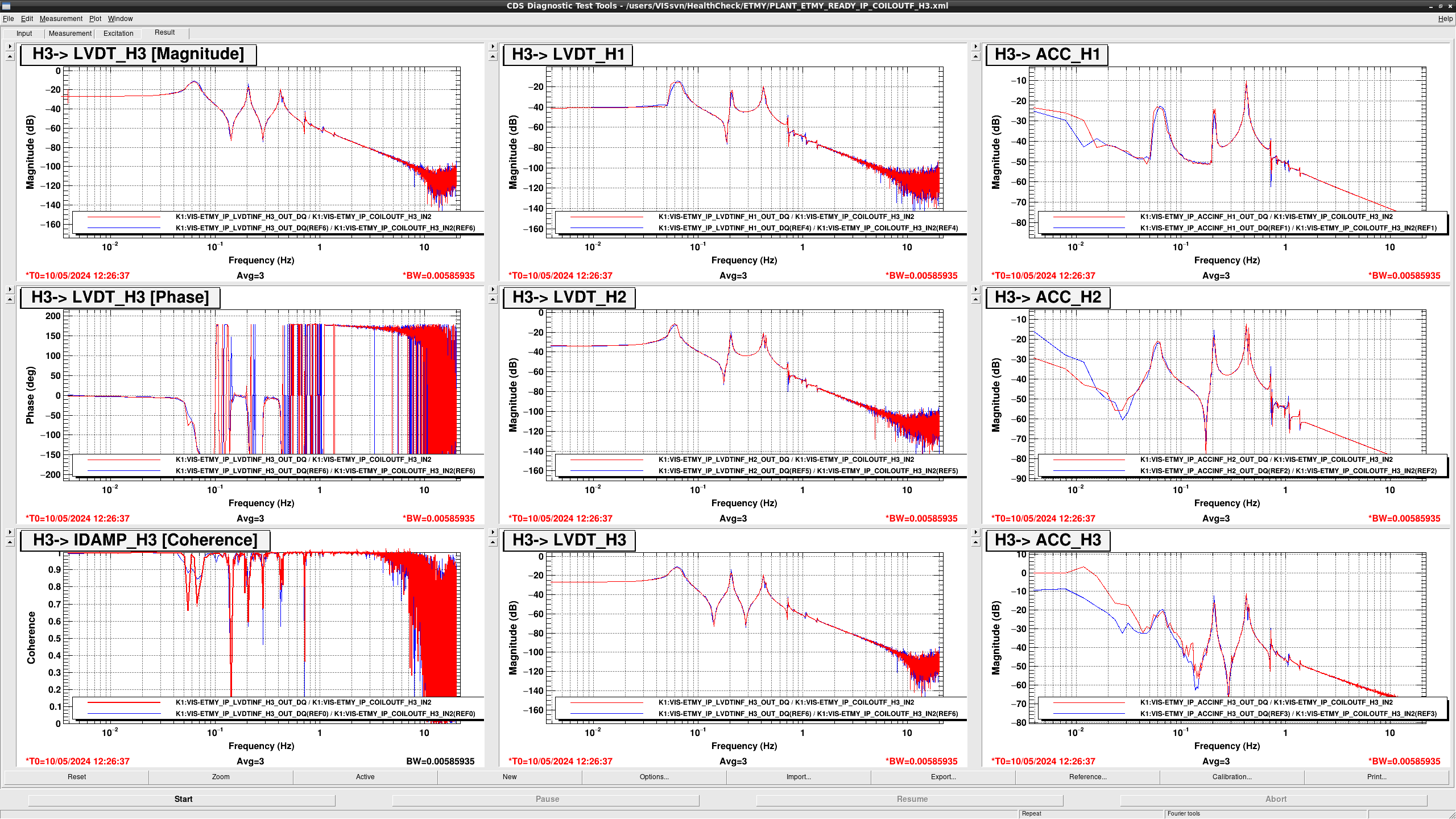
## IP

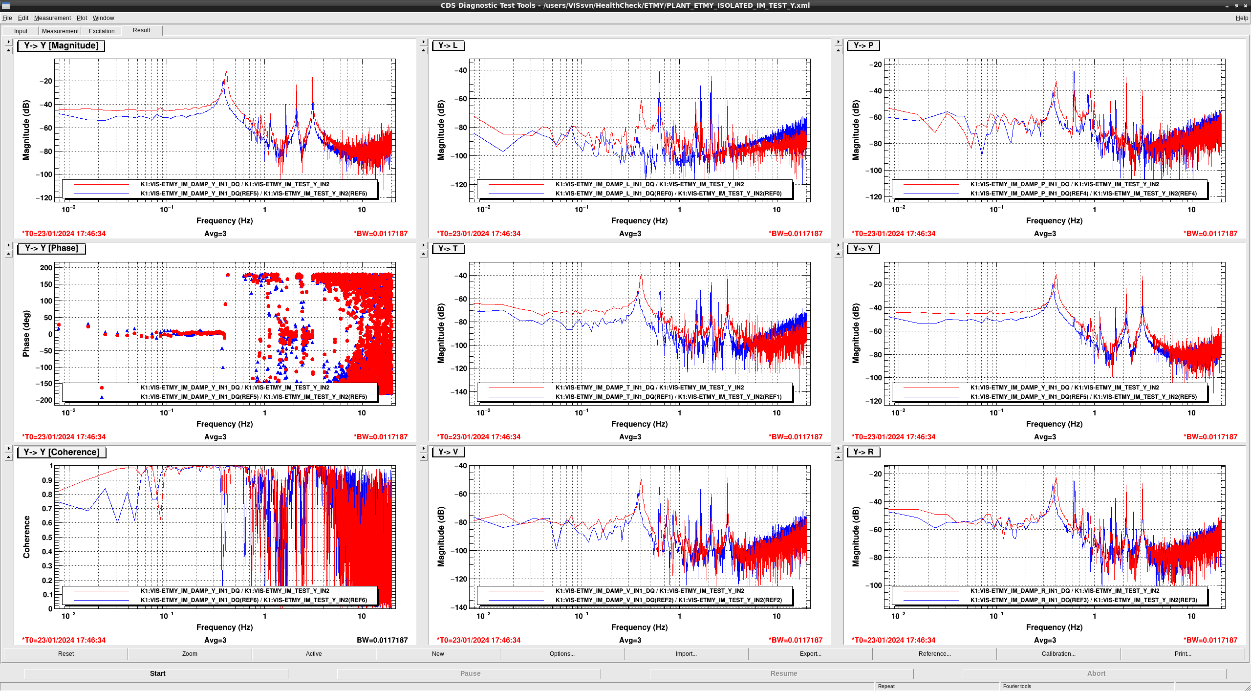
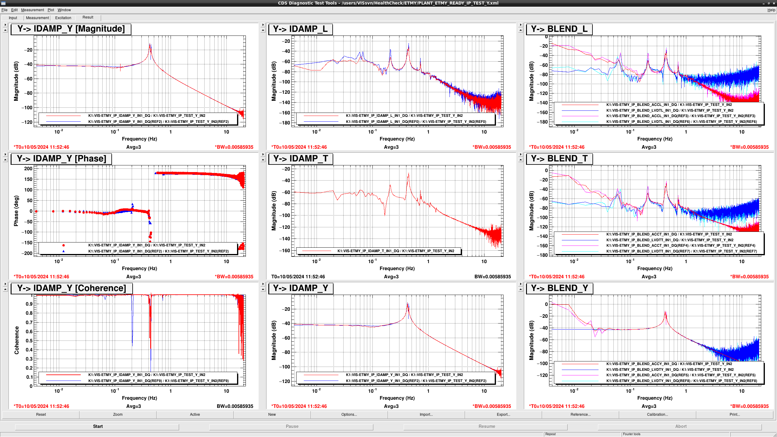
  • The shape below 0.1 Hz in TEST T -> IDAMP Y seems to be changed due to the change of the LVDT Y responce.
  • The shape below 0.2 Hz in TEST Y -> IDAMP L, T seems to be changed.
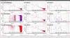
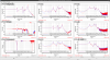
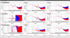
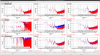
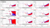
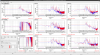
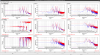
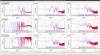
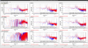
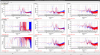
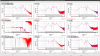
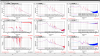
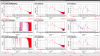
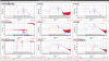
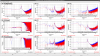
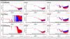
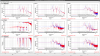
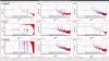
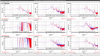
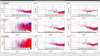
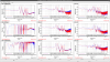
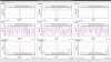
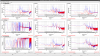
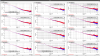
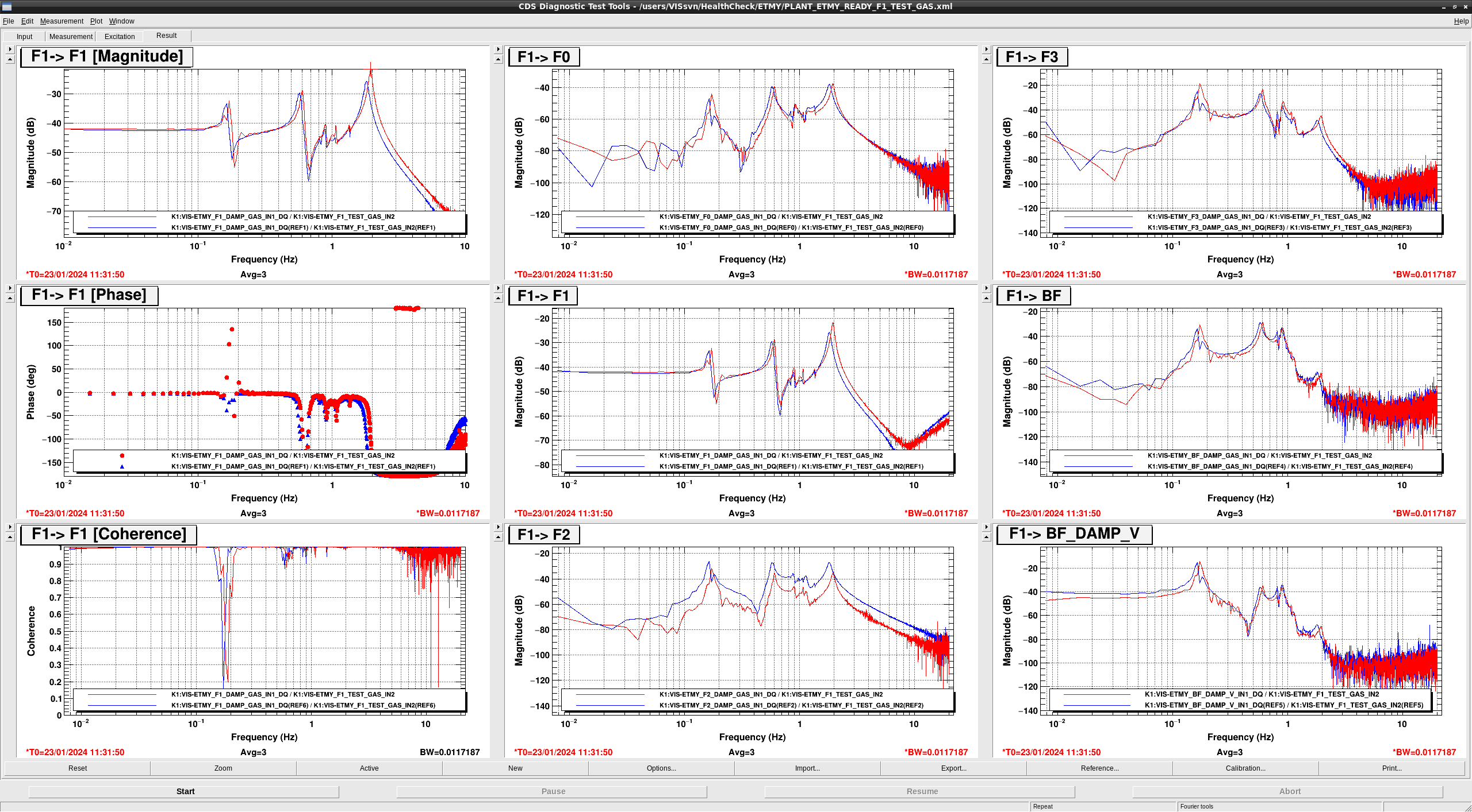
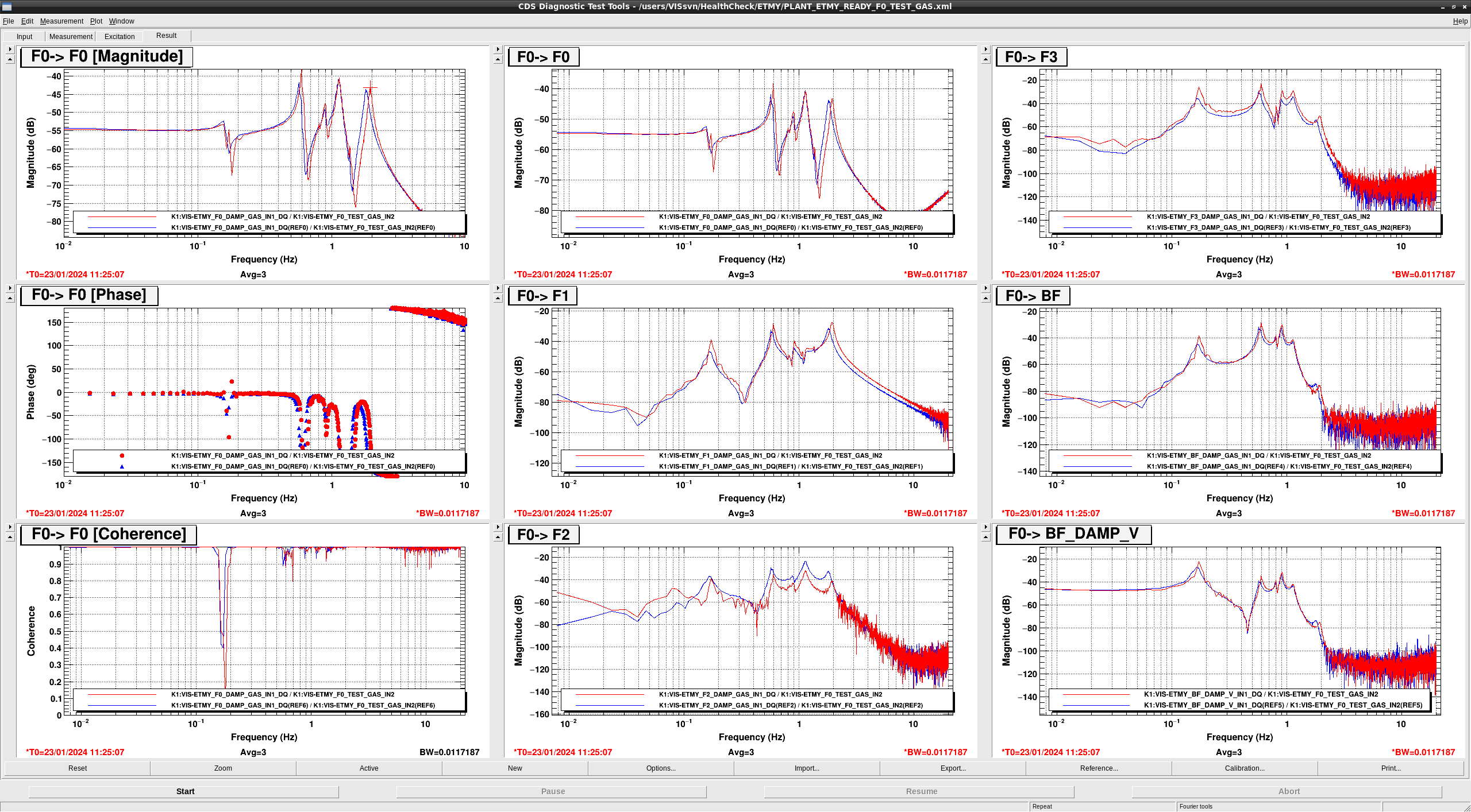
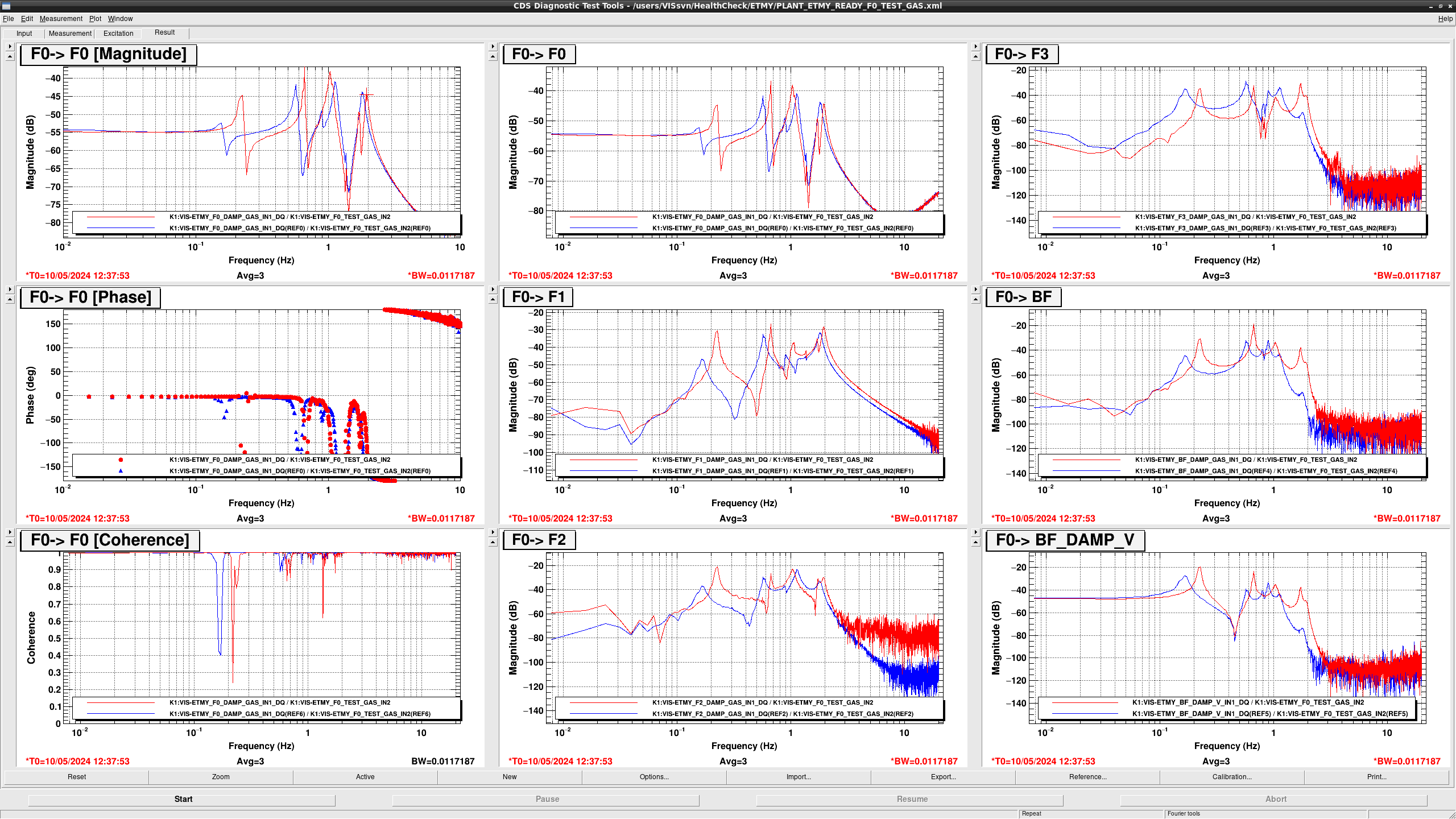
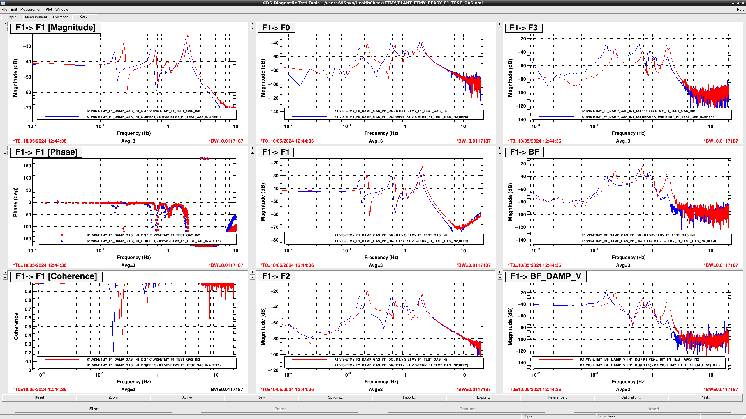
## GAS

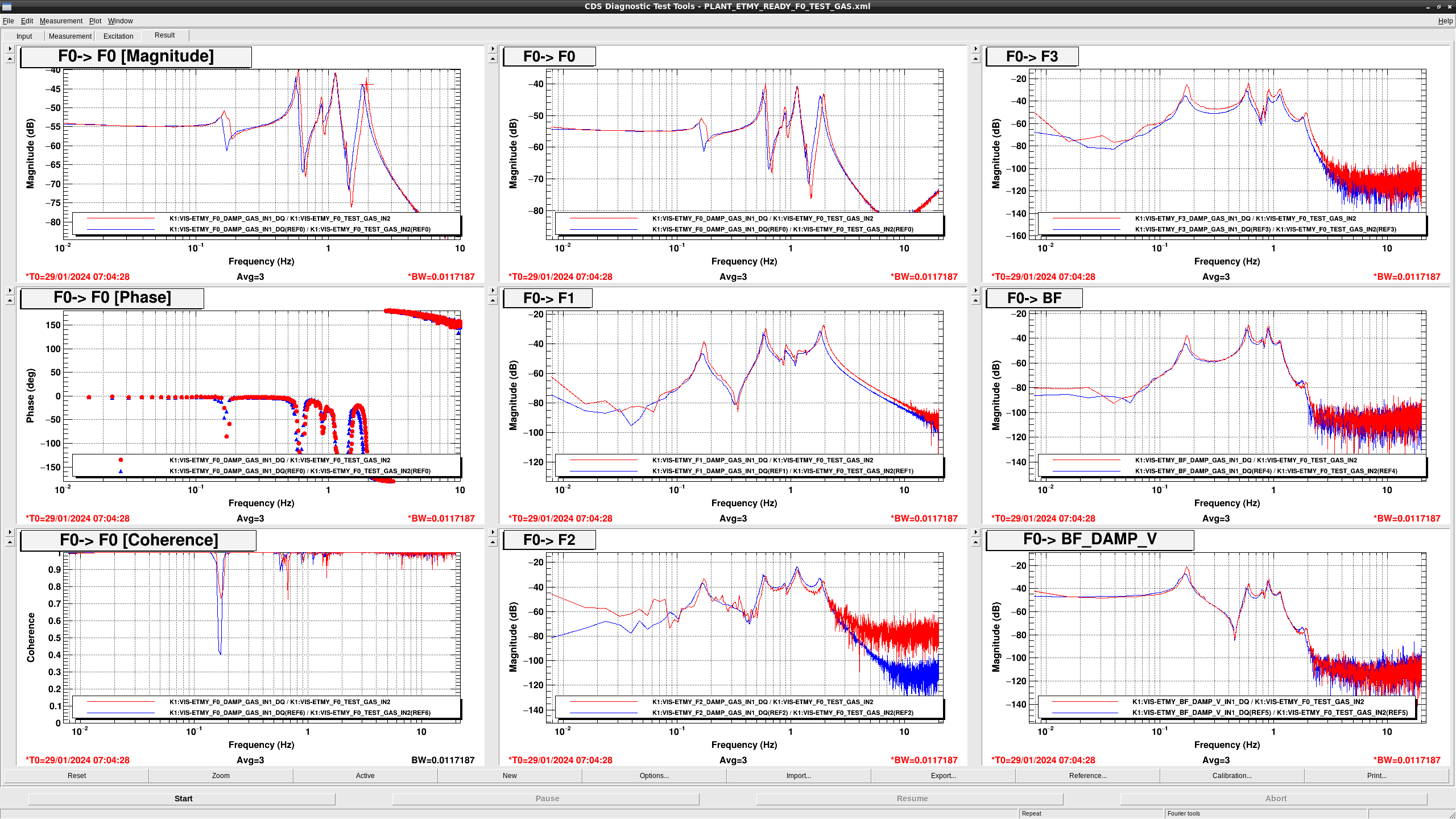
  • in F0 > F0, the resonance peak at 0.57 Hz was shifted to 0.59 Hz and the resonance peak at 1.84 Hz was shifted to 1.95 Hz
  • In F0 > F1 and F3, the overall gains seem to be larger slightly.
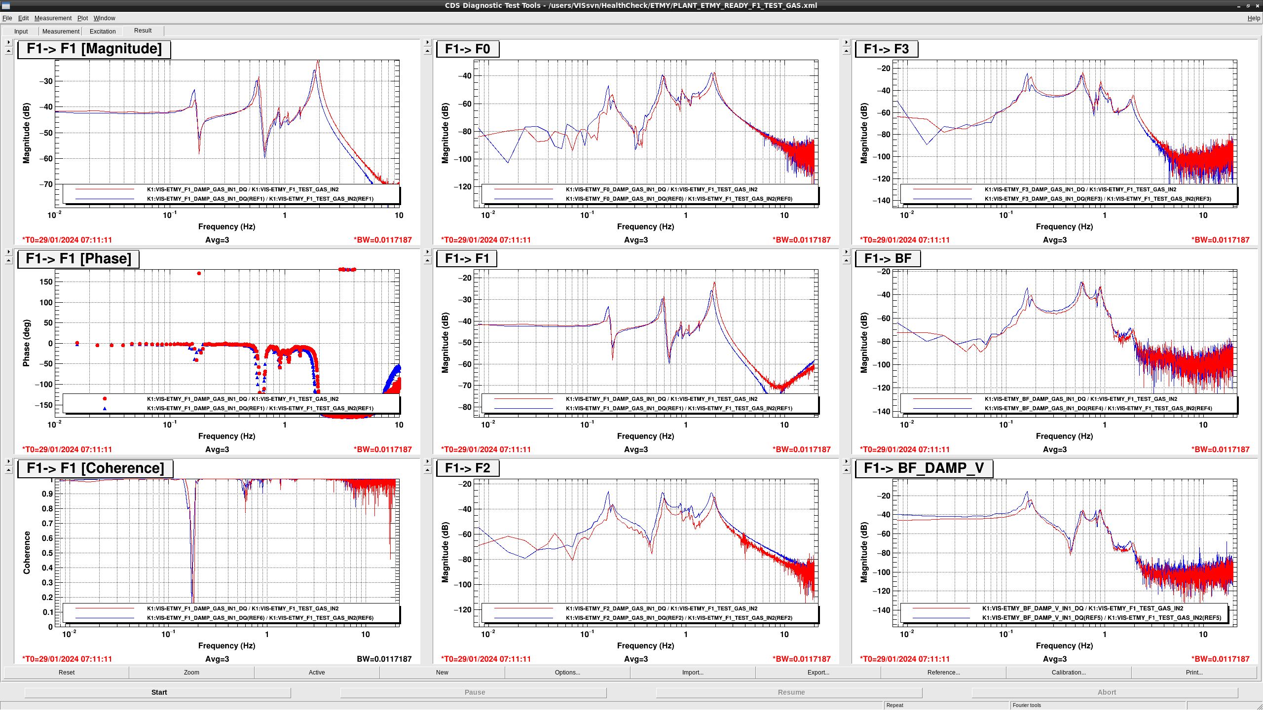
  • In F1 > F1, the resonance peak at 0.164 Hz was shifted to 0.172 Hz, the resonance peak at 0.578 Hz was shifted to 0.602 Hz, and the resonance peak at 1.81 Hz was shifted to 1.95 Hz
  • In F1 > {F0, F3, BF}, all of the resonant frequencies got higher slightly.
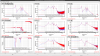
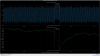
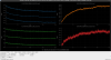
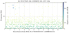
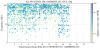
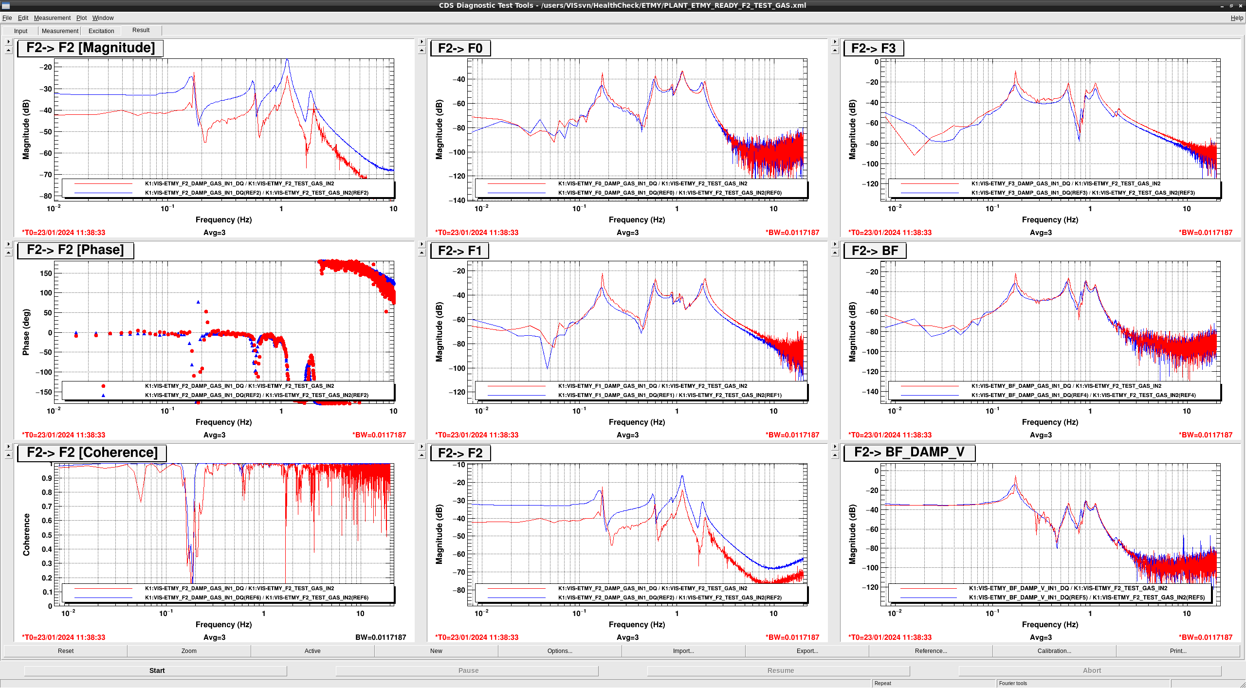
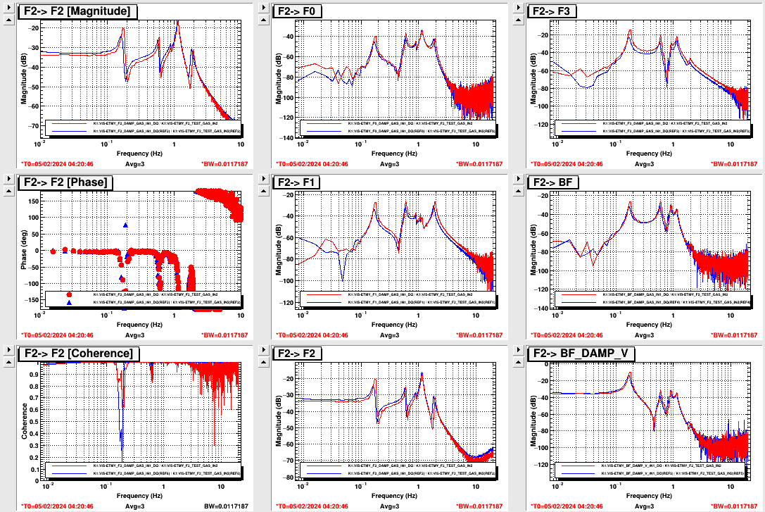
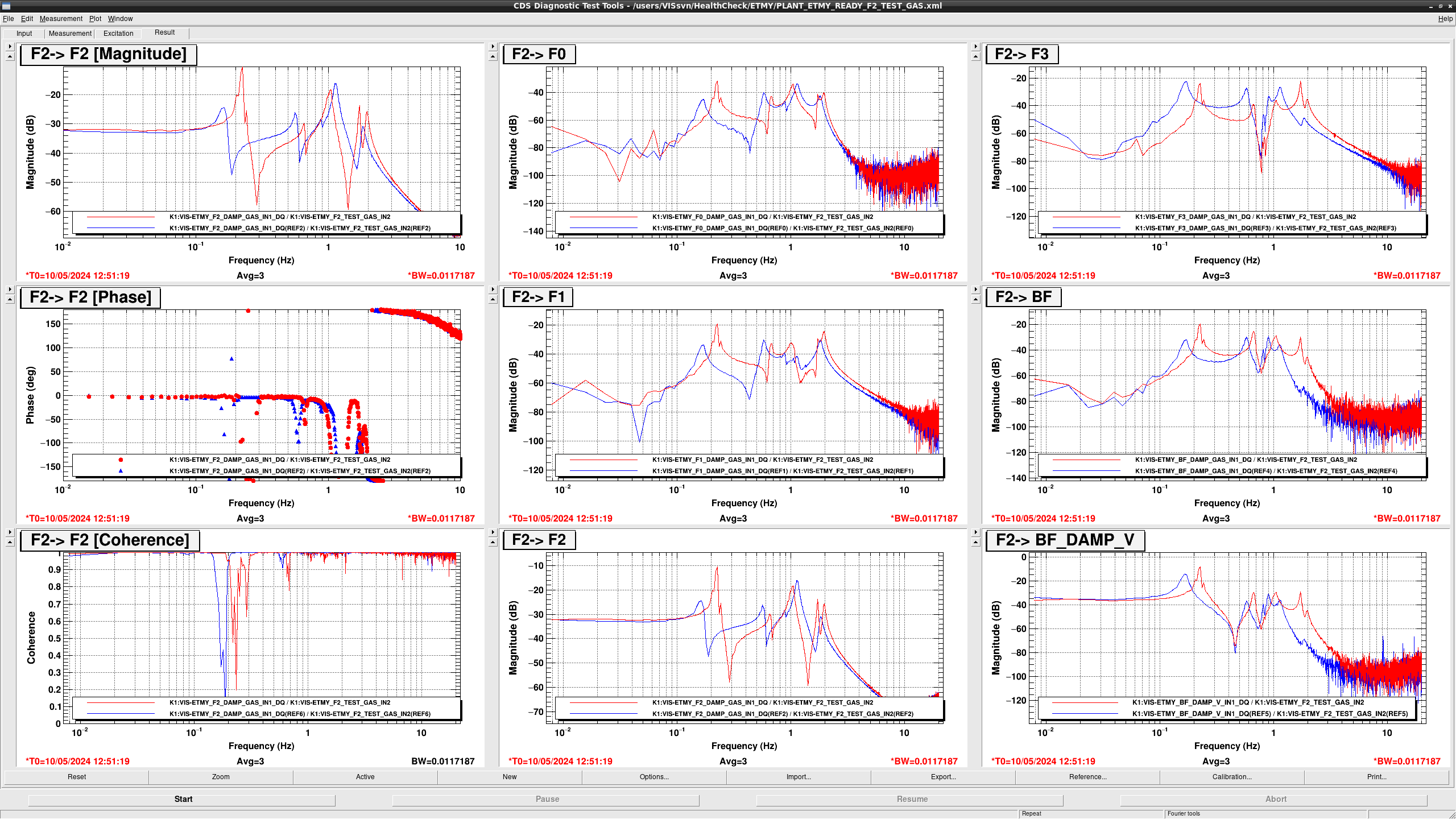
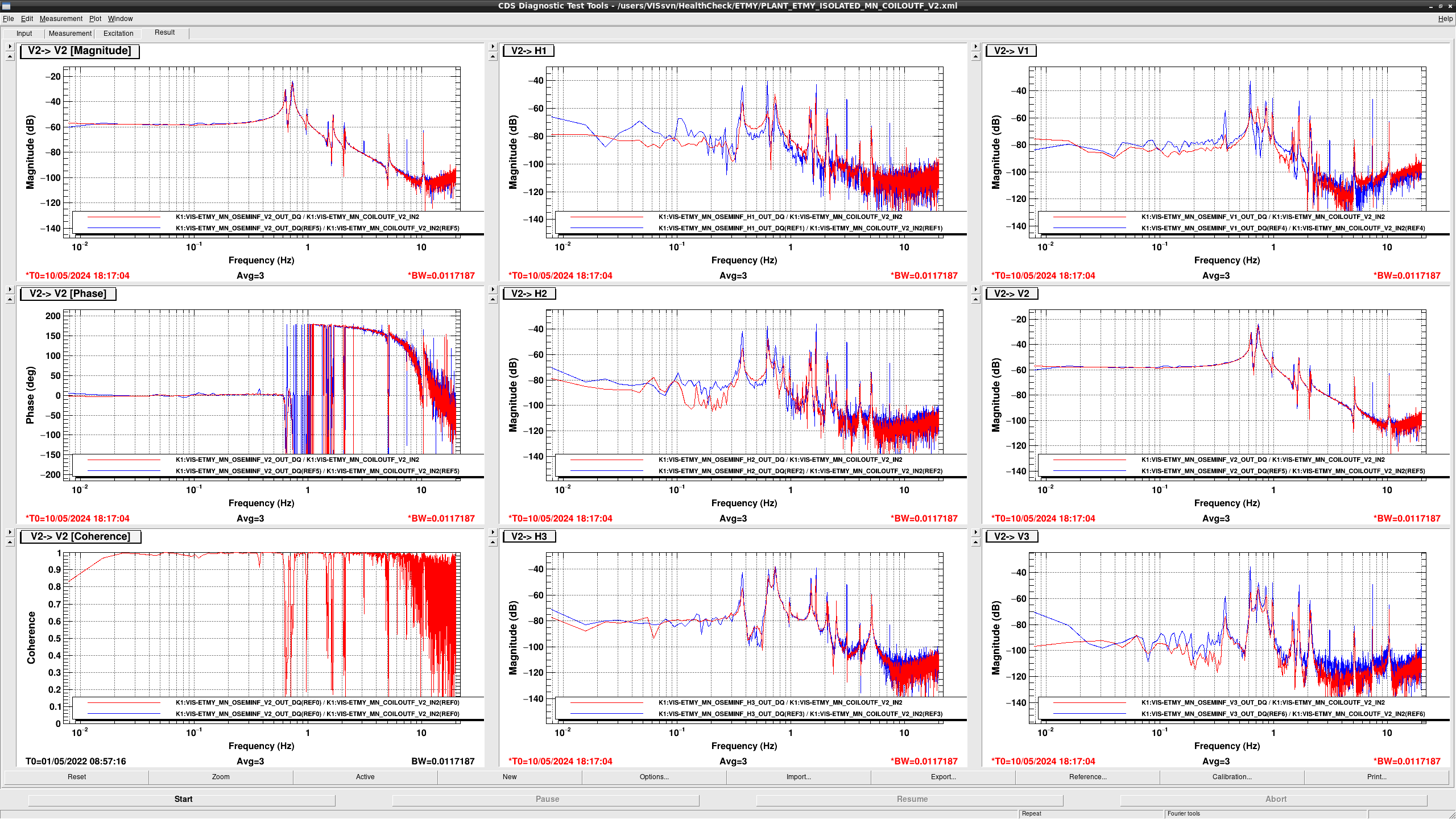
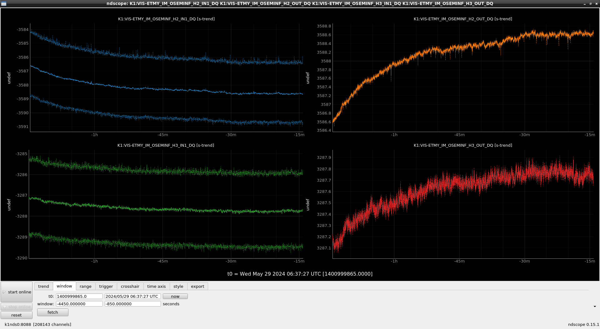
  • In F2 > F2 and the other GASs > F2, the overall gain seems to be smaller to -10dB. The F2 GAS LVDT signal (K1:VIS-ETMY_F2_LVDTINF_GAS_INMON) in the STANDBY state is over 10000 cnts, This shows the standby position is out of the linear range (+/- 10000) according to Dropbox acceptance paper.
  • In F2 > F2, The resonance peak at 0.164 Hz shifted to 0.172 Hz, the resonance peak at 0.578 Hz shifted to 0.594 Hz, and the resonance peak at 1.84 Hz  shifted to 1.95 Hz
  • In F2 > {F0, F1, F3, BF}, all of the overall gains and the resonant frequencies got larger and higher slightly.
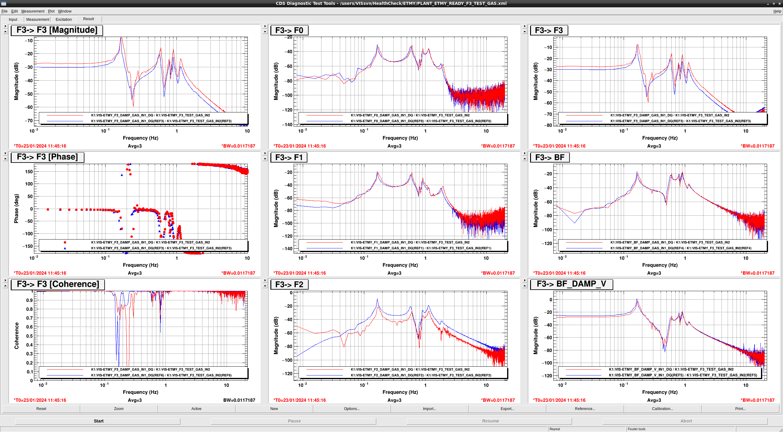
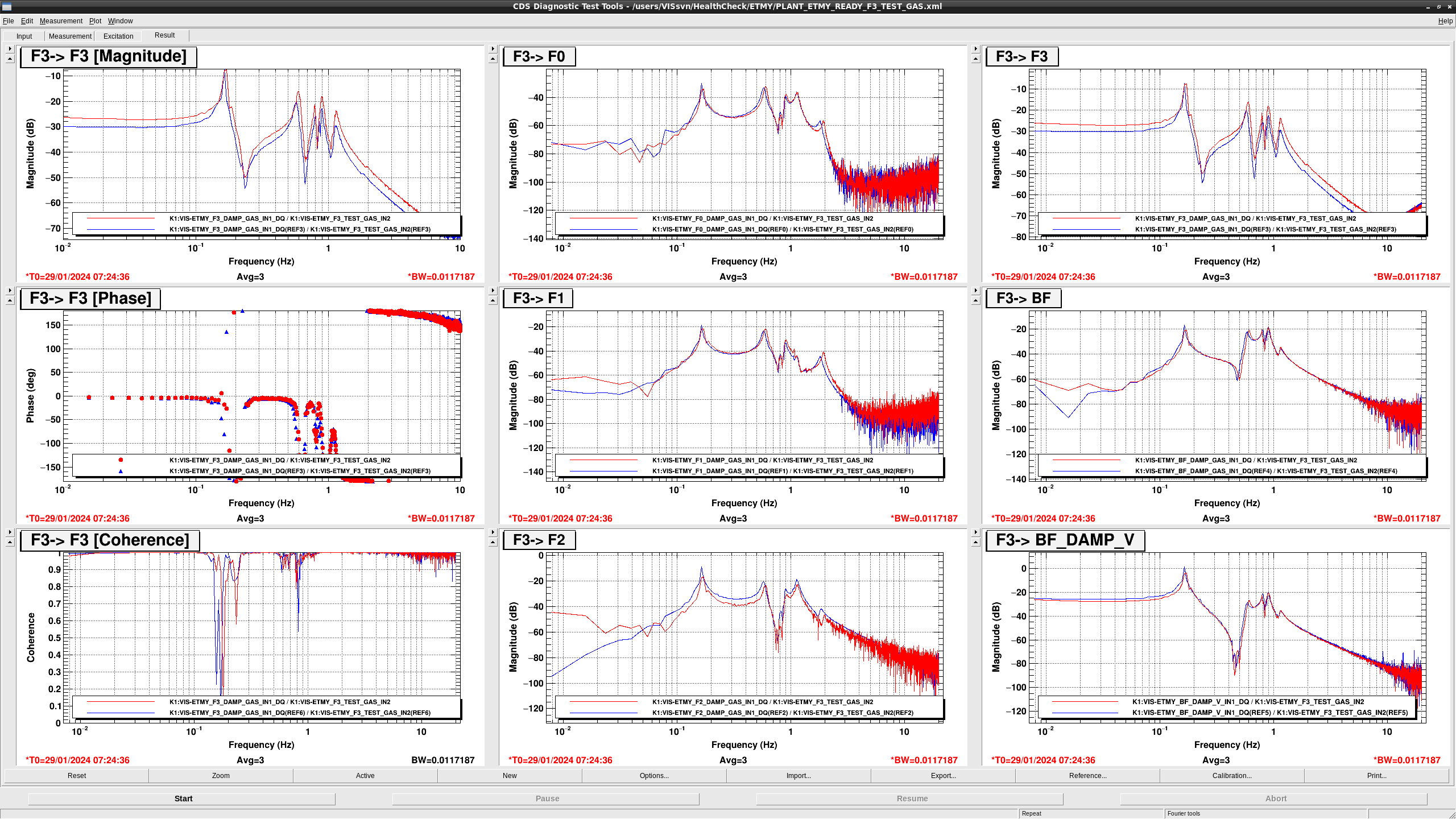
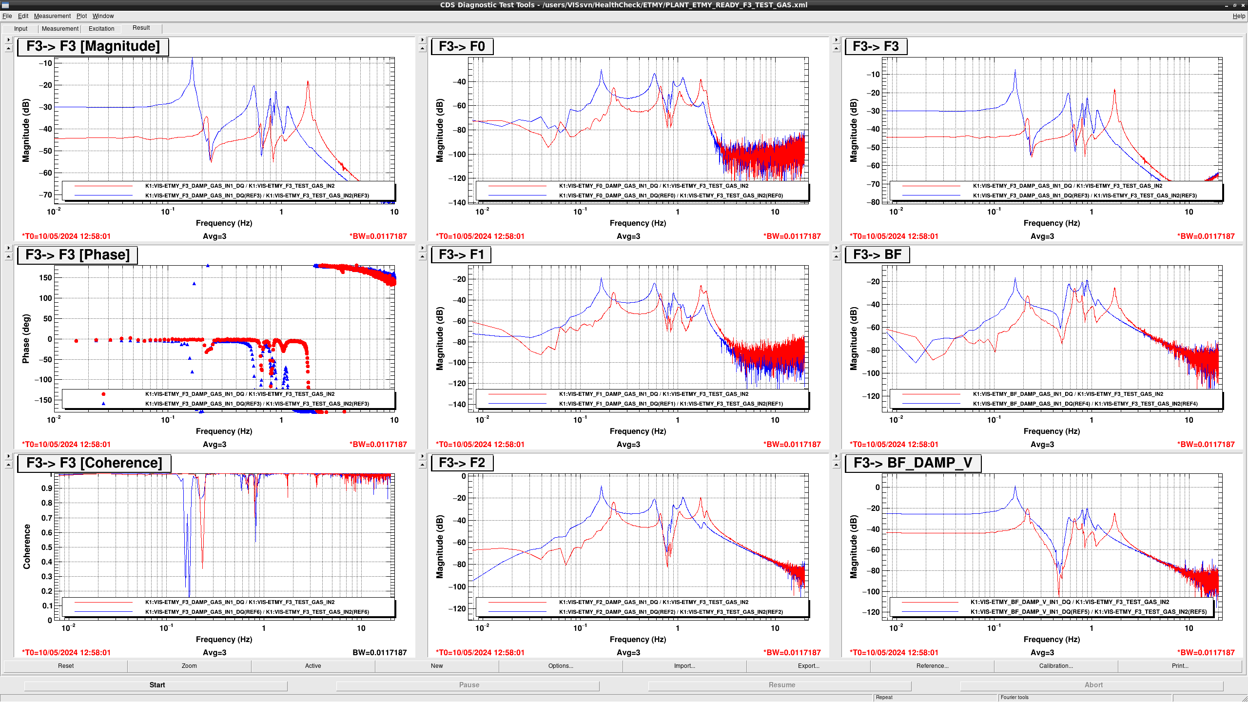
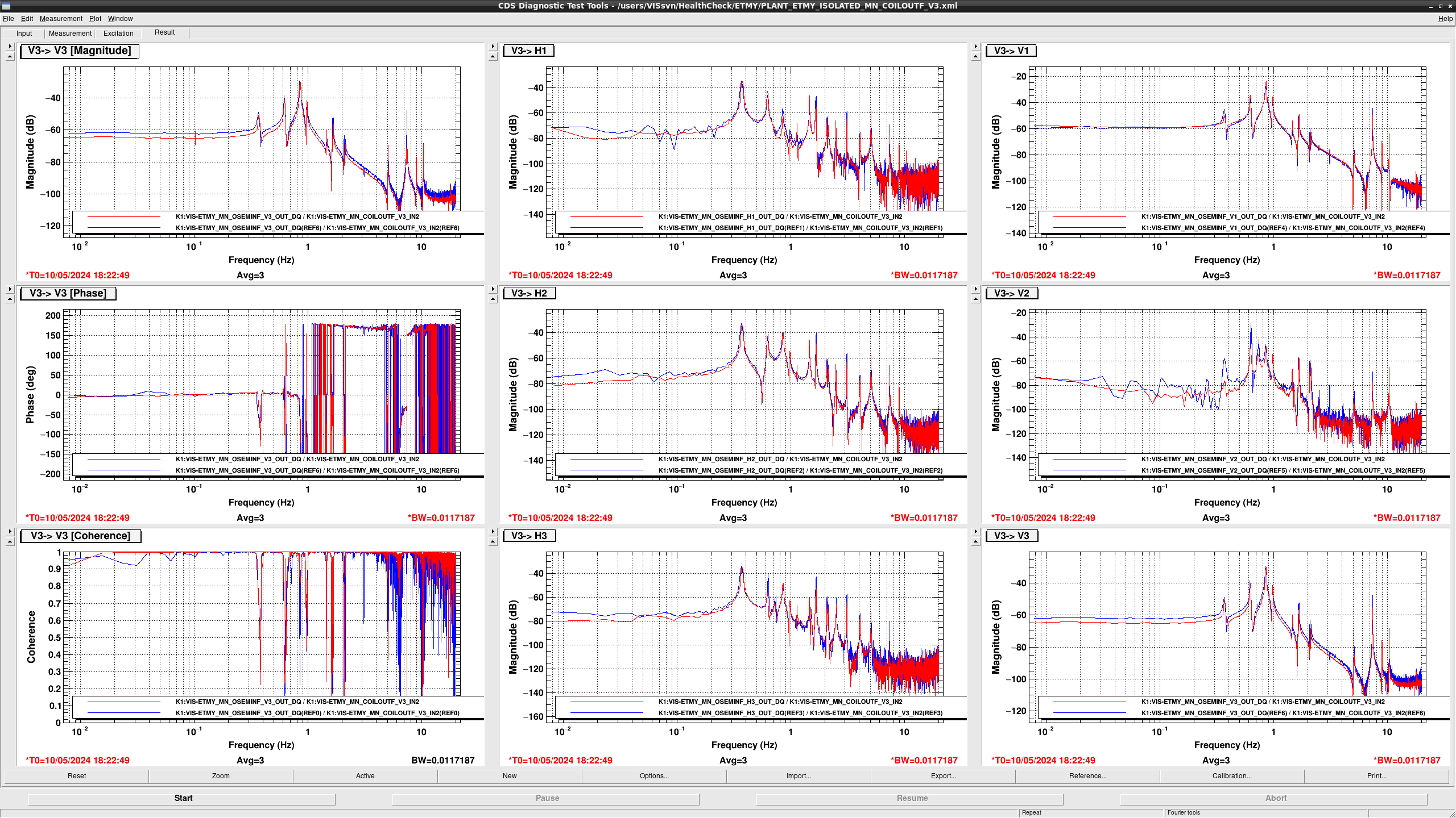
  • In F3 > F3, the overall gain gat larger to +6dB.
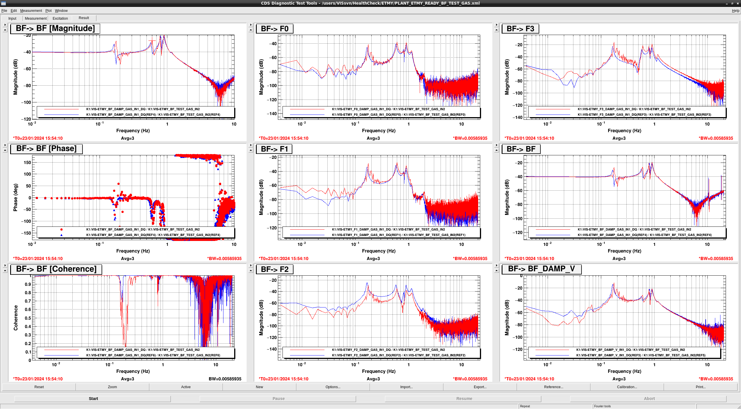
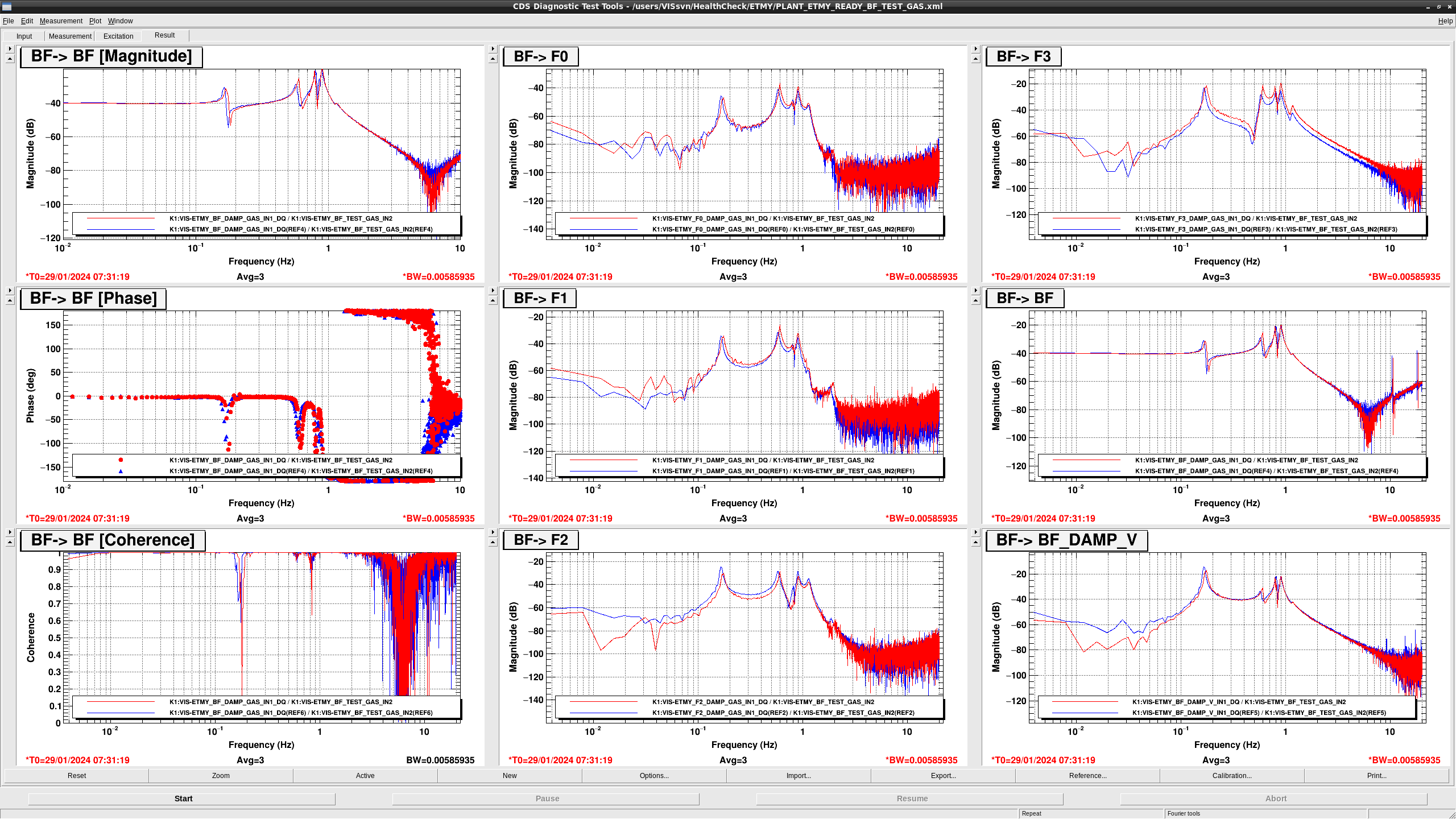
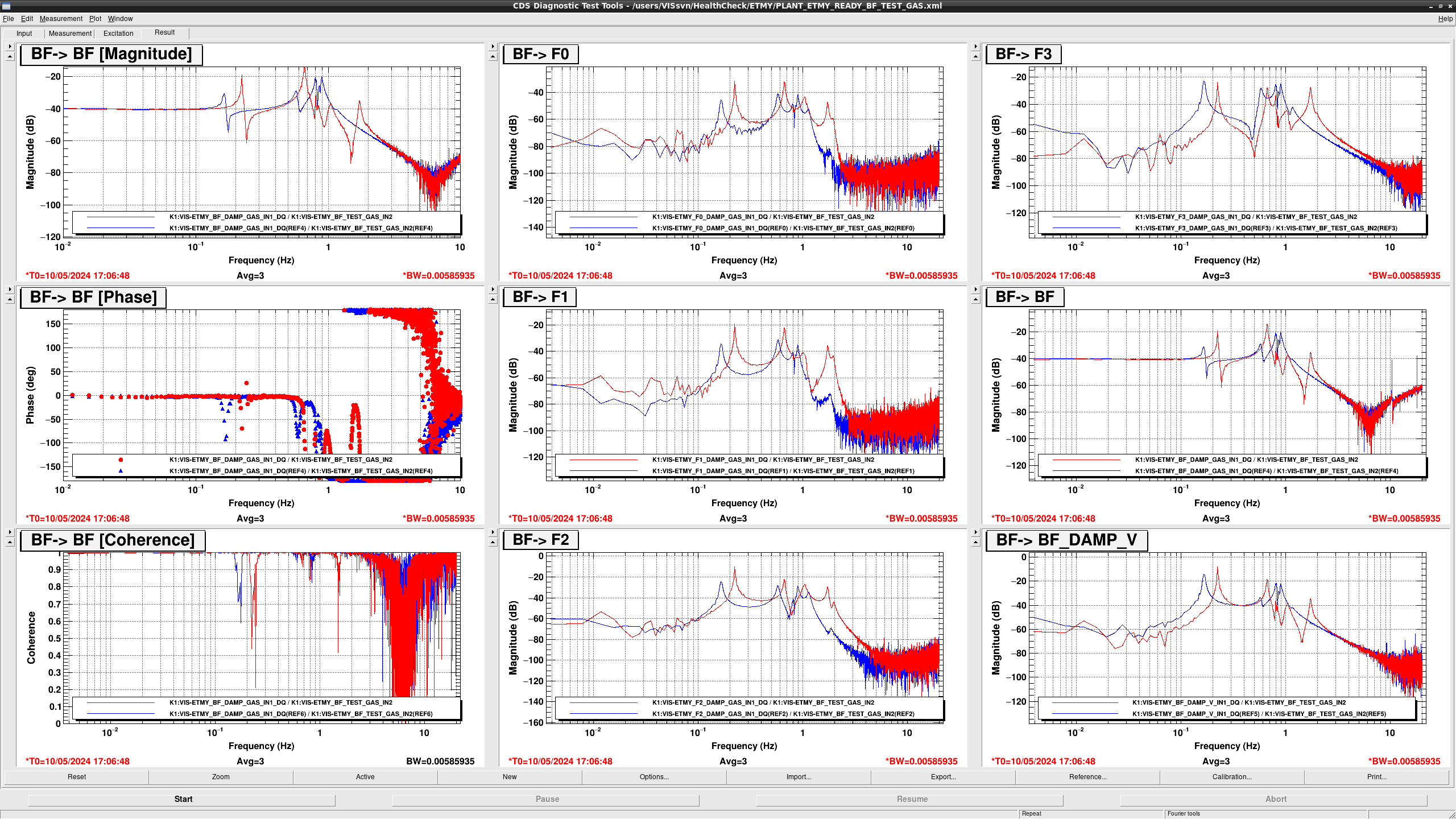
  • In BF > BF, the resonance peak at 0.164 Hz shifted to 0.175 Hz, and the resonance peak at 0.574 Hz  shifted to 0.602 Hz.
  • In BF > {F0, F1, F3}, all of the overall gains and the resonant frequencies got larger and higher slightly.
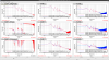
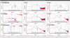
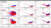
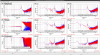
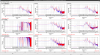
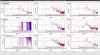
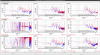
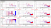
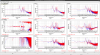
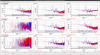
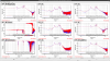
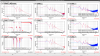
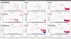
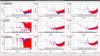
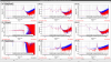
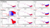
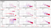
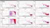
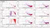
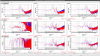
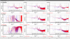
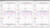
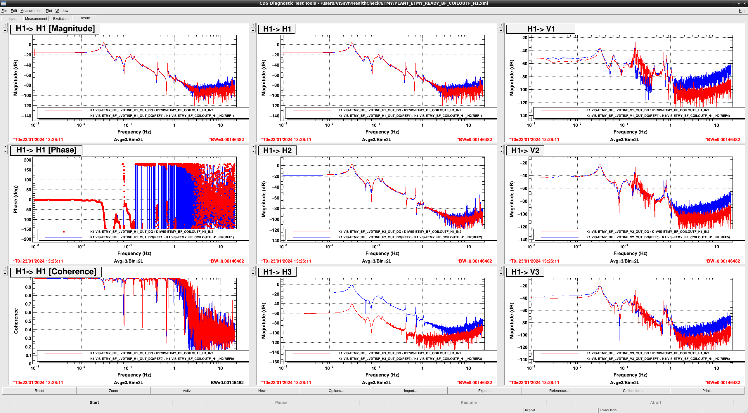
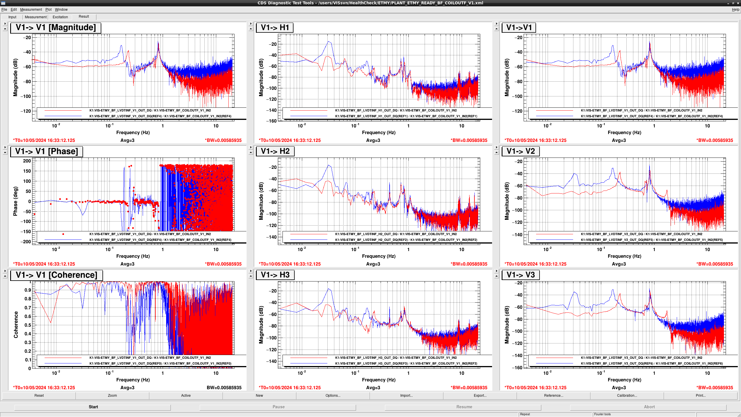
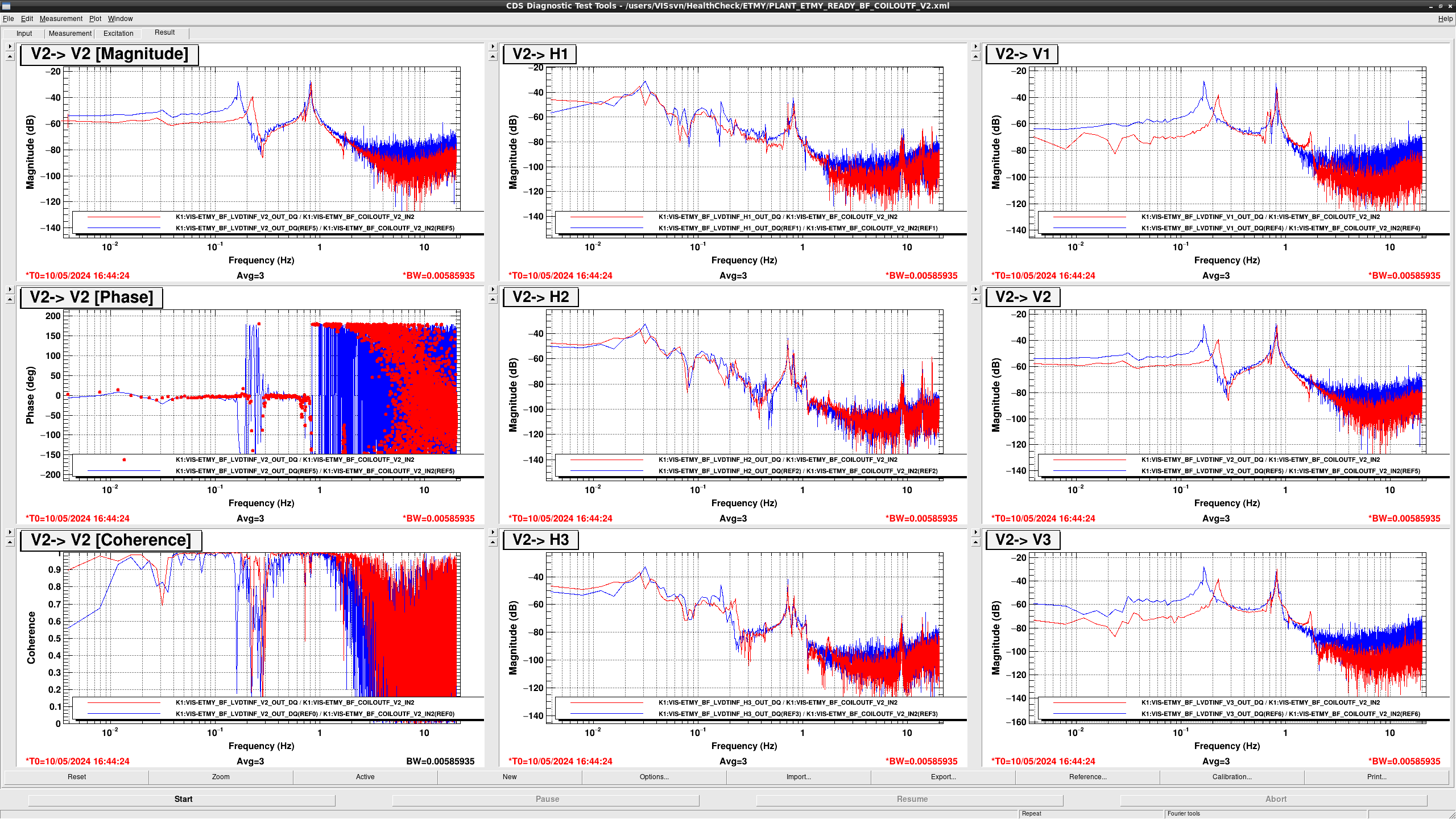
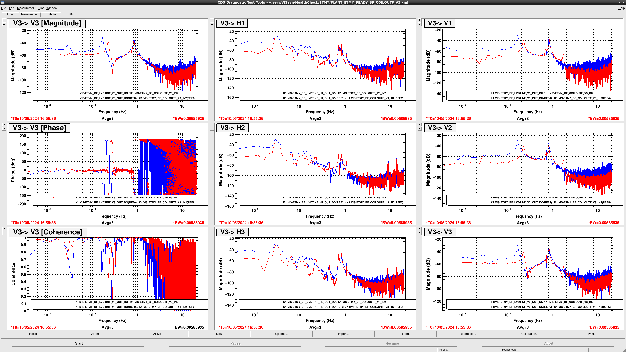
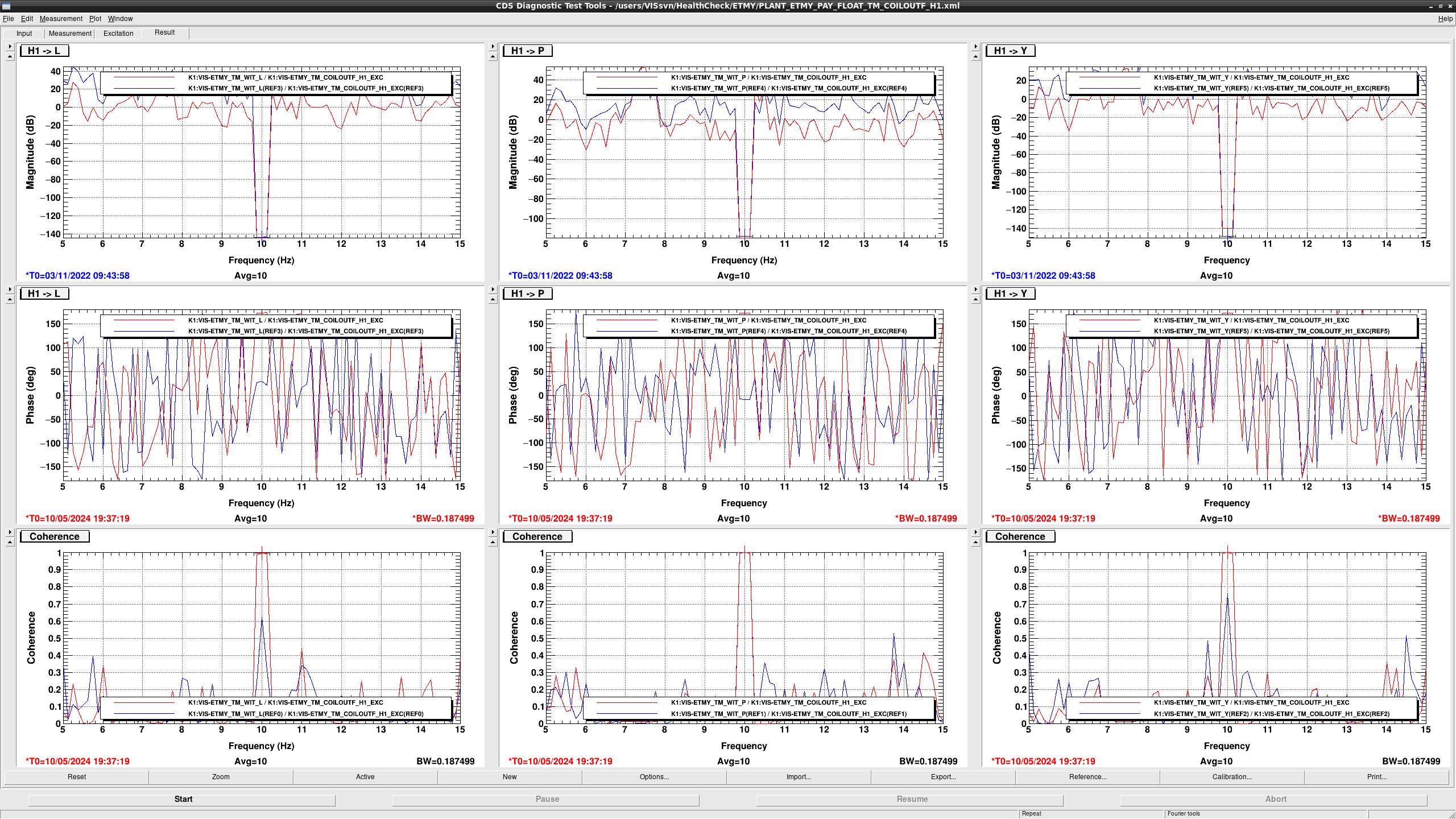
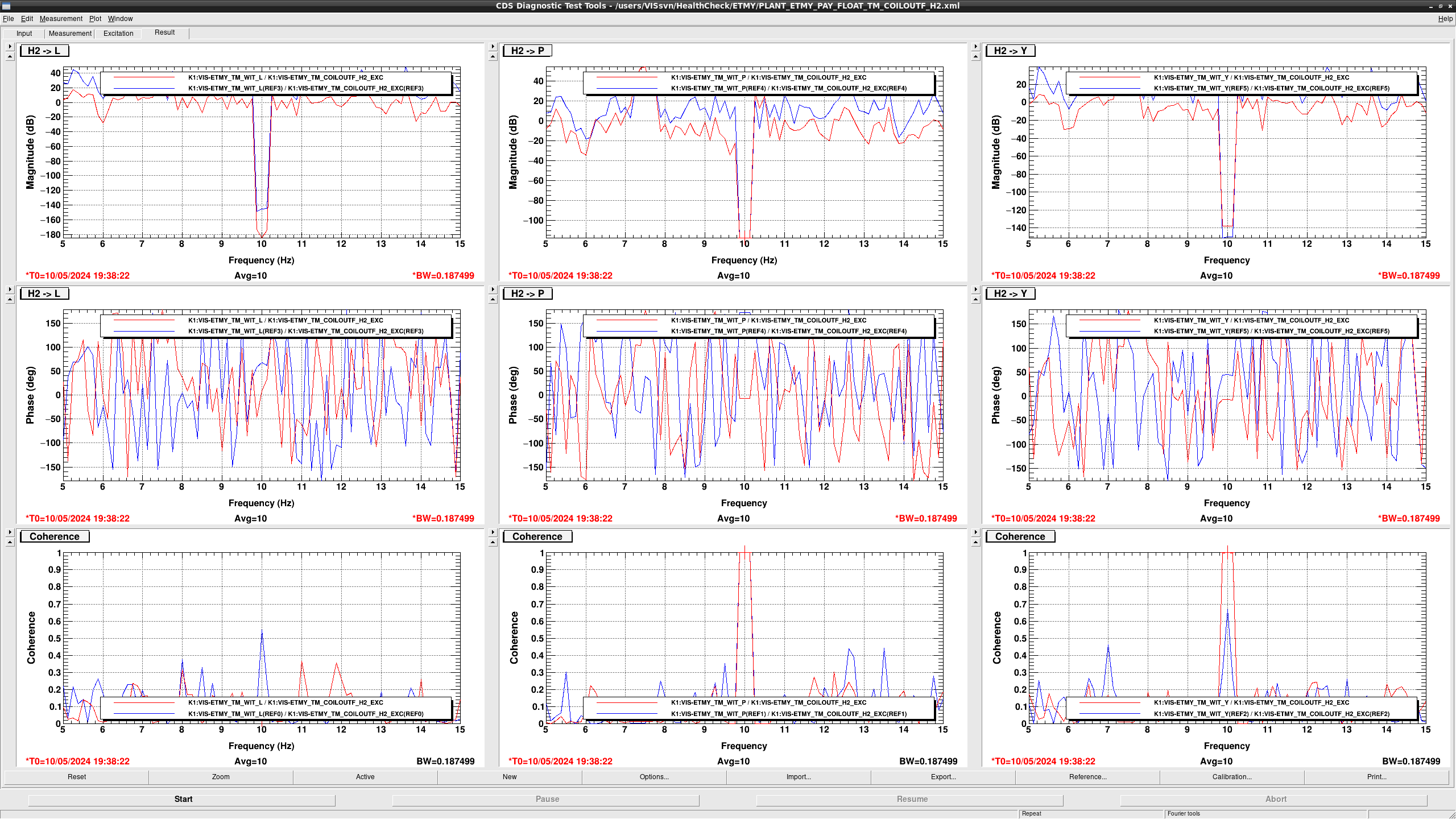
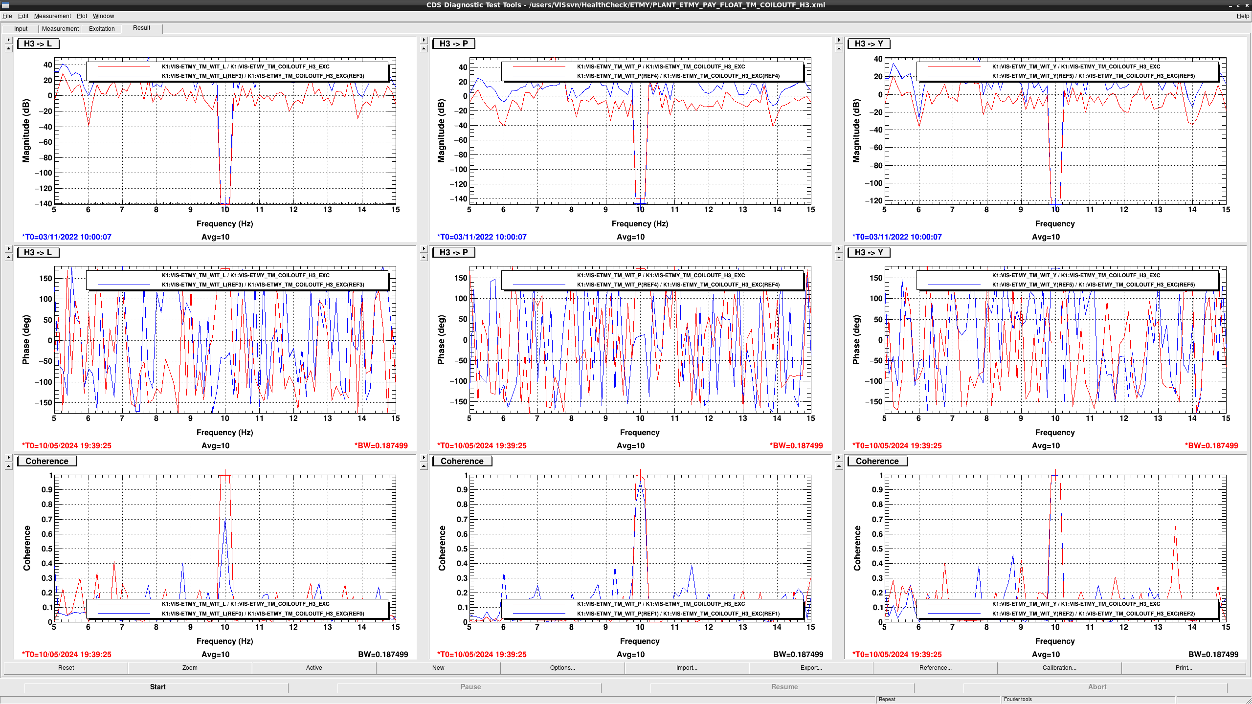
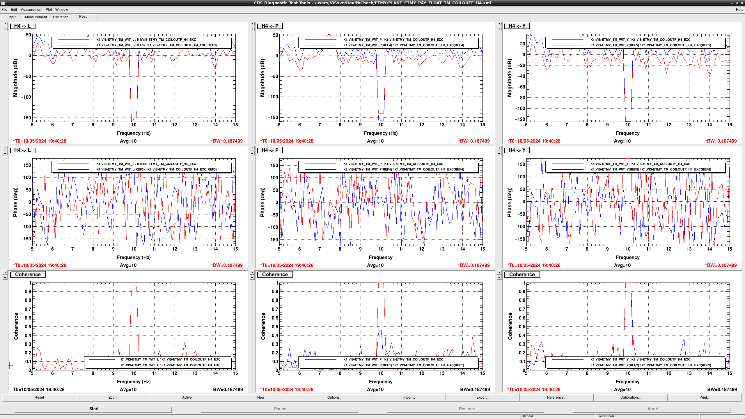
## BF

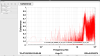
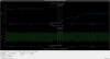
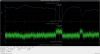
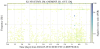
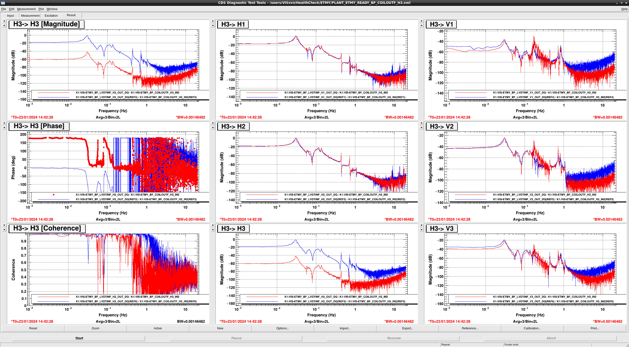
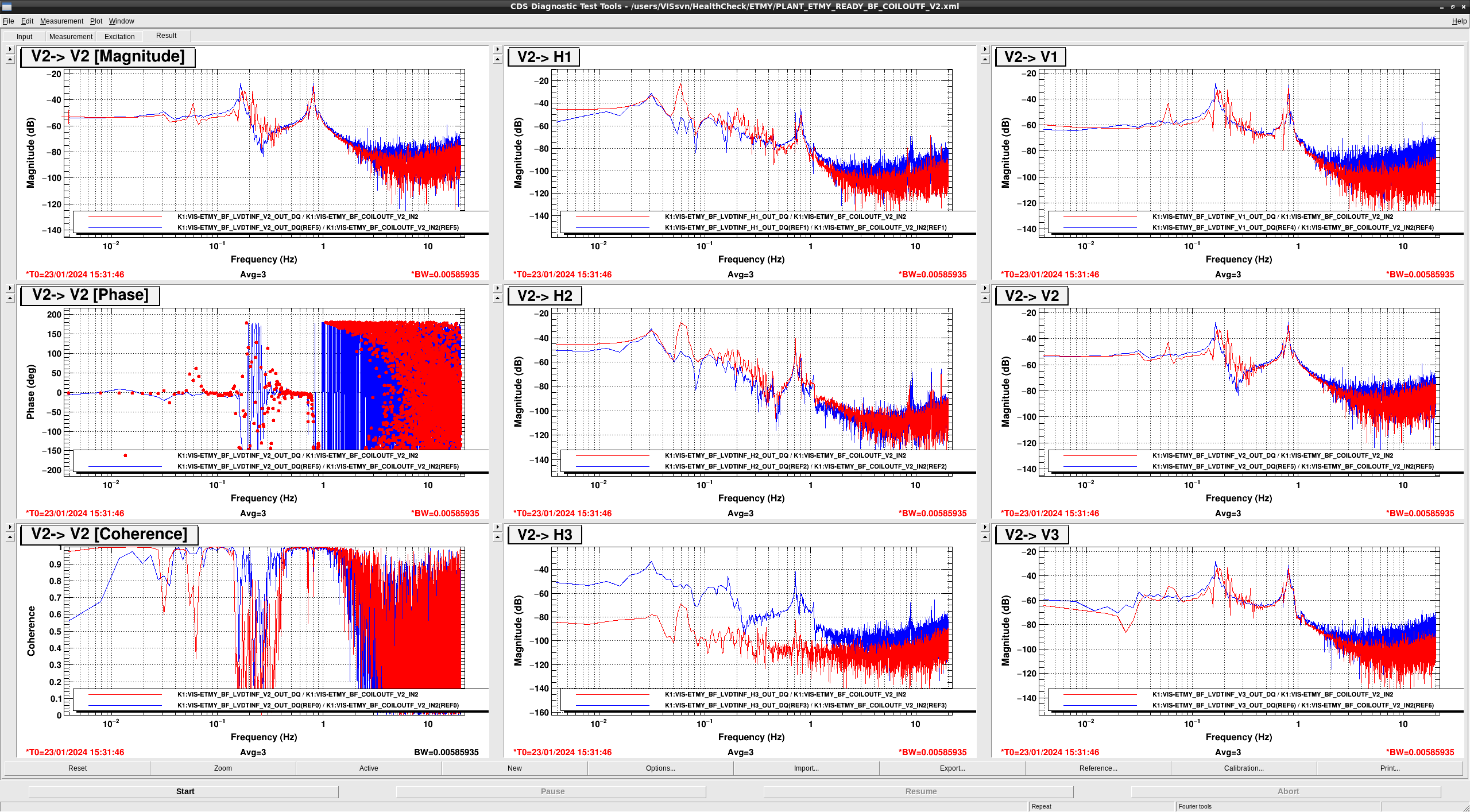
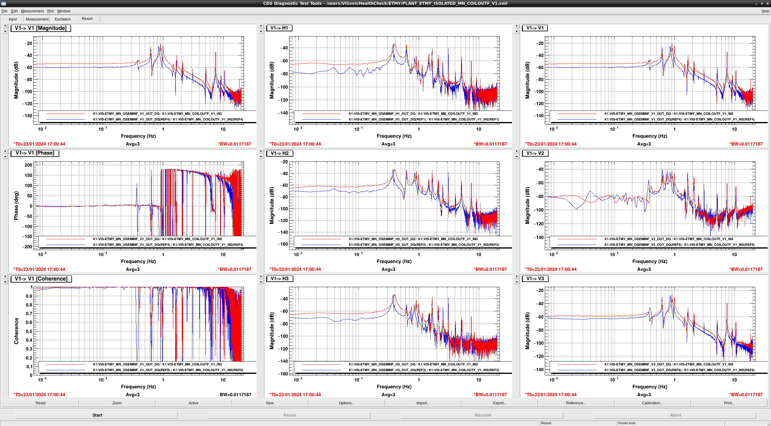
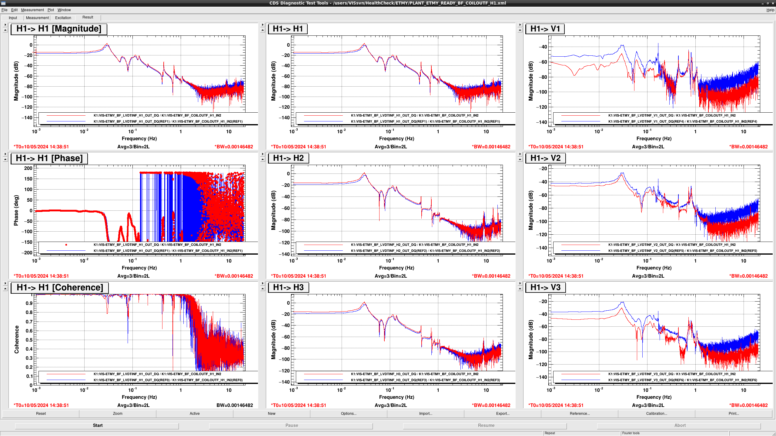
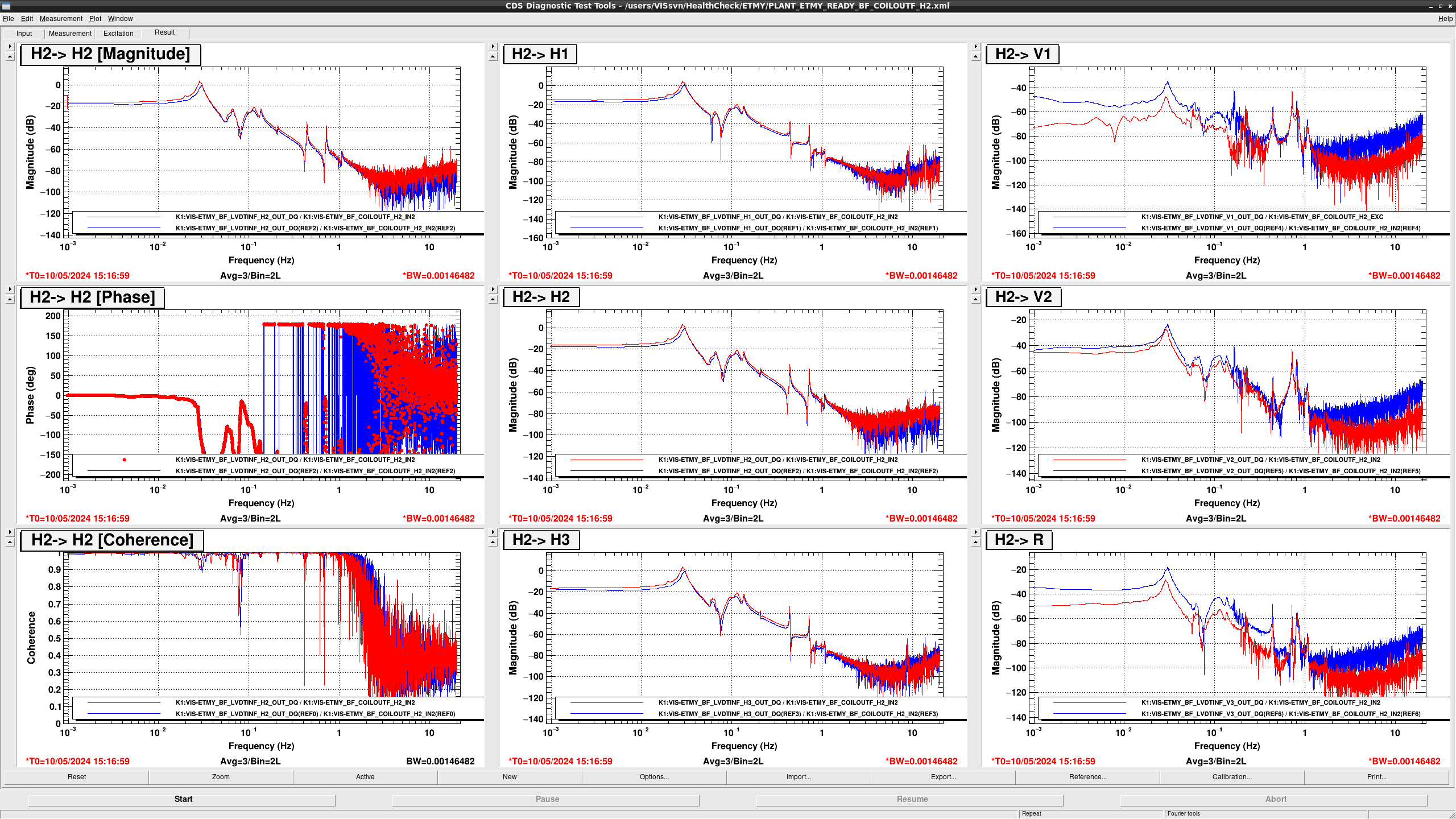
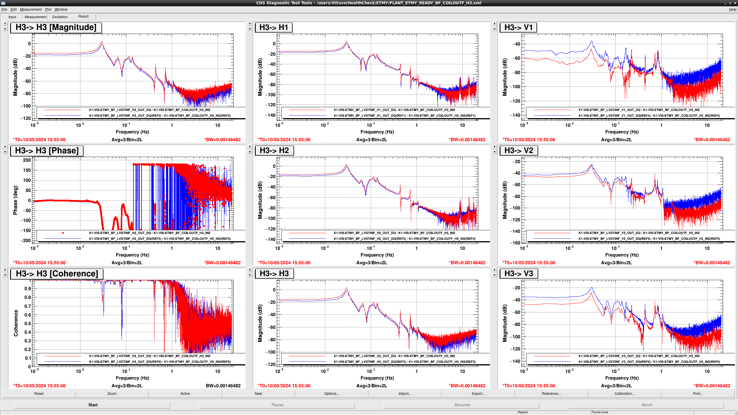
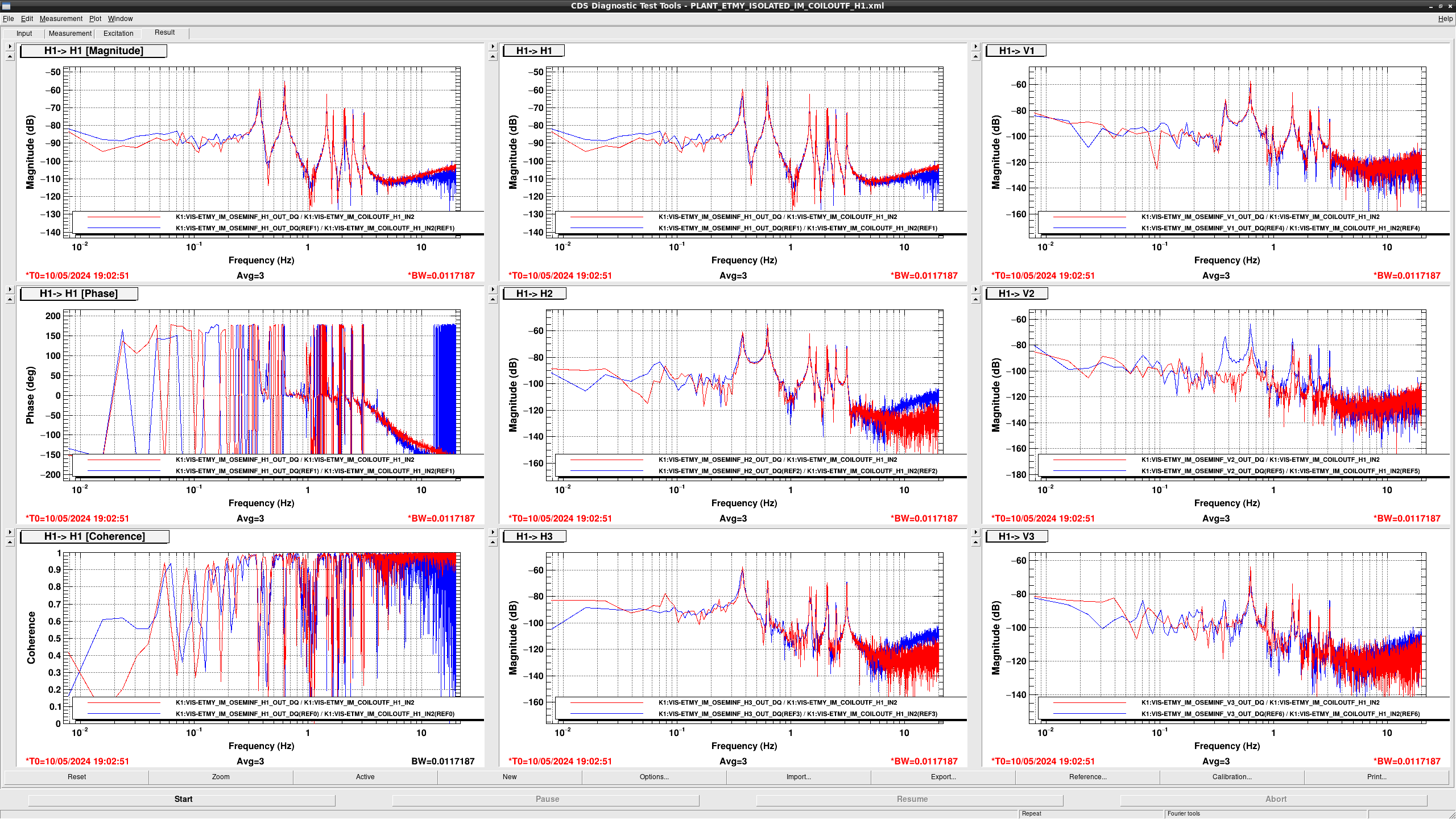
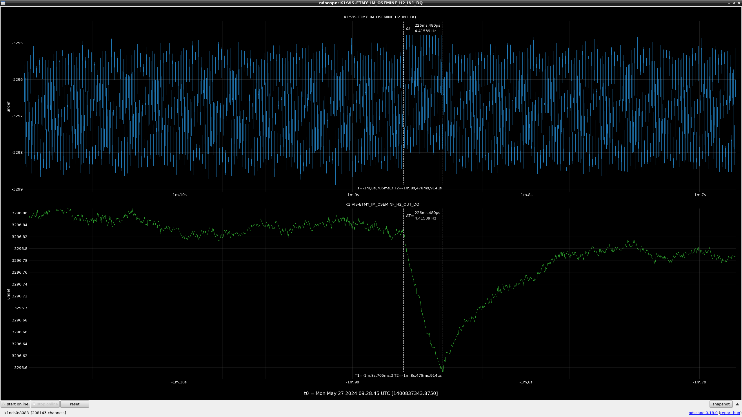
  • in COIL H1 > LVDT H3, the gain got smaller to -40dB, We found the H3 signal (K1:VIS-ETMY_BF_LVDTINF_H3_INMON) oscillated largly and then got smaller. Therefore, LVDT H3 seems to be dead.
  • in COIL {H1,H2,H3} > LVDT {V1,V2,V3}, from 0.2 Hz to 0.5 Hz, the gain became noisy. So BF may hit somewhere(?).
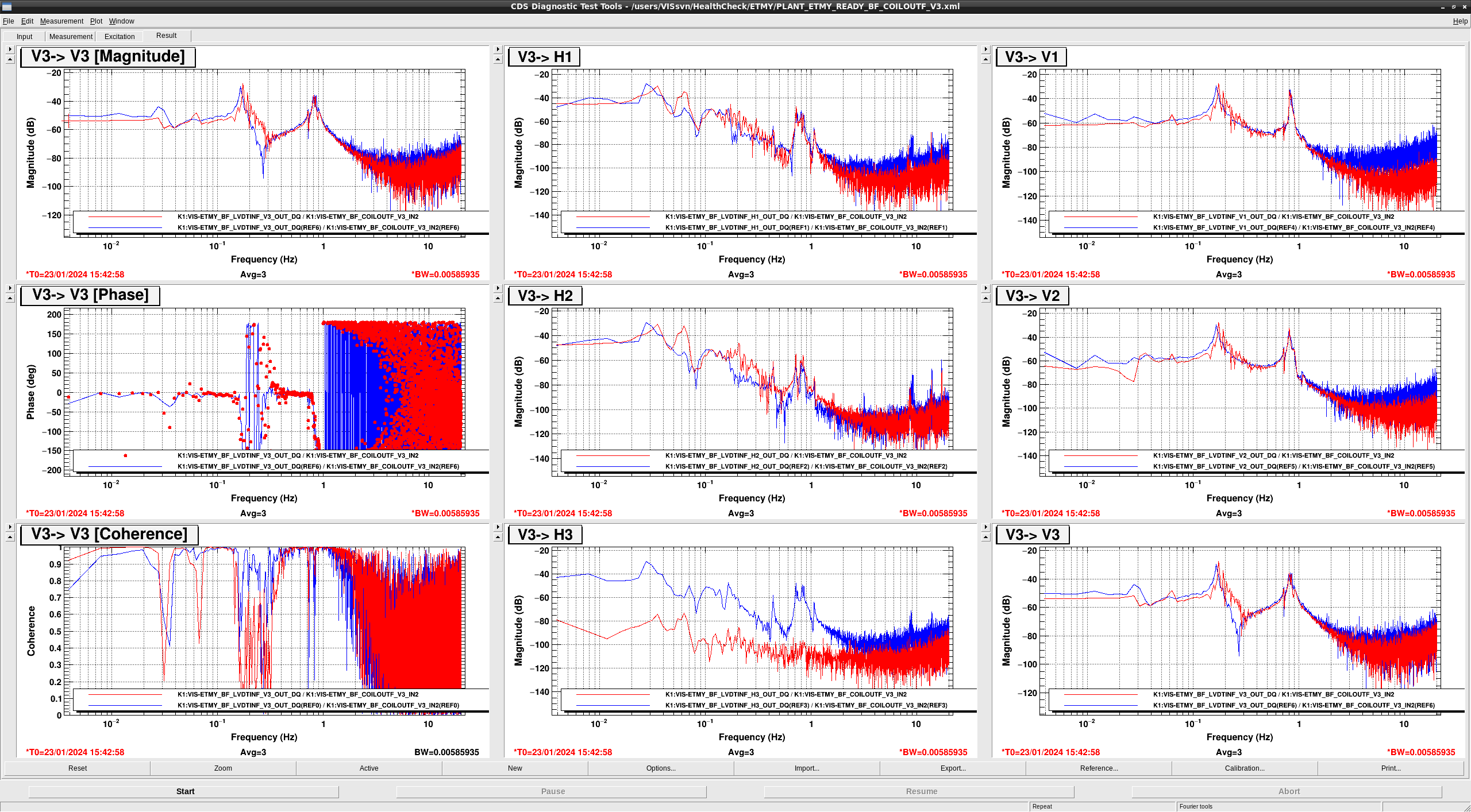
  • In COIL H3 > LVDT H3, the sign seems to be flipped...
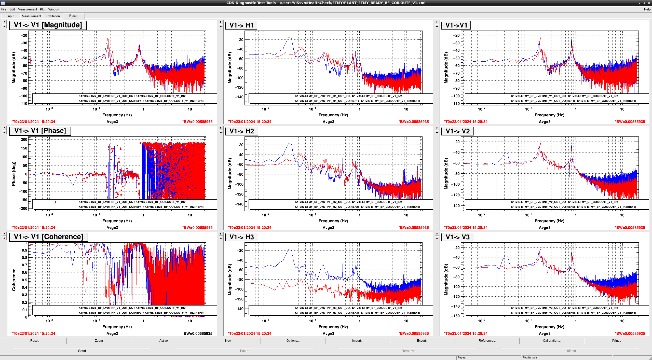
  • In COIL V1 > {V1,V2,V3} the resonance peak at 0.164 Hz  shifted to 0.175 Hz.
  • In Coil V1 > {H1,H2}, from 0.2 Hz to 0.5 Hz, the gain became noisy.
  • In COIL V1 > {H1,H2,V1,V2,V3}, the 0.3 Hz peak disappeared maybe because the damping process was added between each measurement in this time so the resonances of other DoFs were damped.
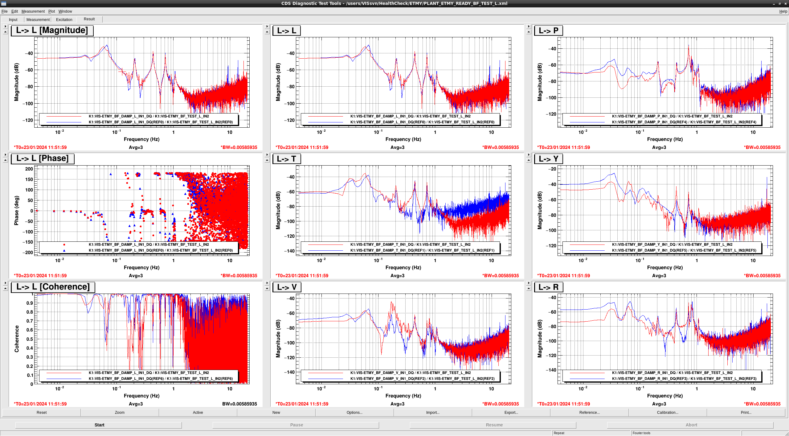
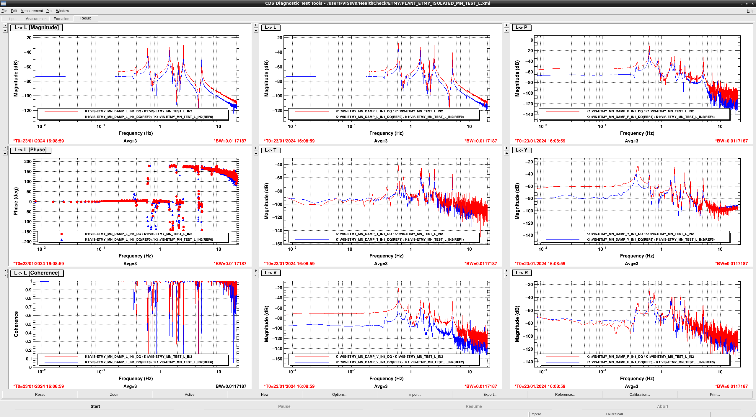
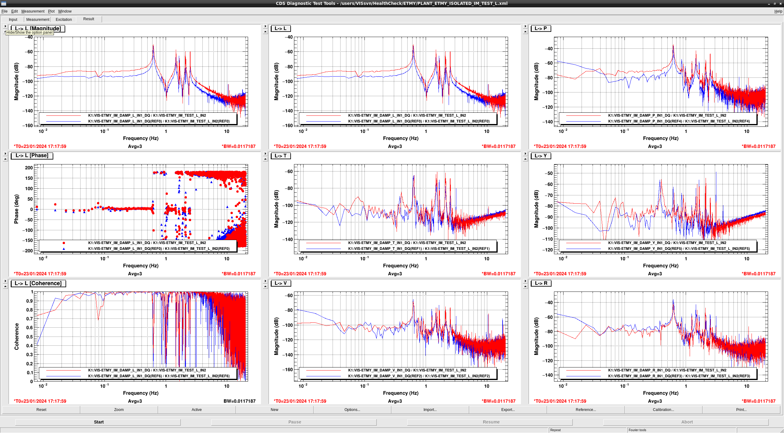
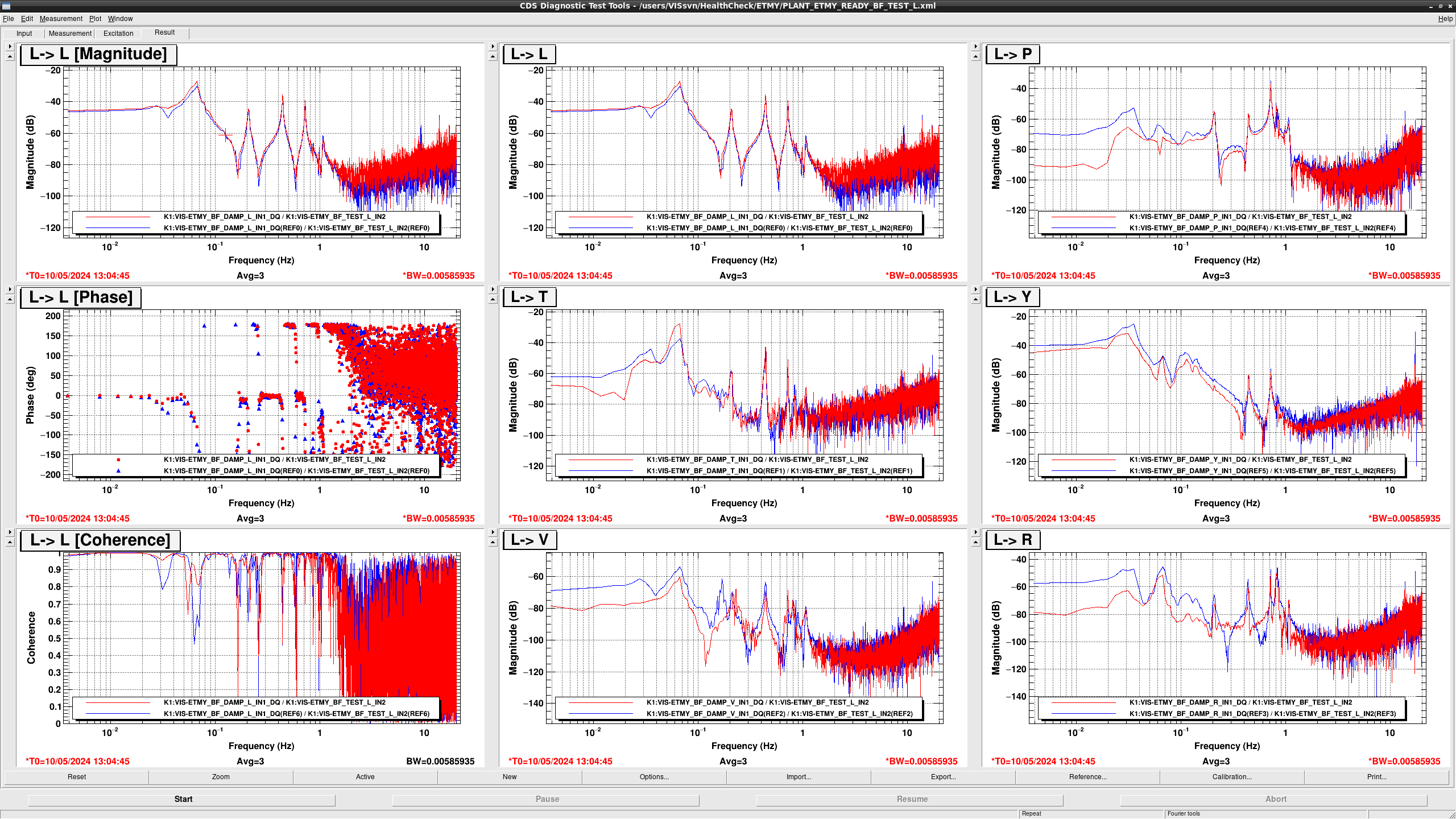
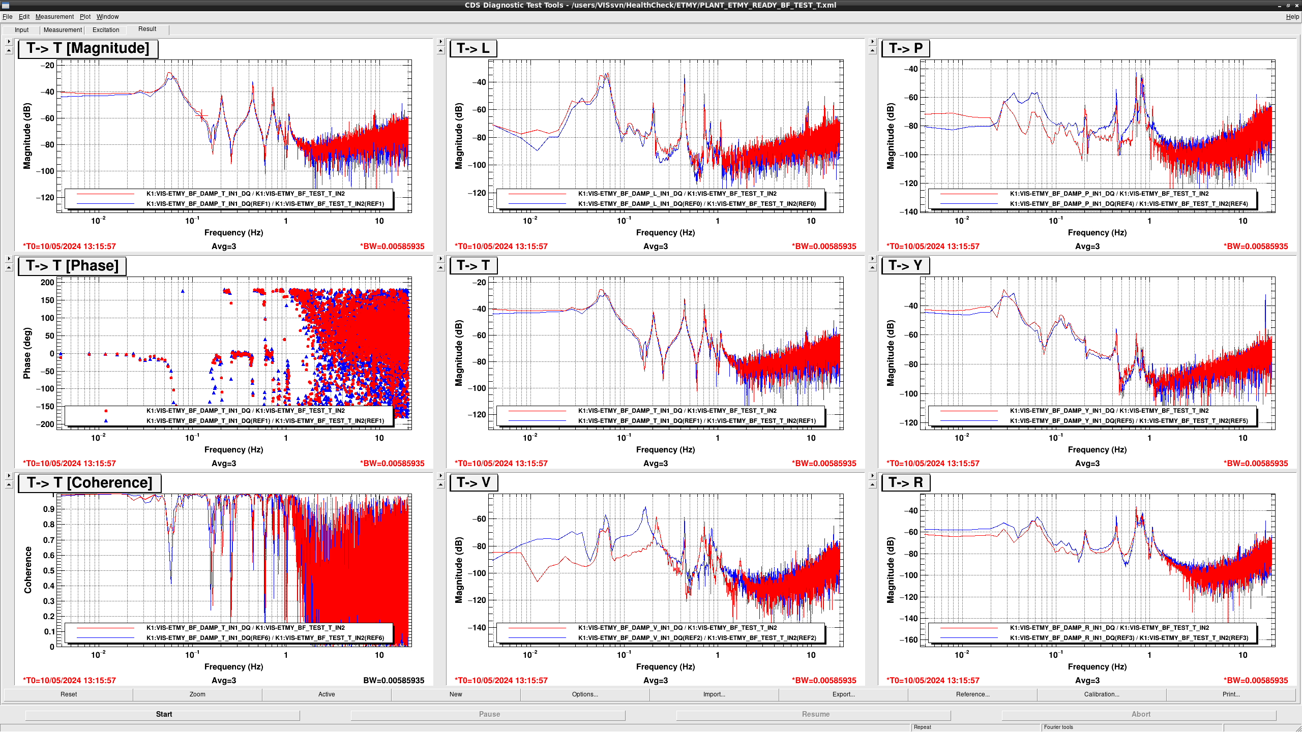
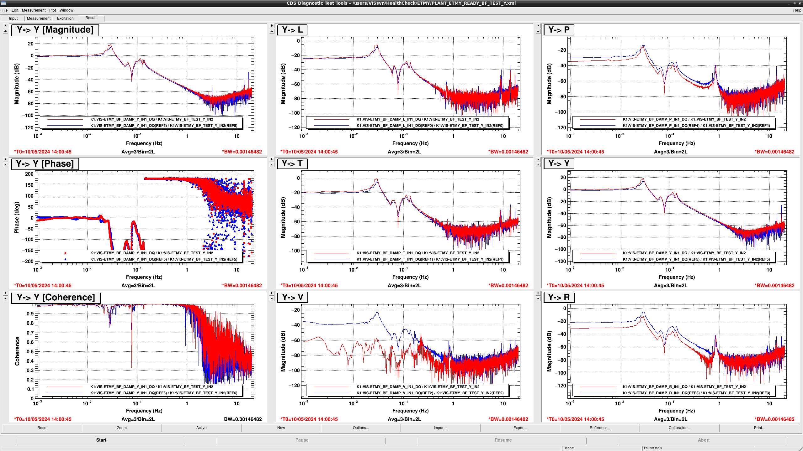
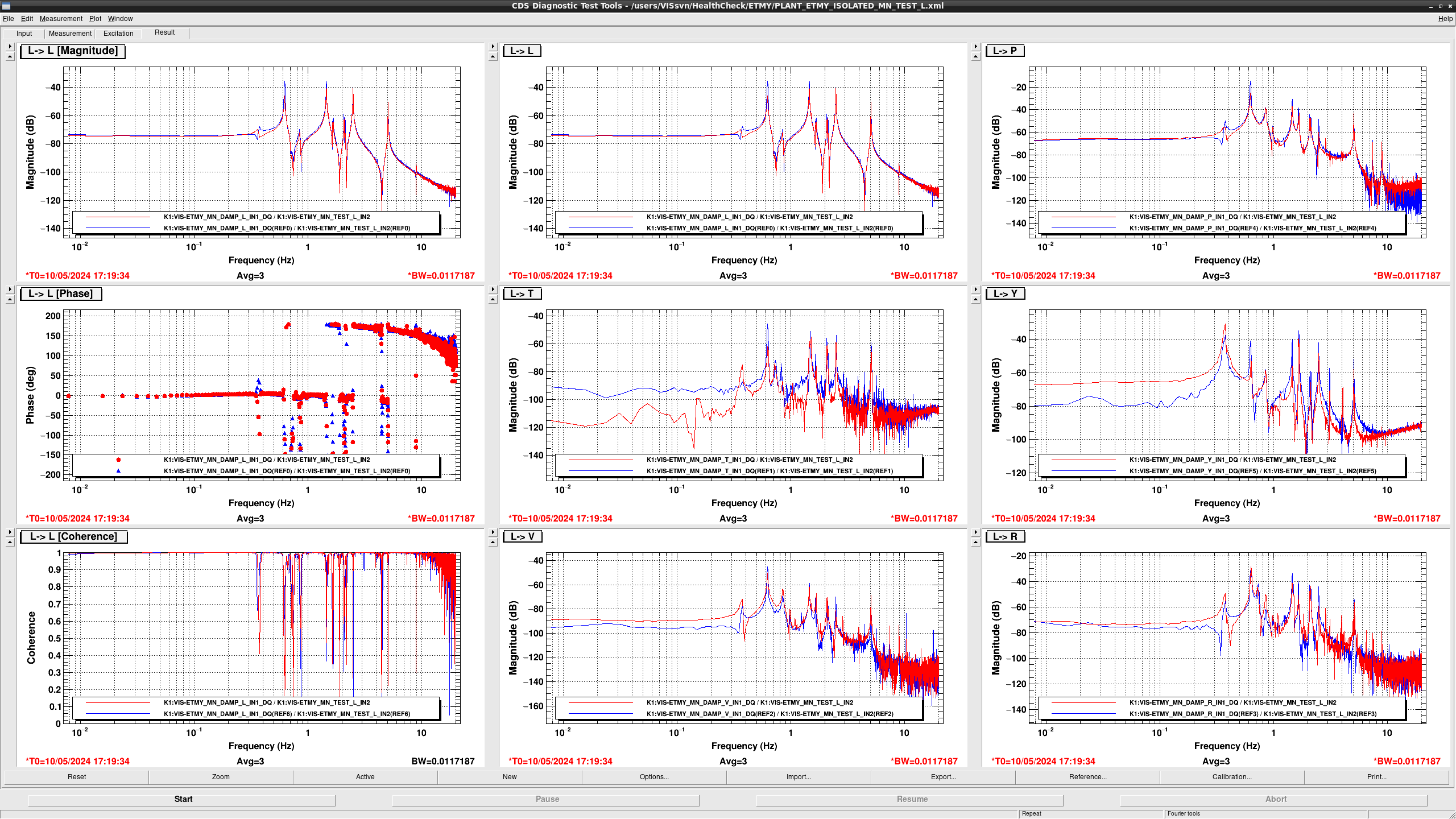
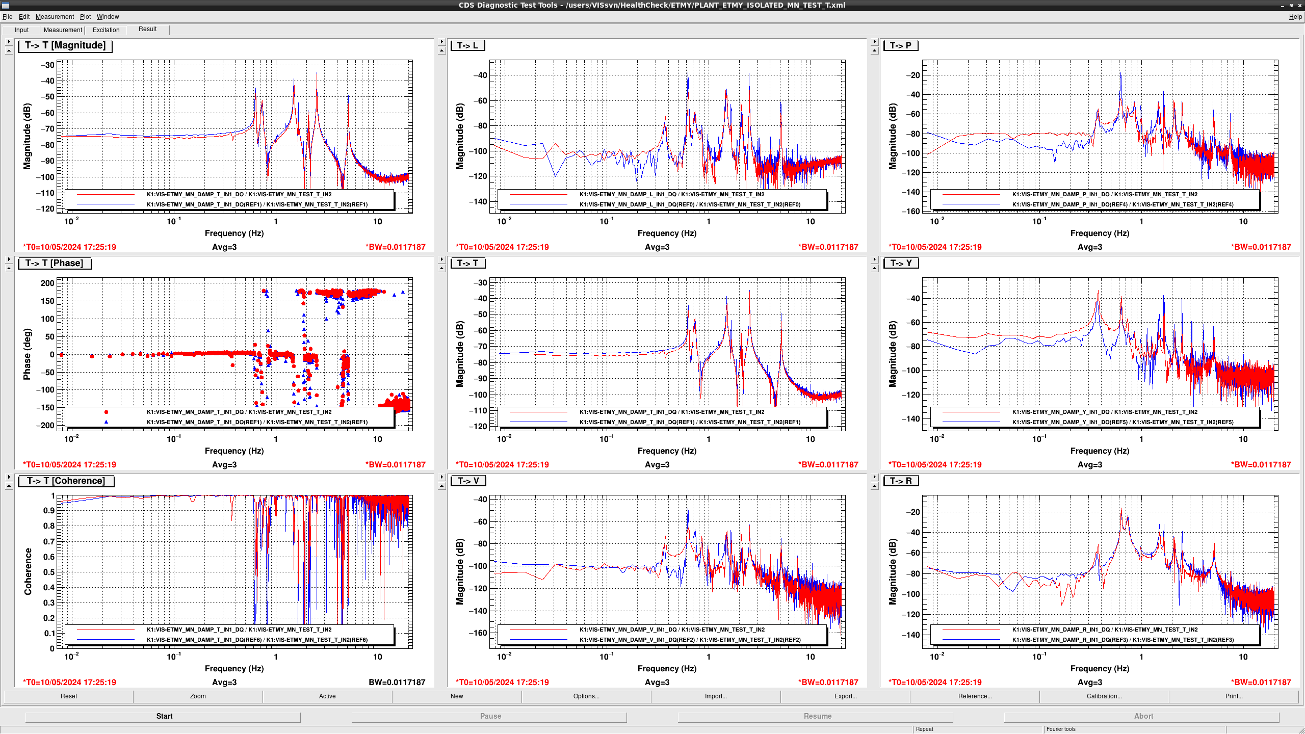
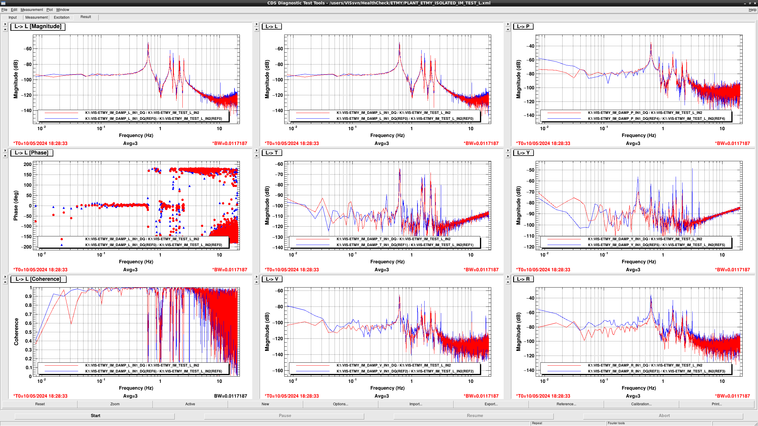
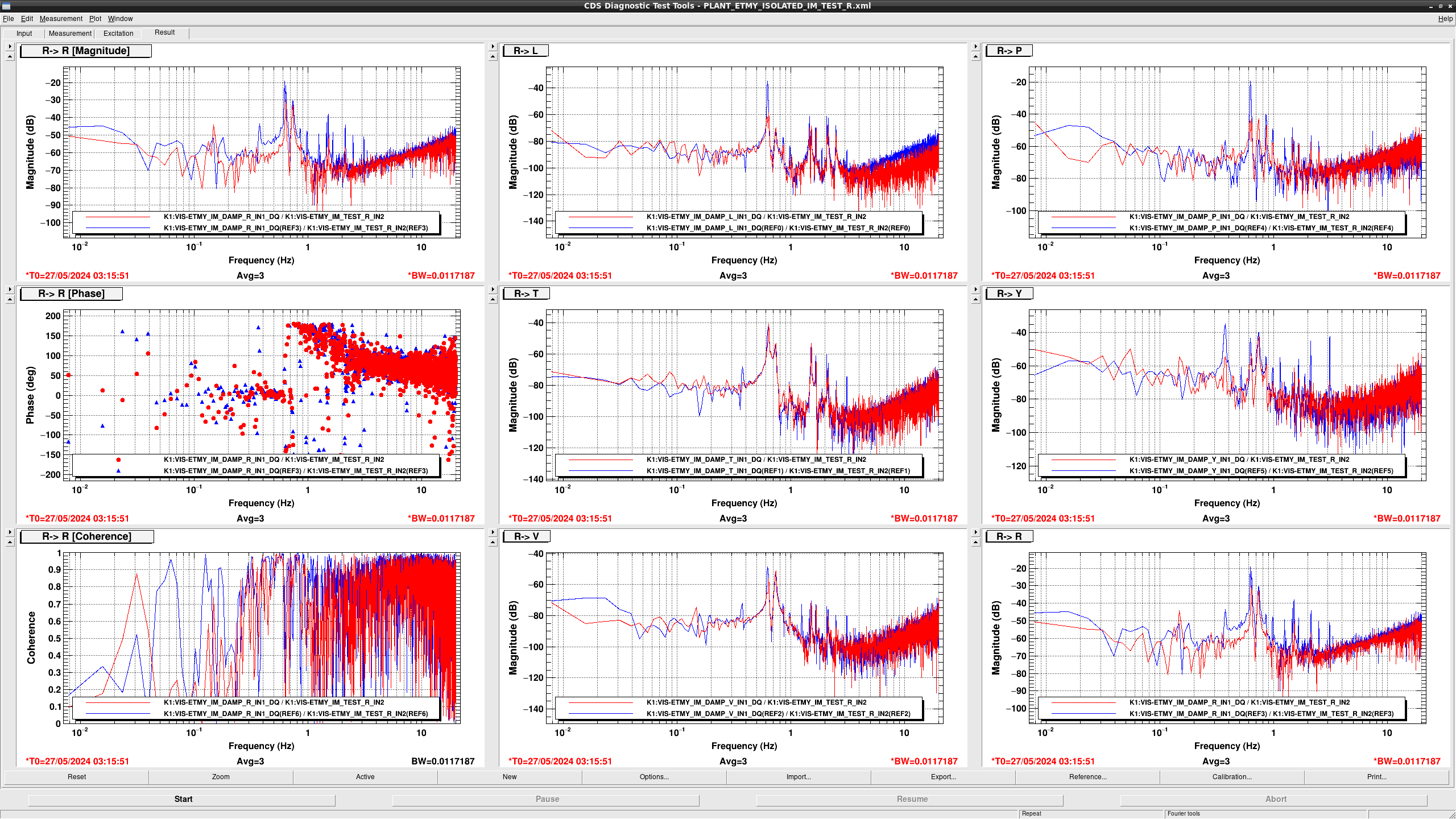
  • In TEST L > T and Y, the 0.438 Hz and 0.718 Hz resonance in L direction appear more clearly maybe because LVDT H3 is not working.
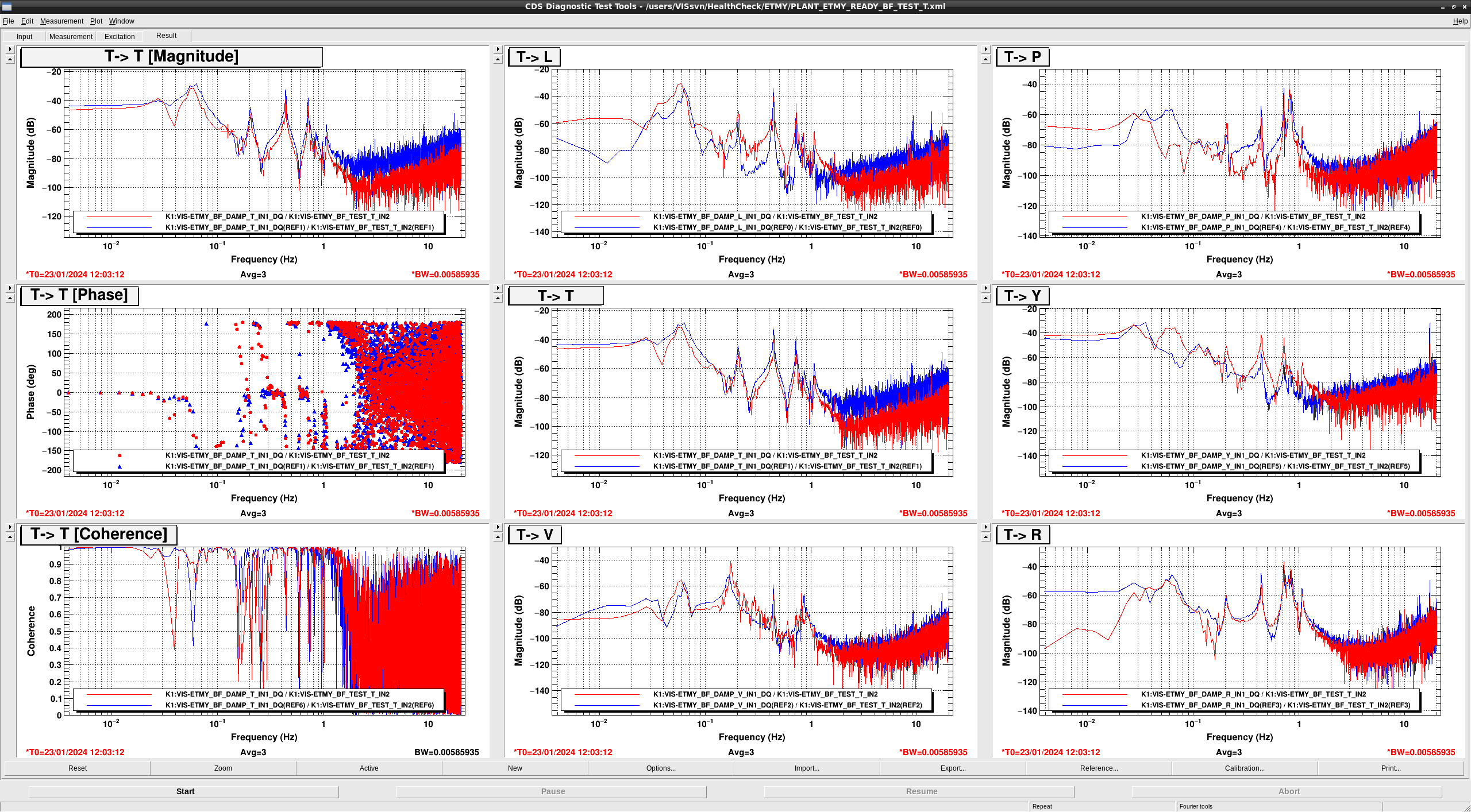
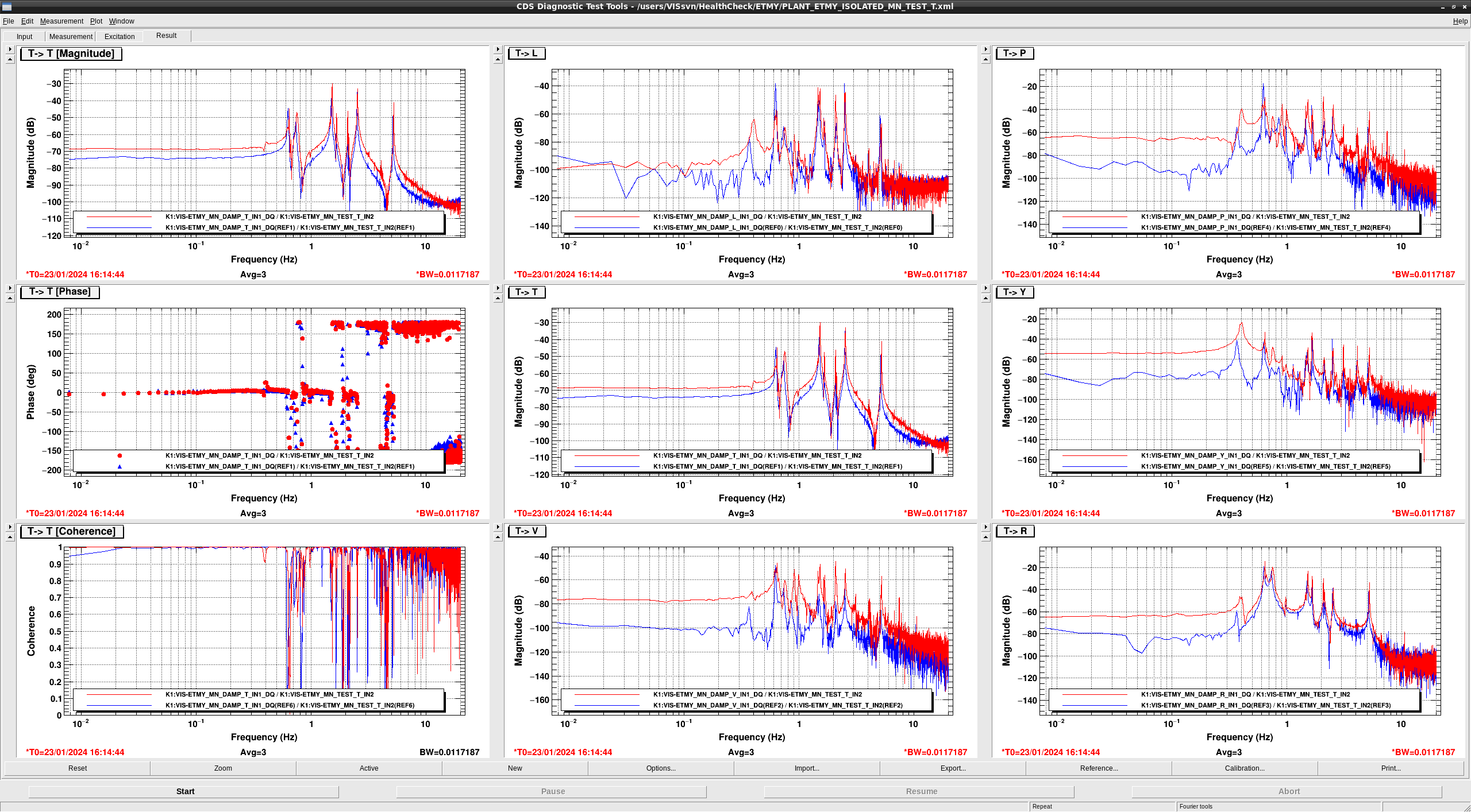
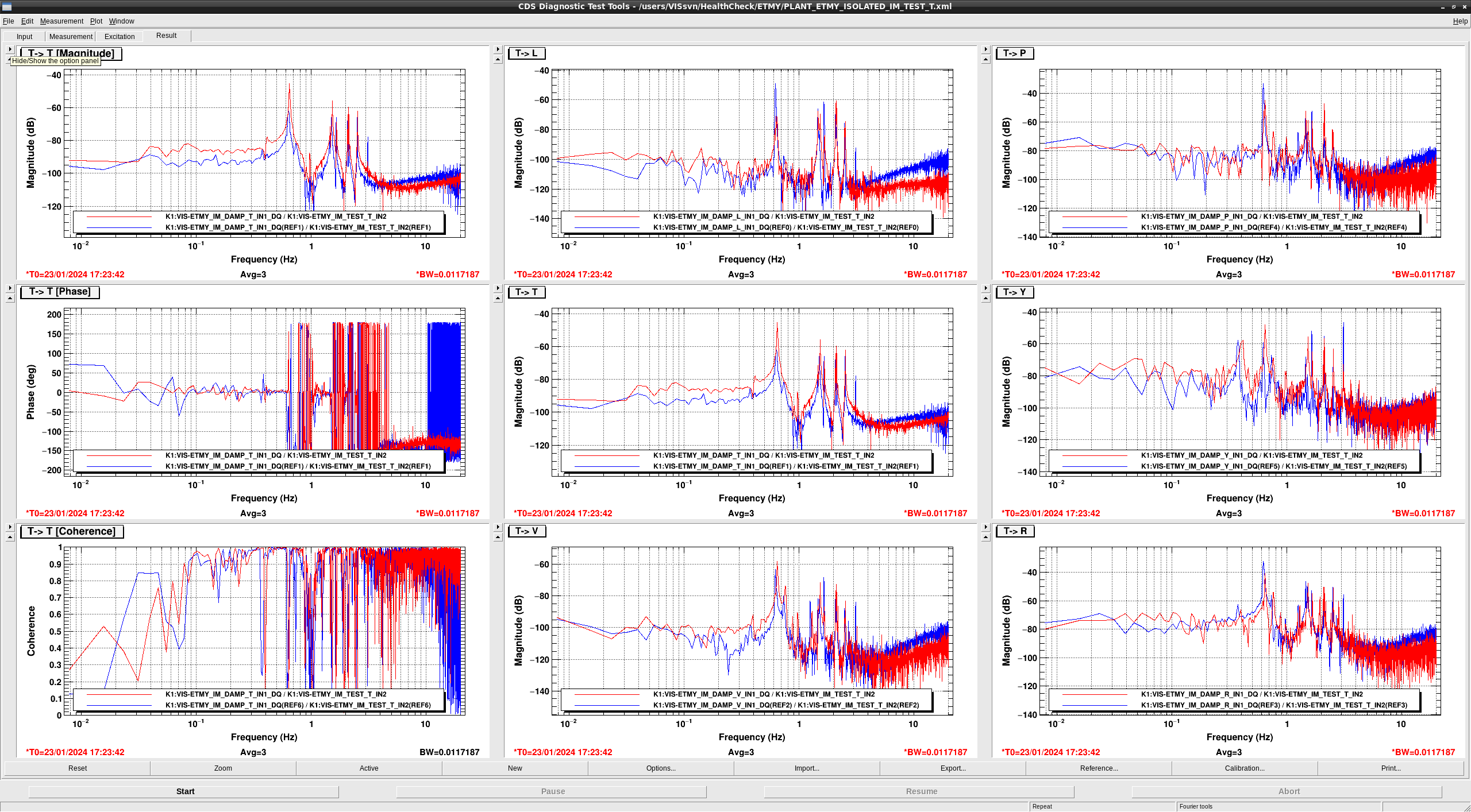
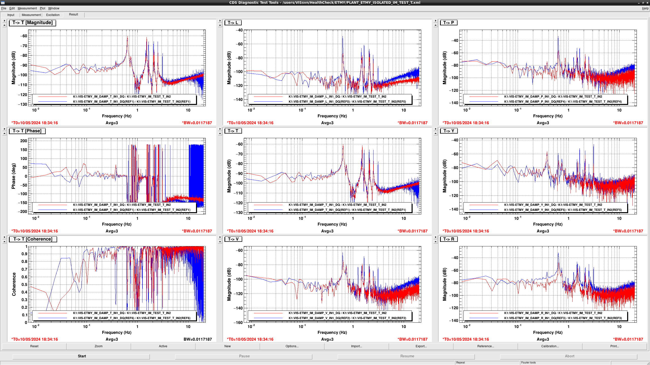
  • in TEST T > T and P, the overall gains got smaller. In TEST T > Y the 0.438 Hz and 0.718 Hz resonance in L direction appear more clearly maybe because LVDT H3 is not working.
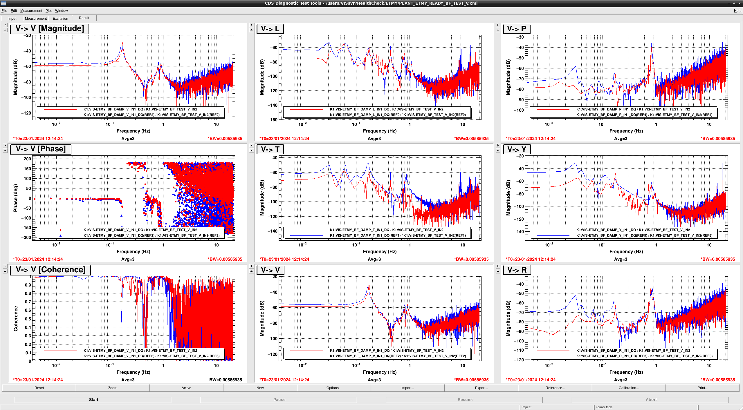
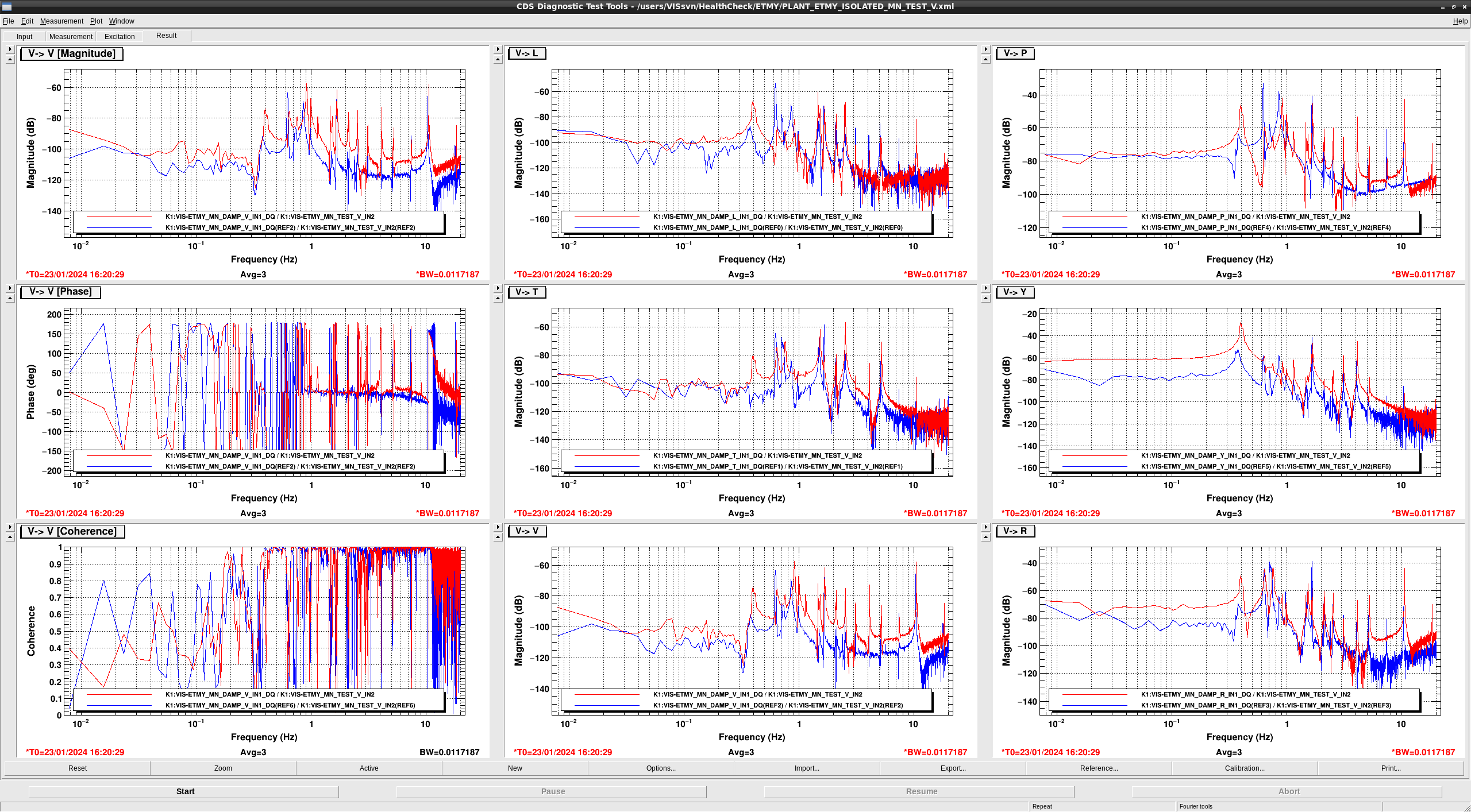
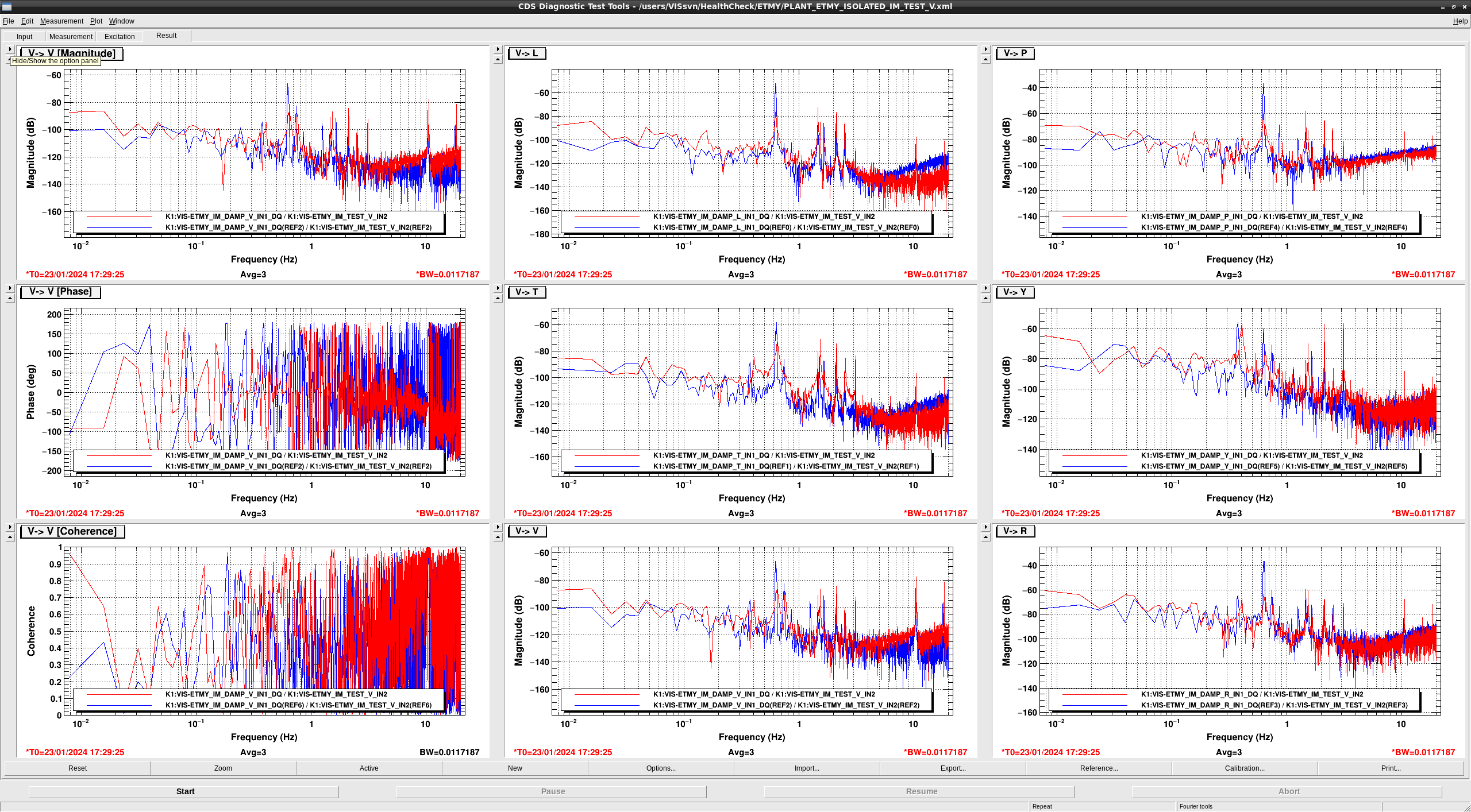
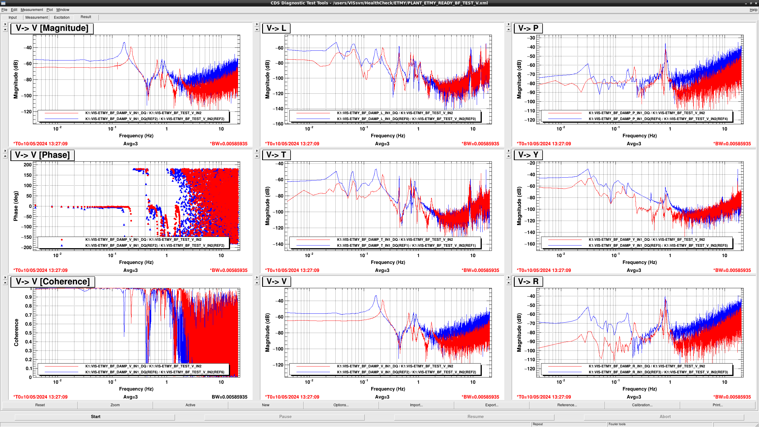
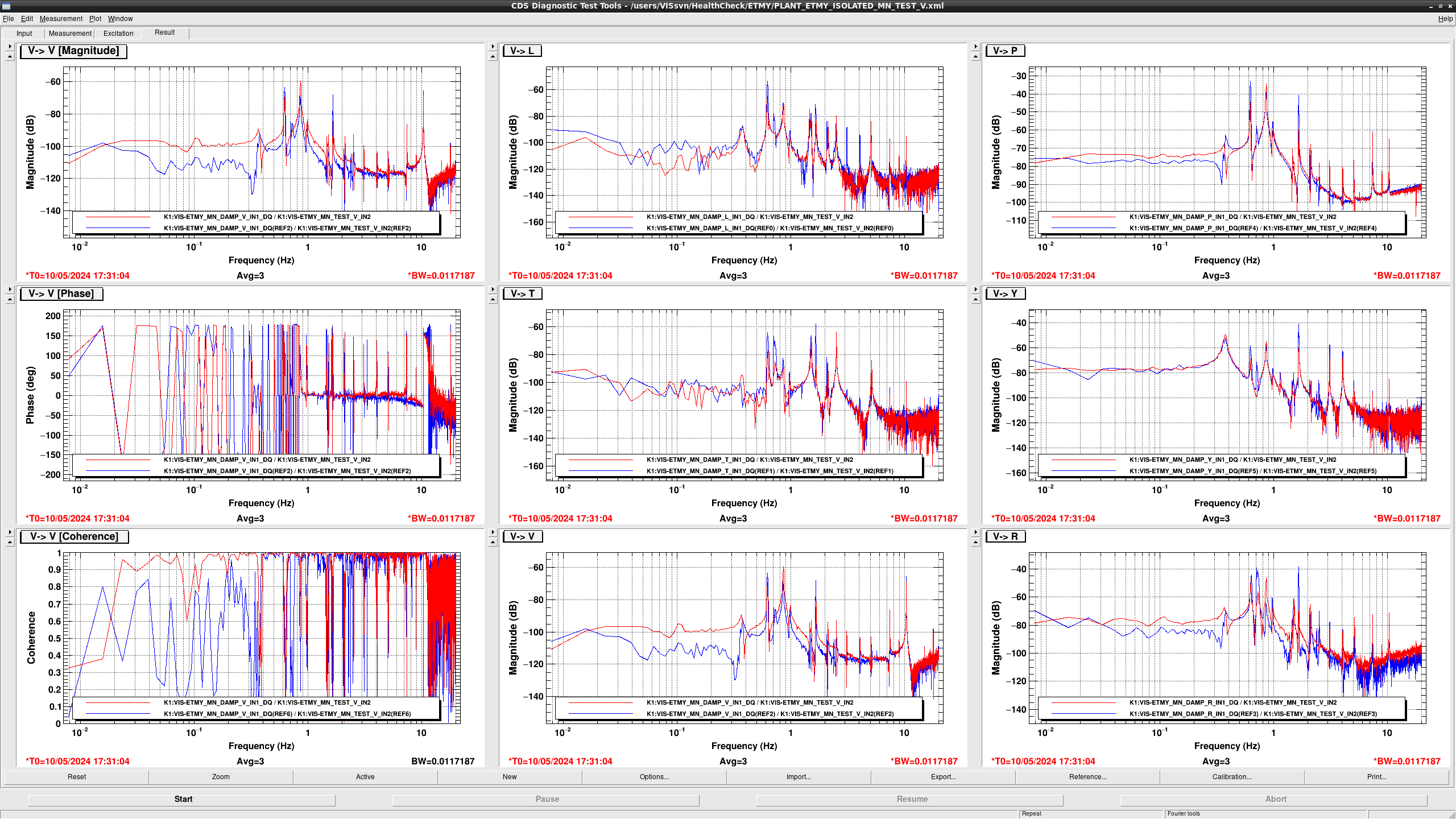
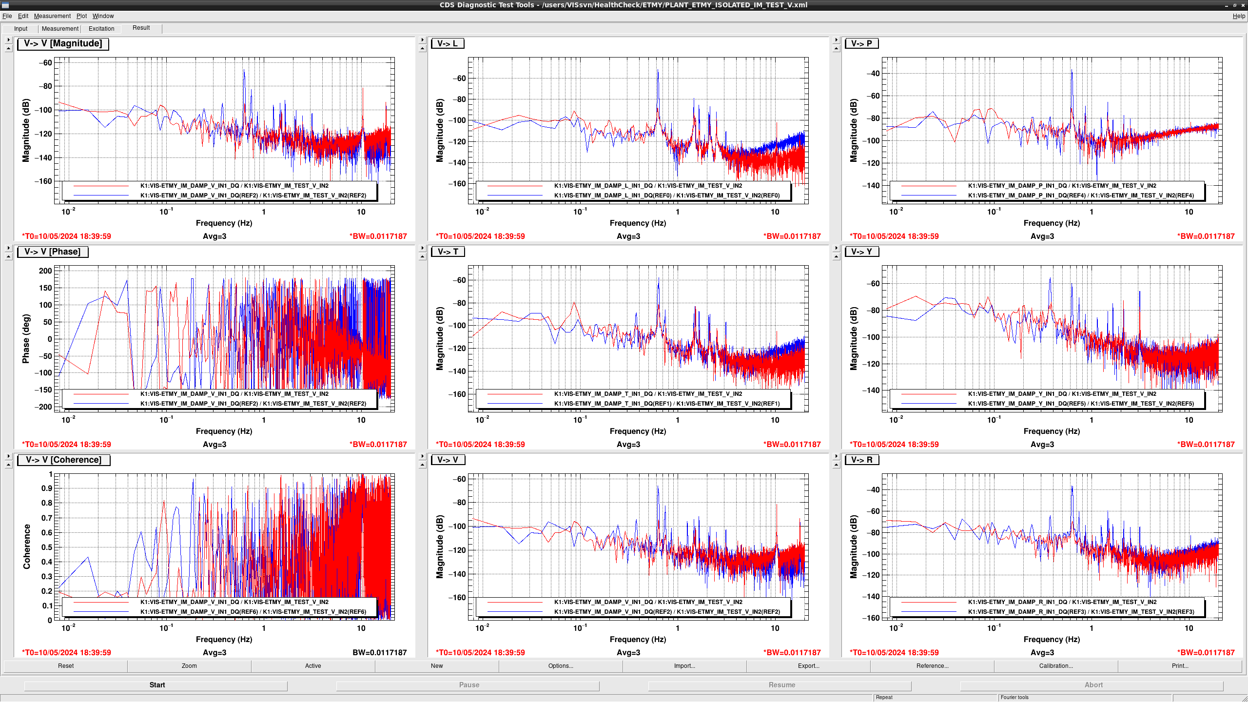
  • In TEST V > V, DC gain got smaller to -5dB.
  • In TEST V > T and Y, Their shapes seems to be changed. 
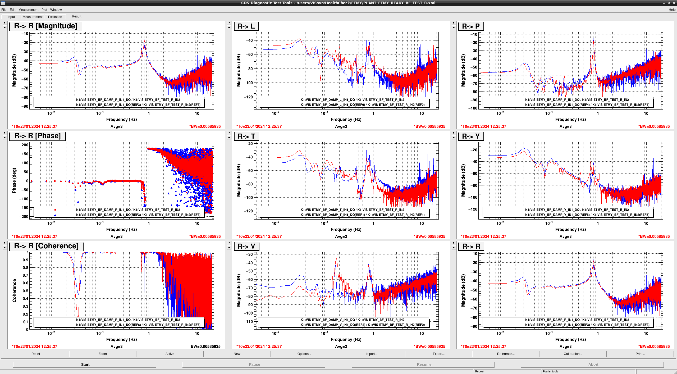
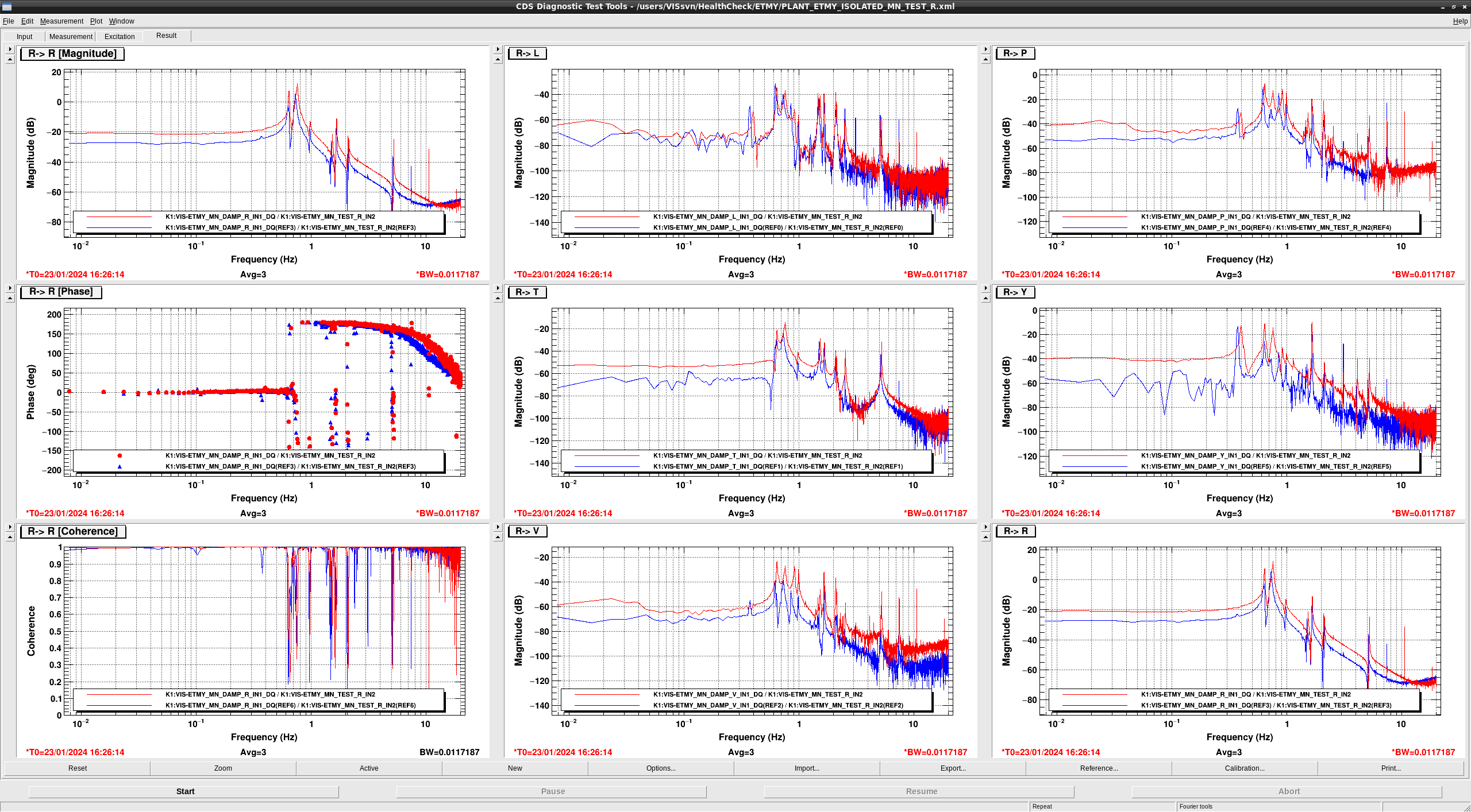
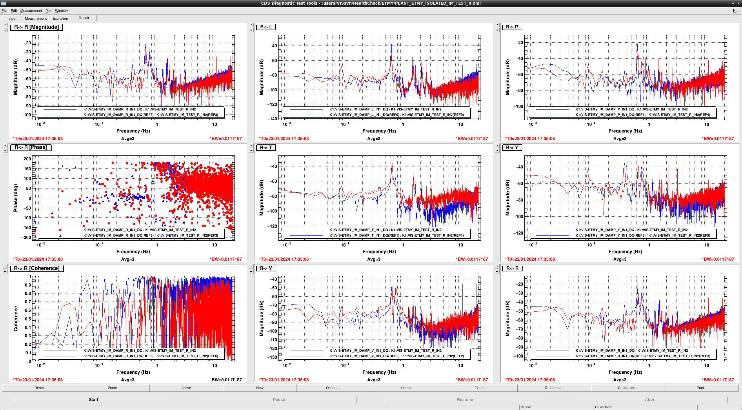
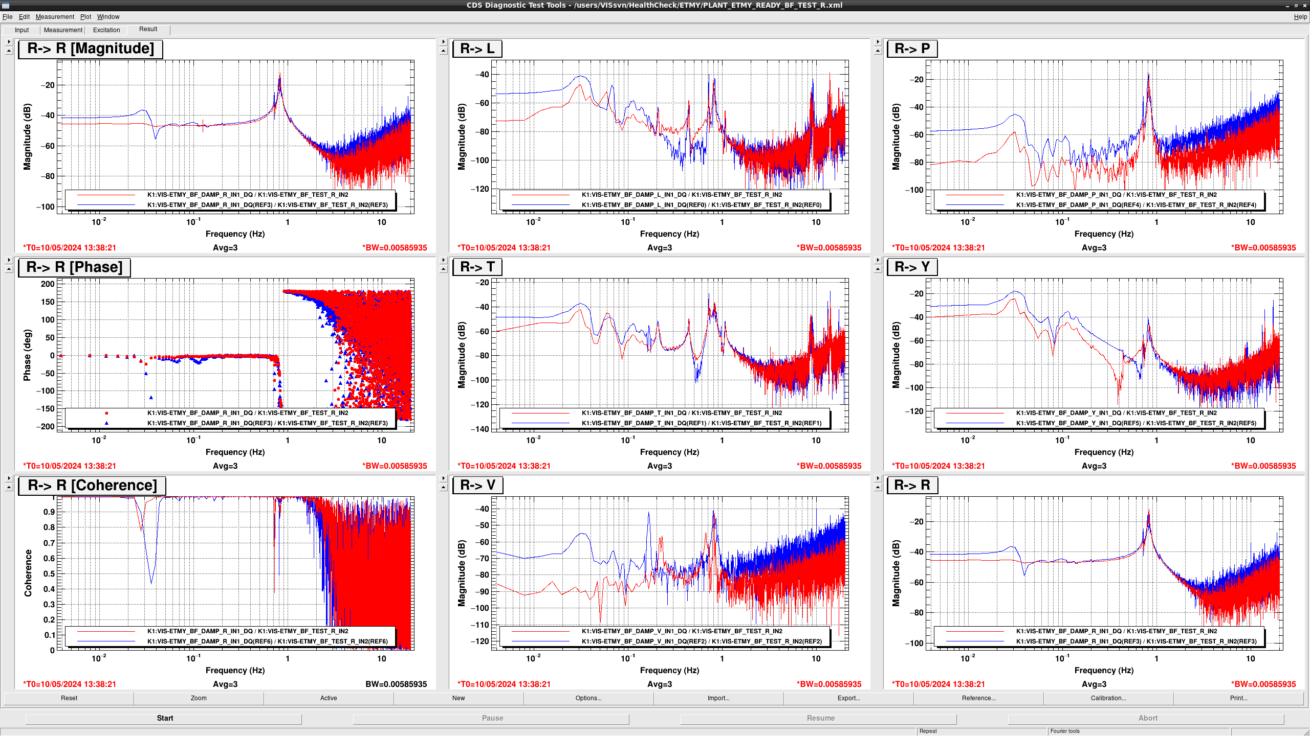
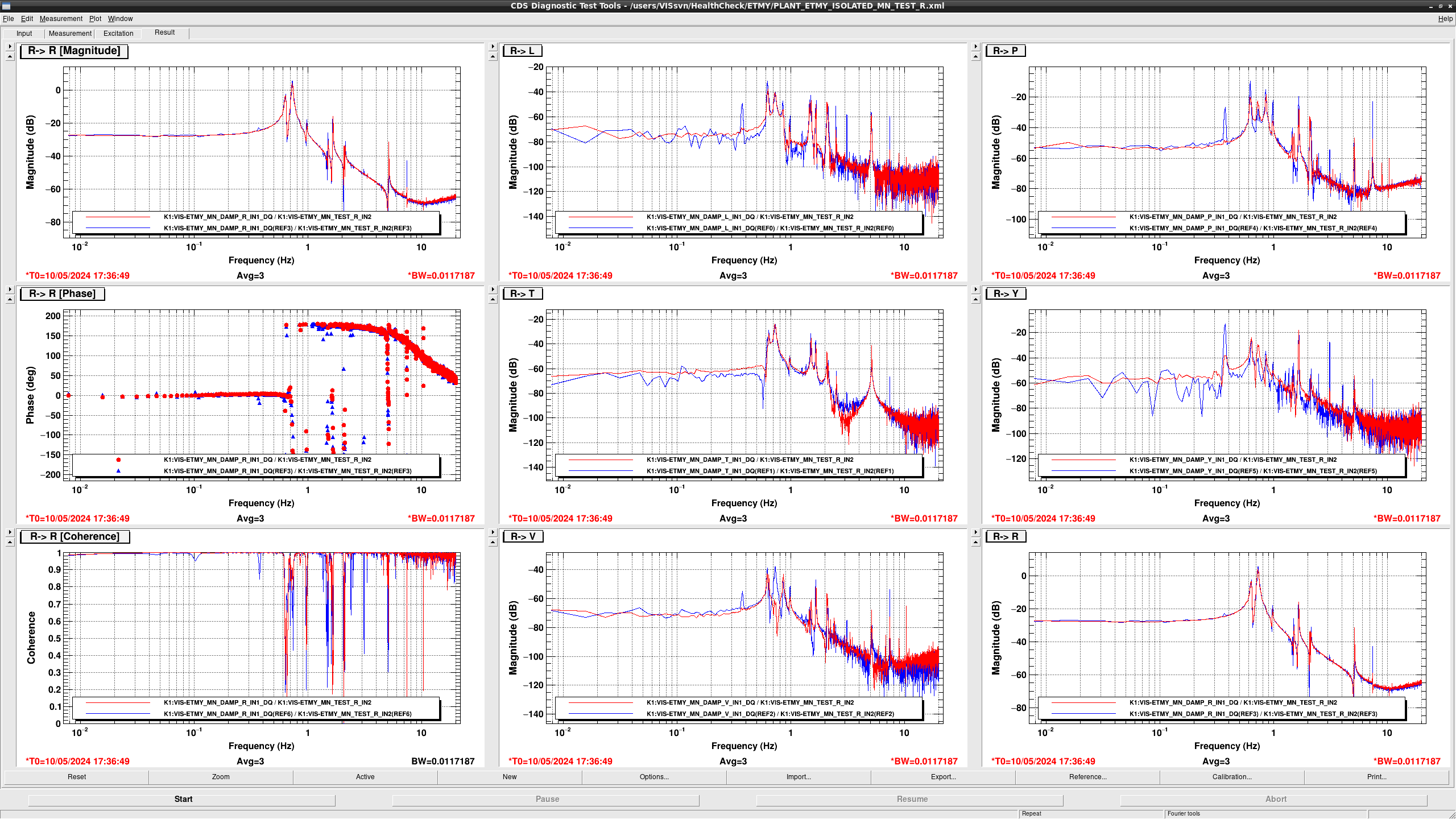
  • In TEST R > R, the DC gain got smaller -5dB
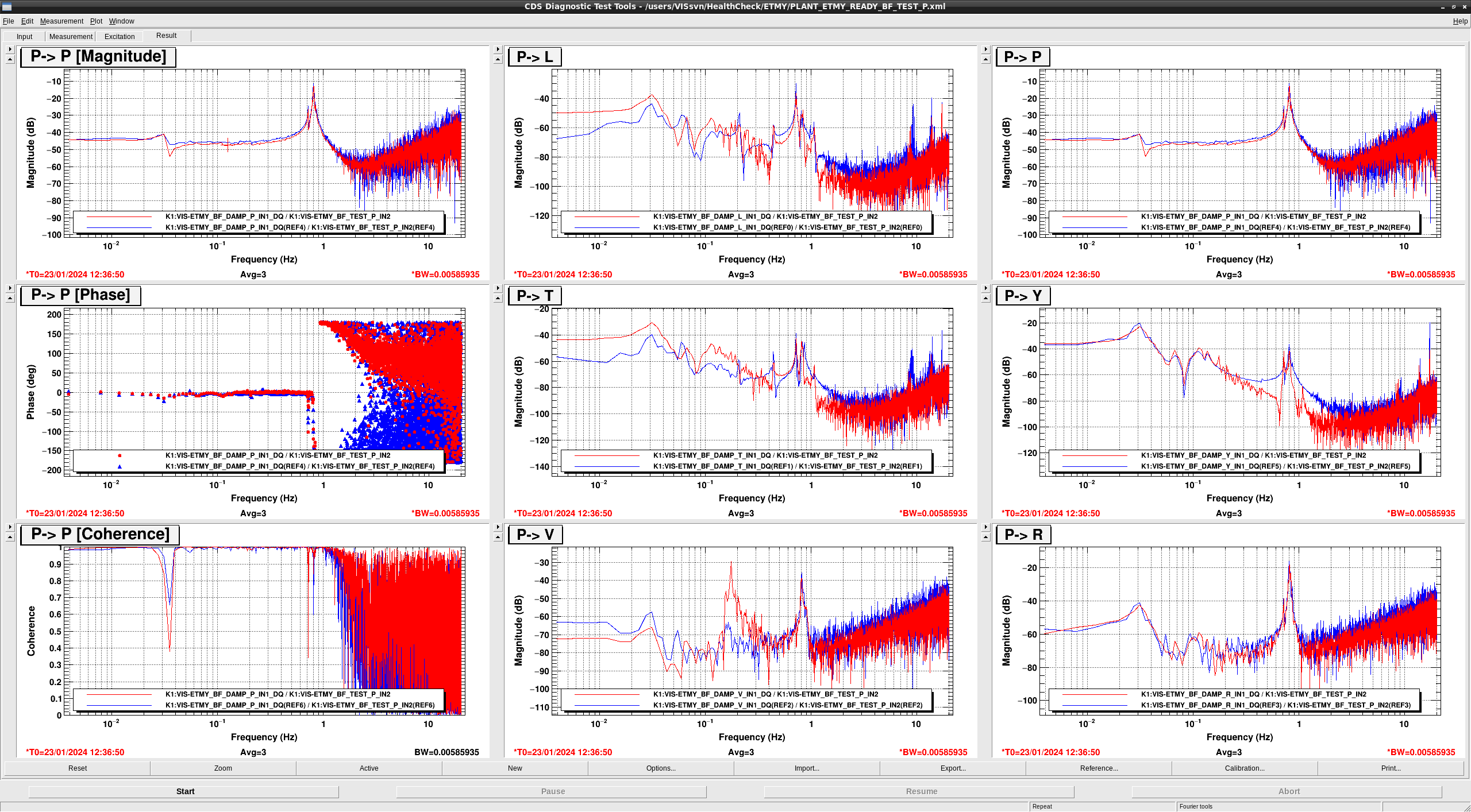
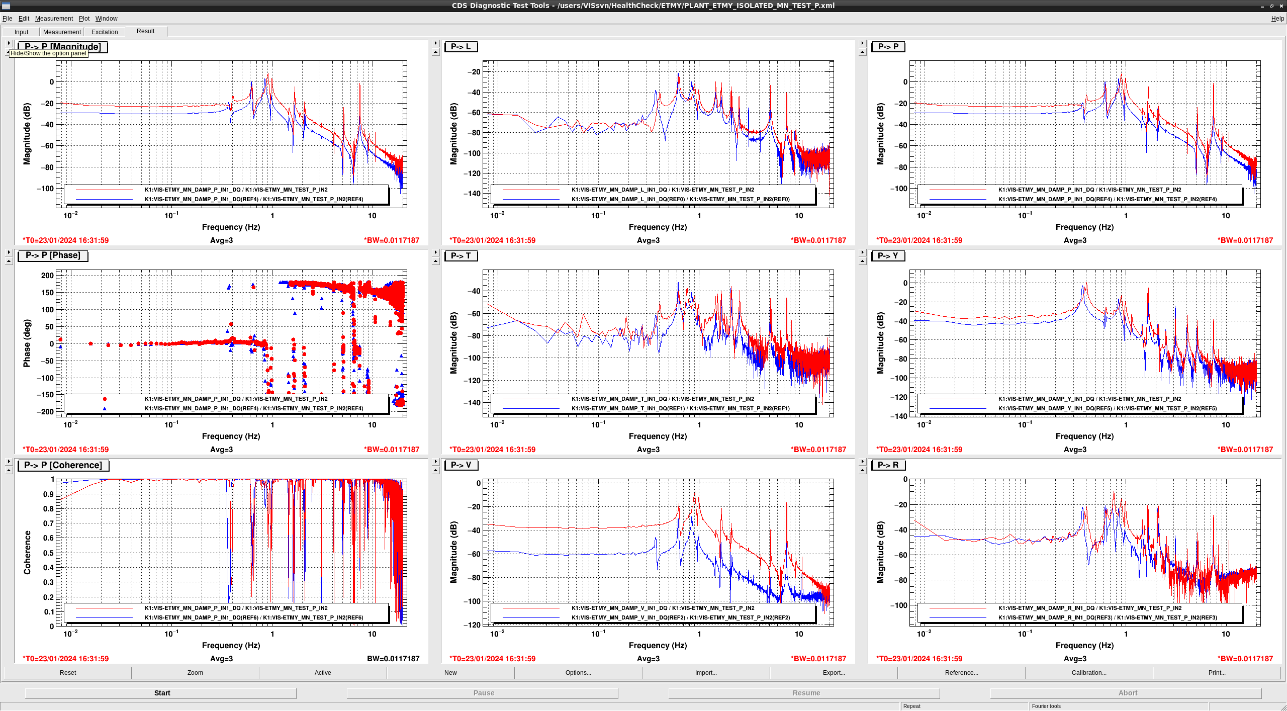
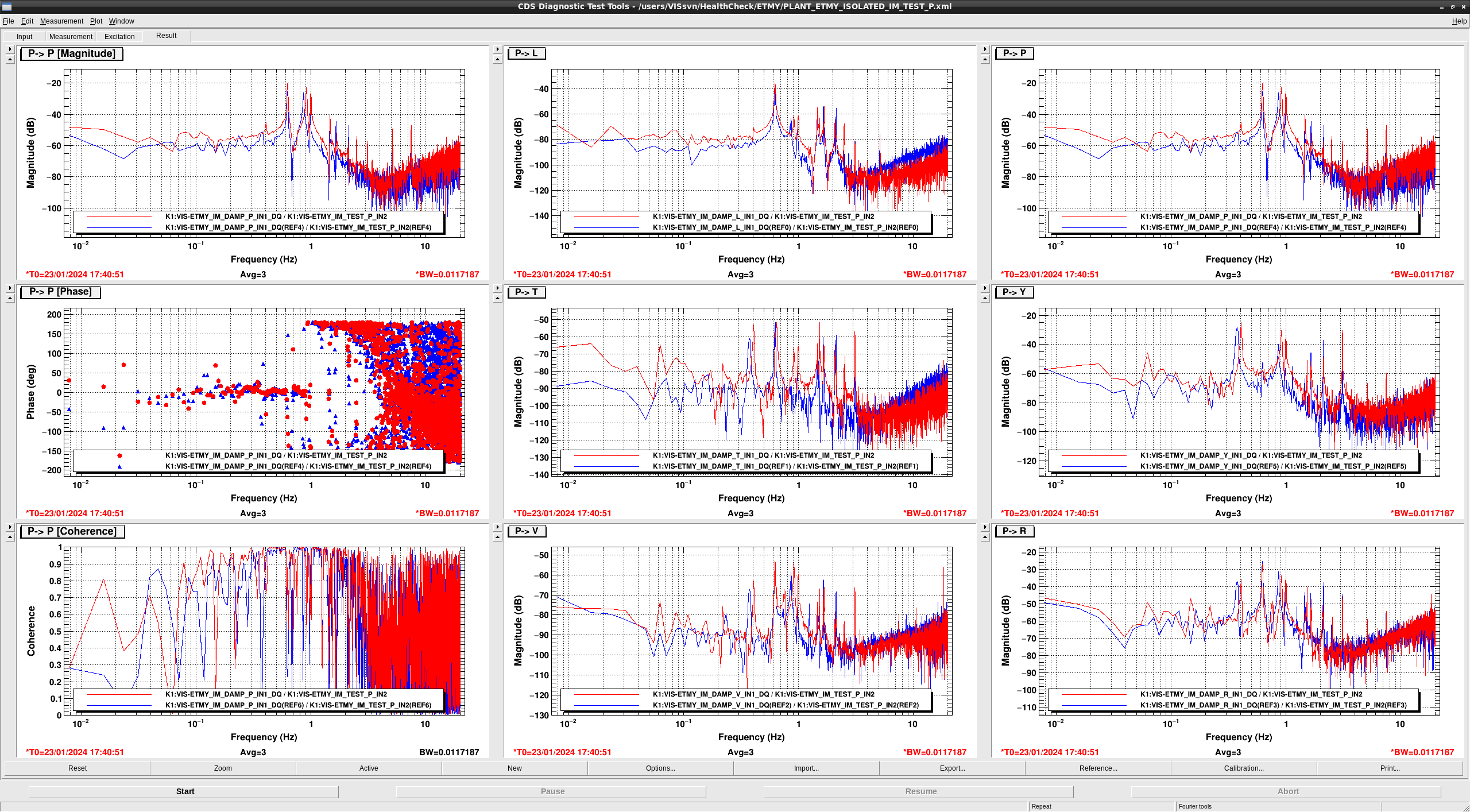
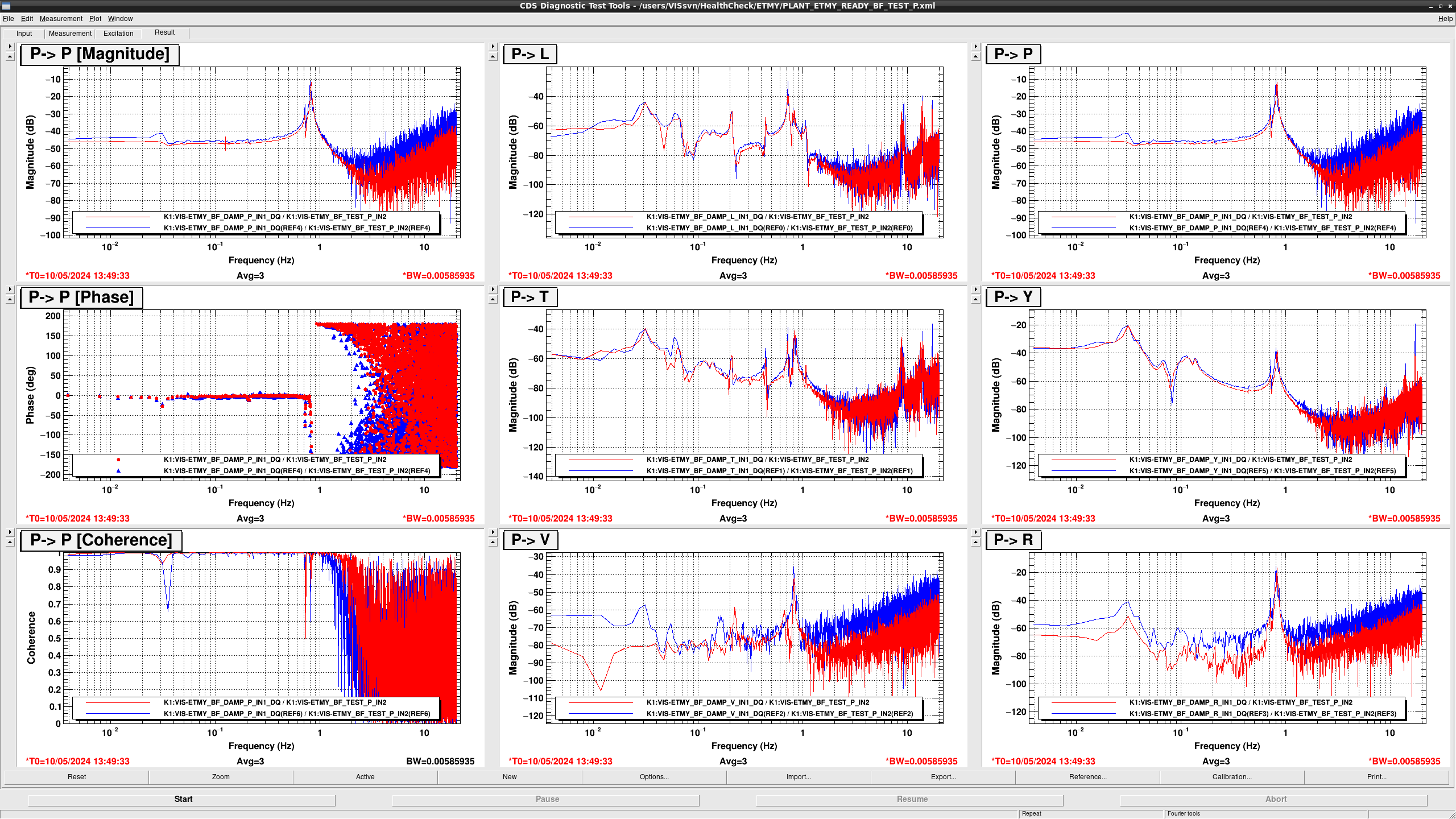
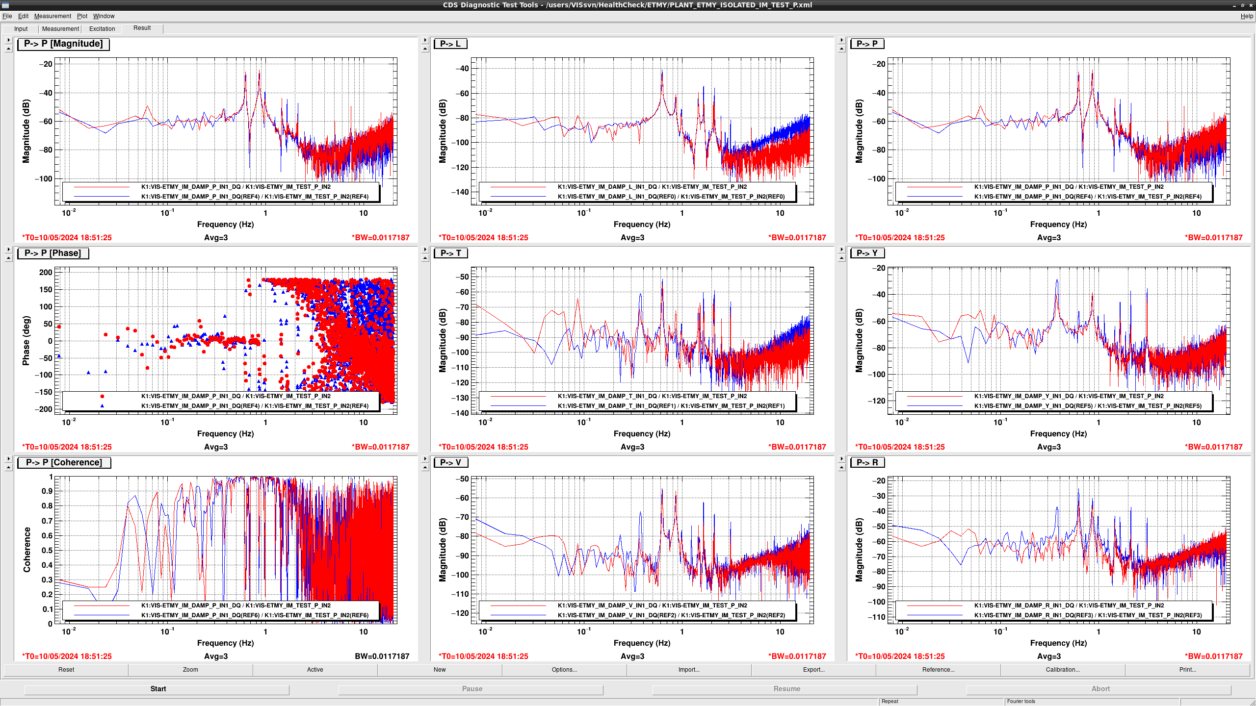
  • In TeST P > P, the DC gain got smaller slightly.
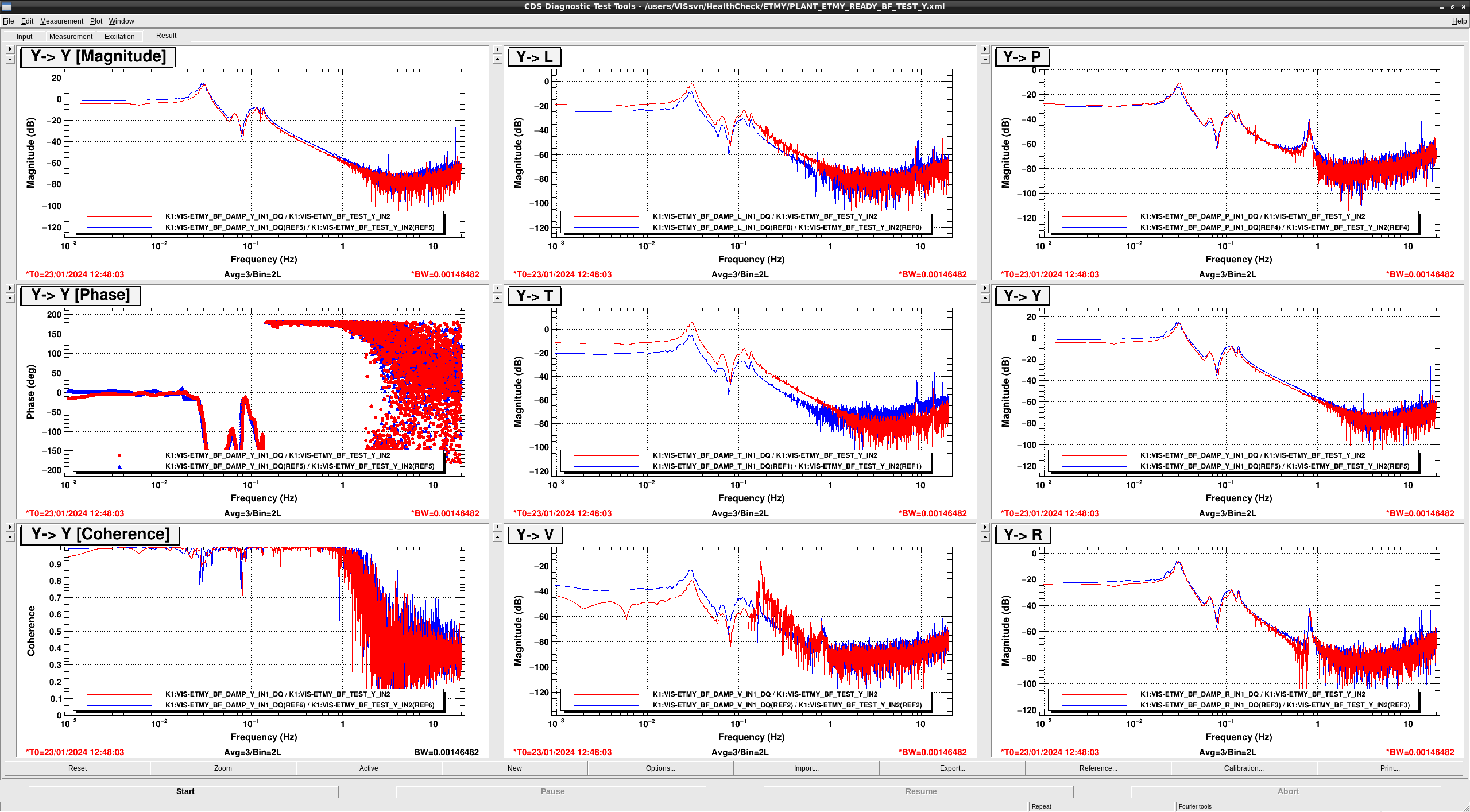
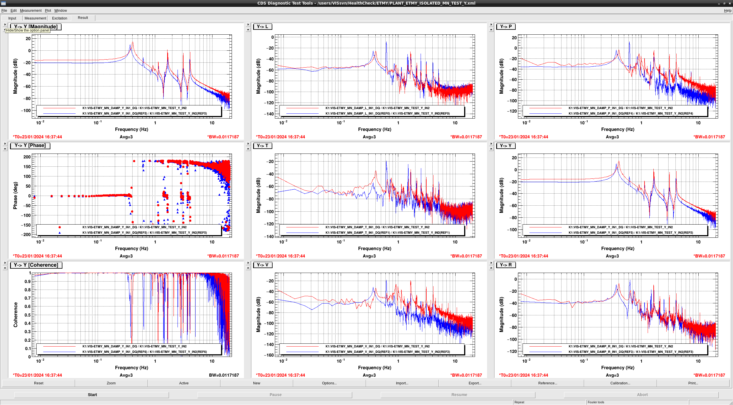
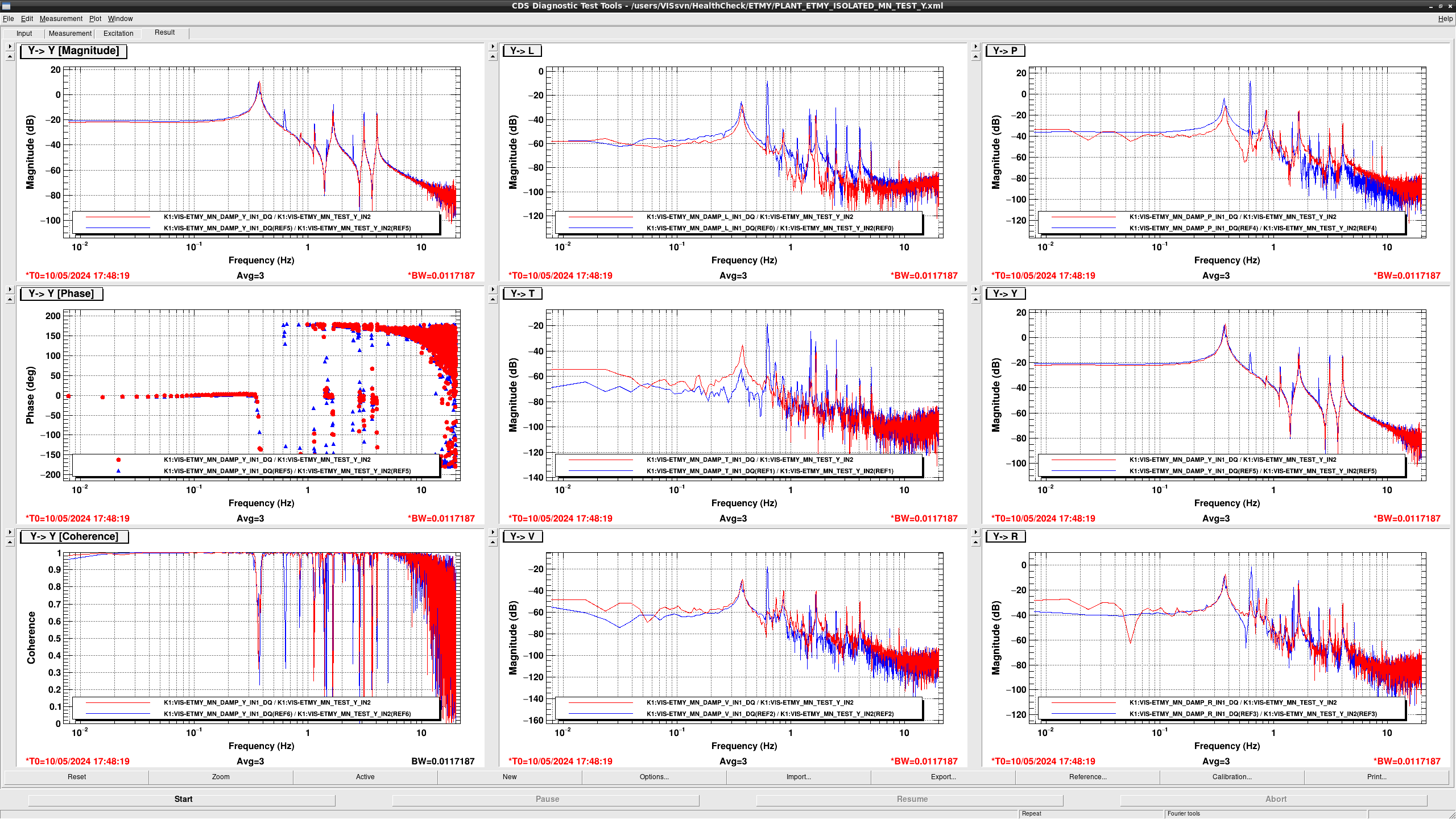
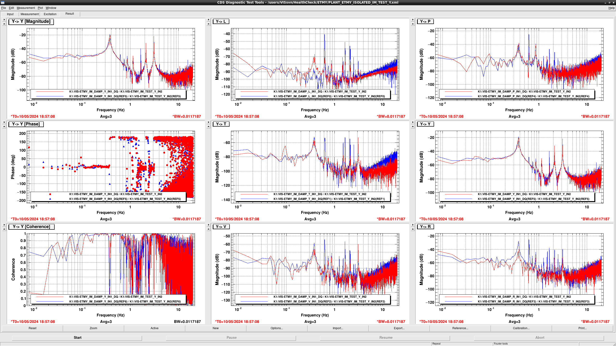
  • In TEST Y > Y, the DC gain got smaller slightly but In TEST Y > L,T the DC gain got larger because LVDT H3 is not working.
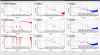
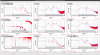
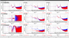
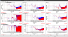
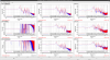
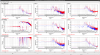
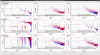
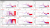
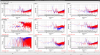
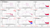
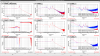
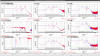
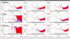
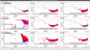
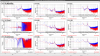
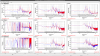
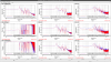
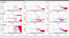
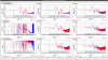
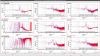
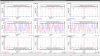
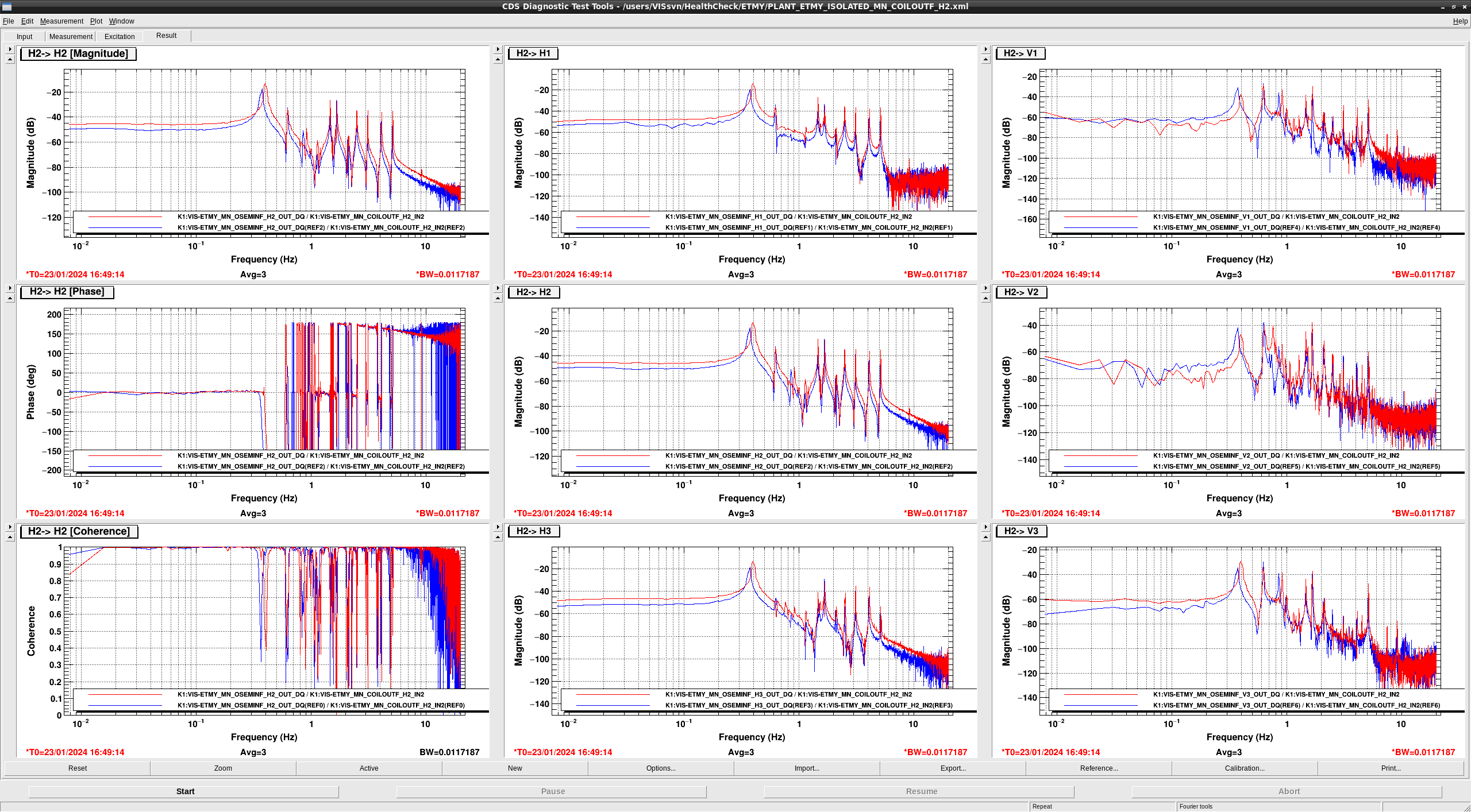
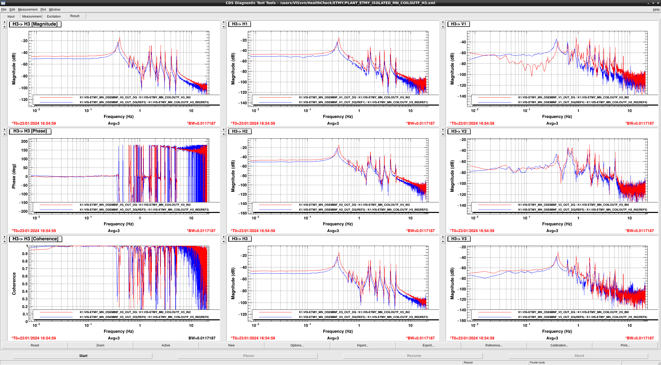
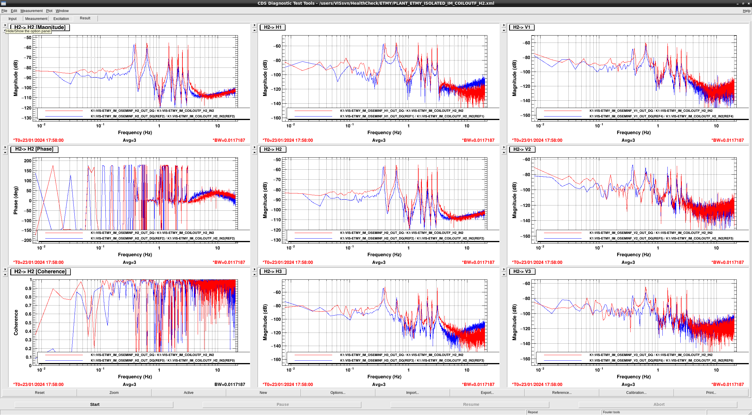
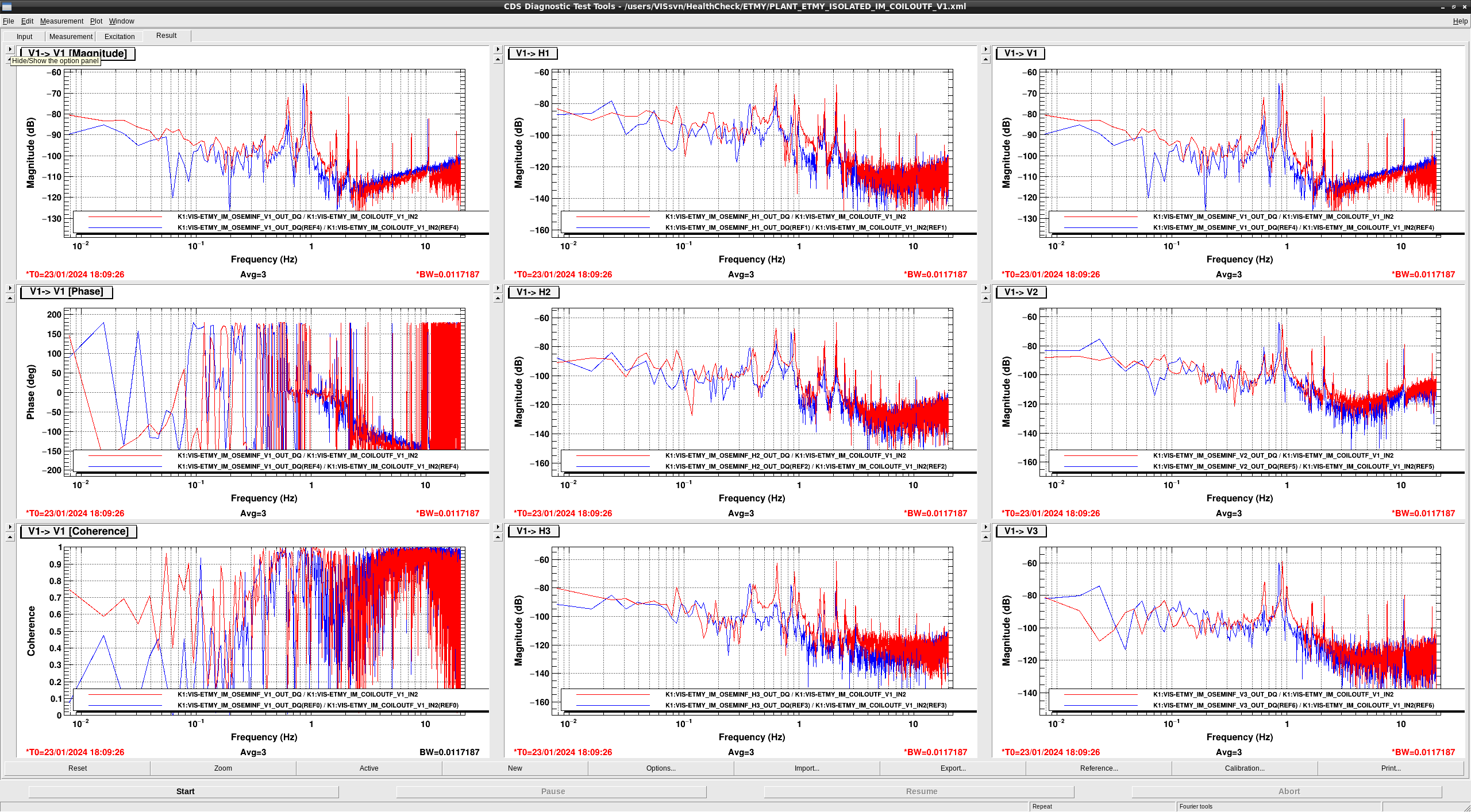
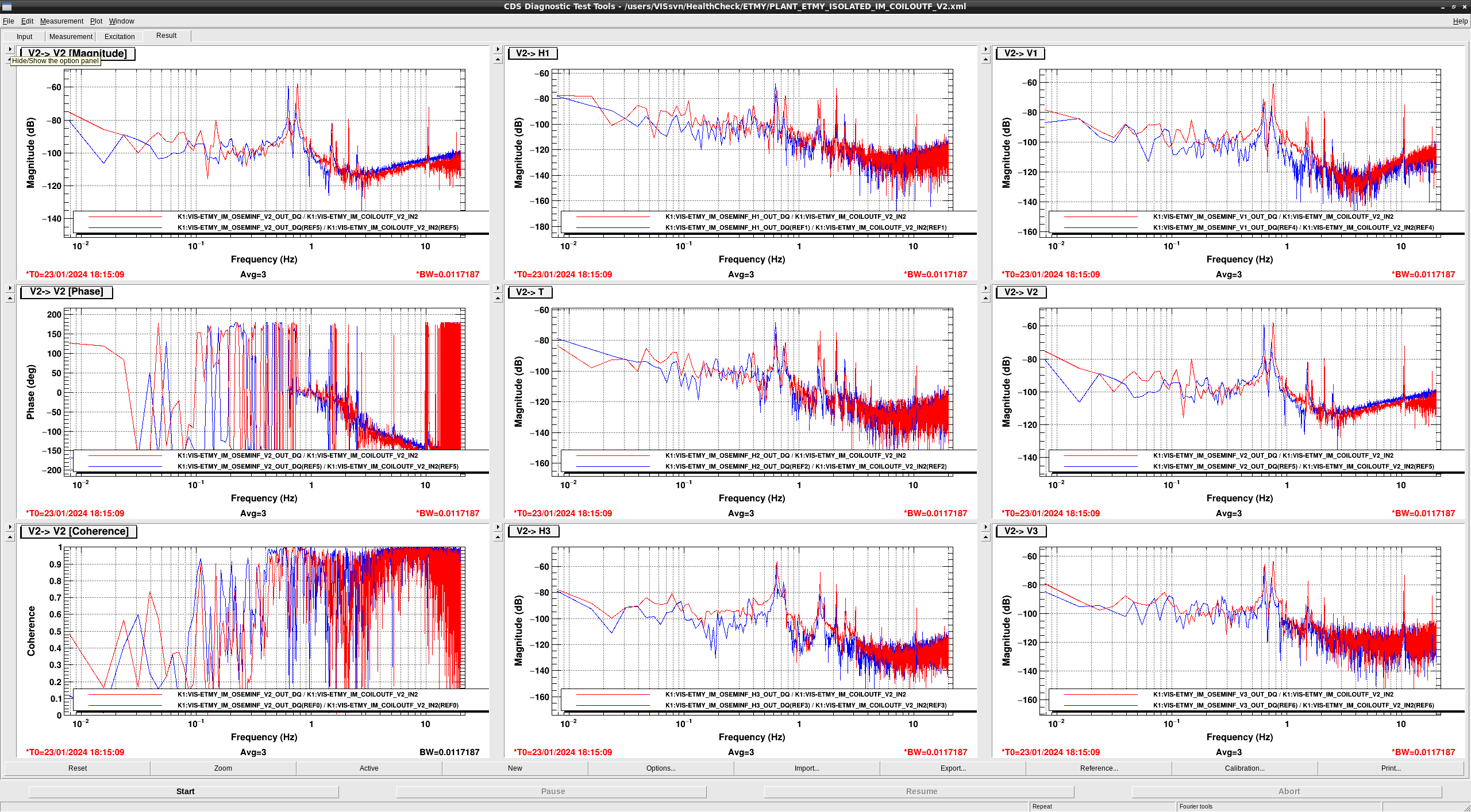
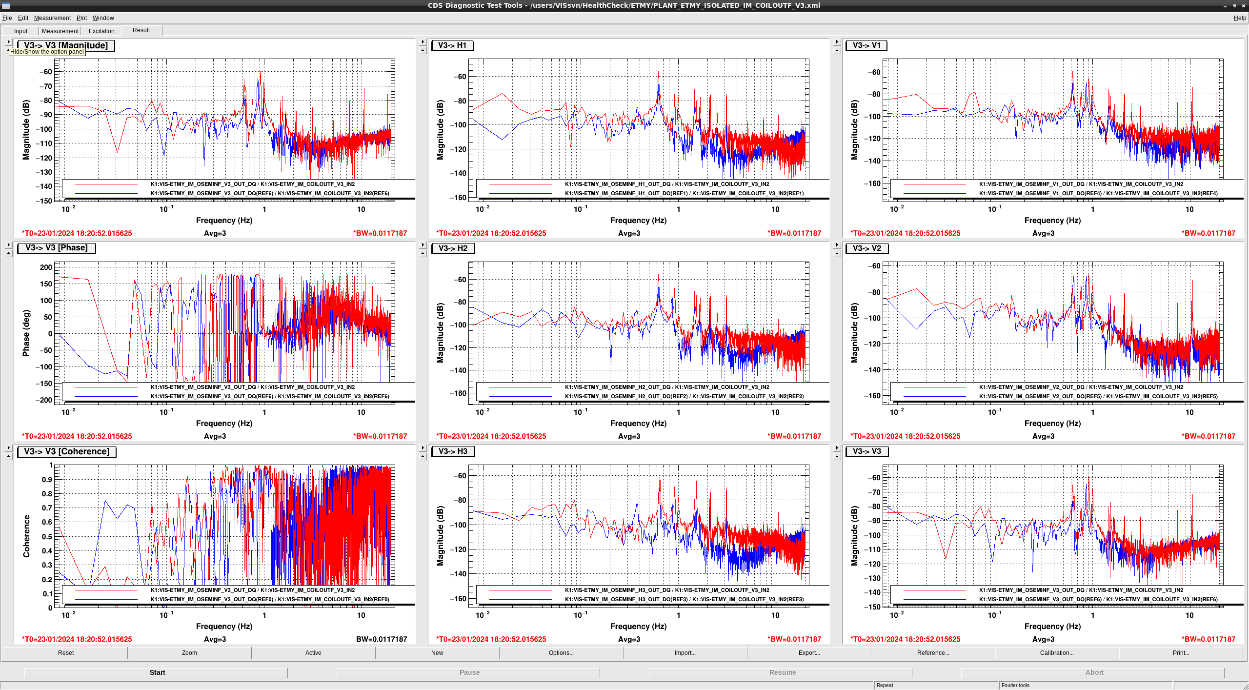
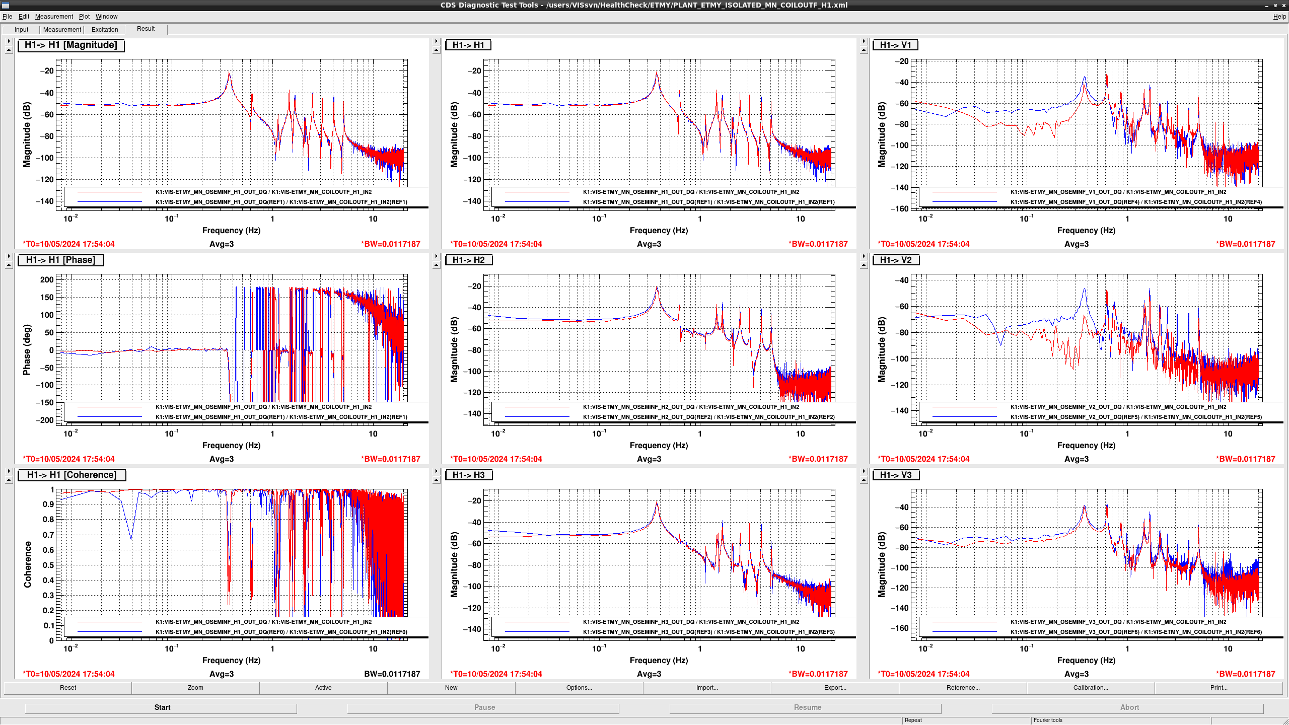
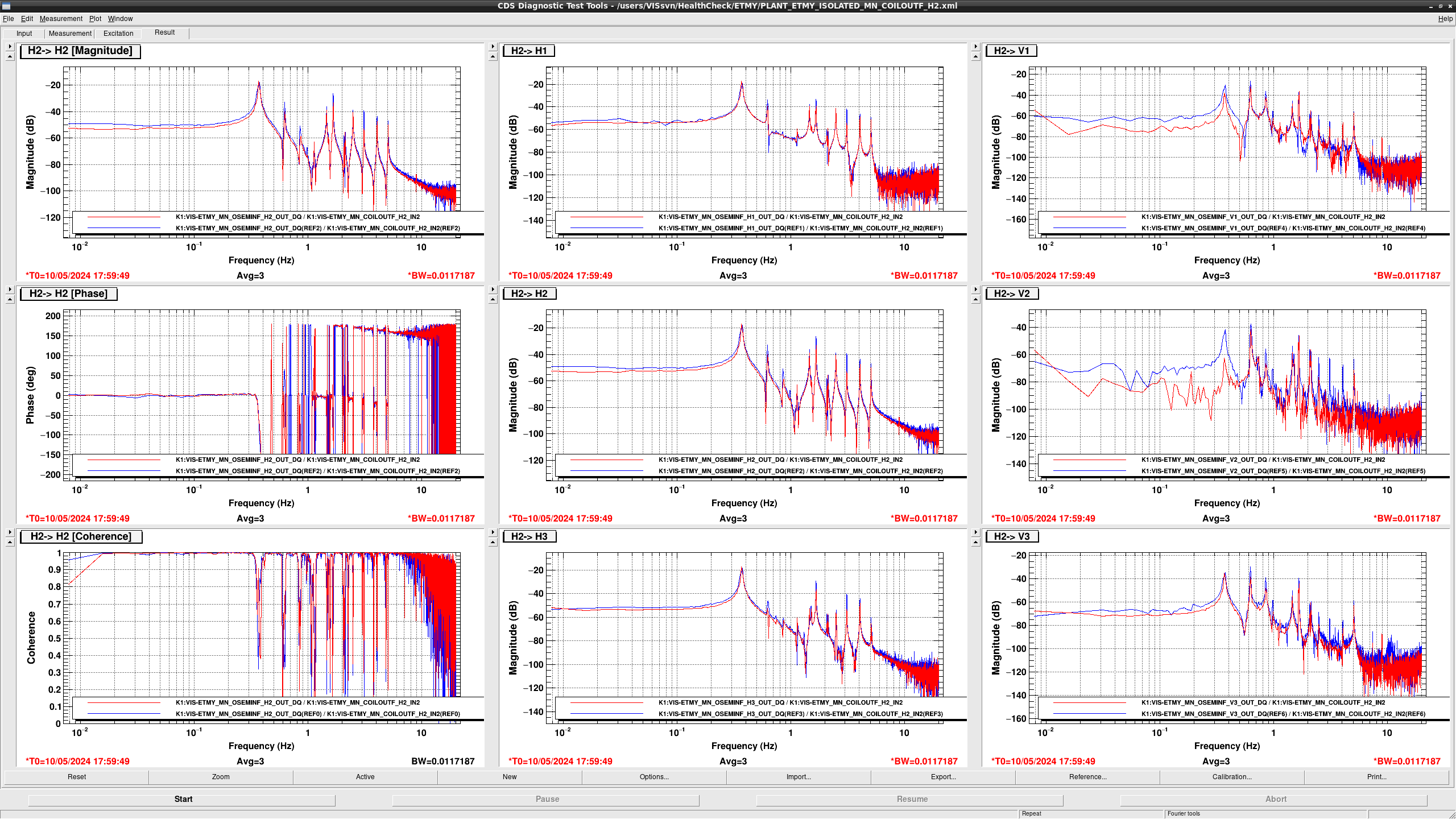
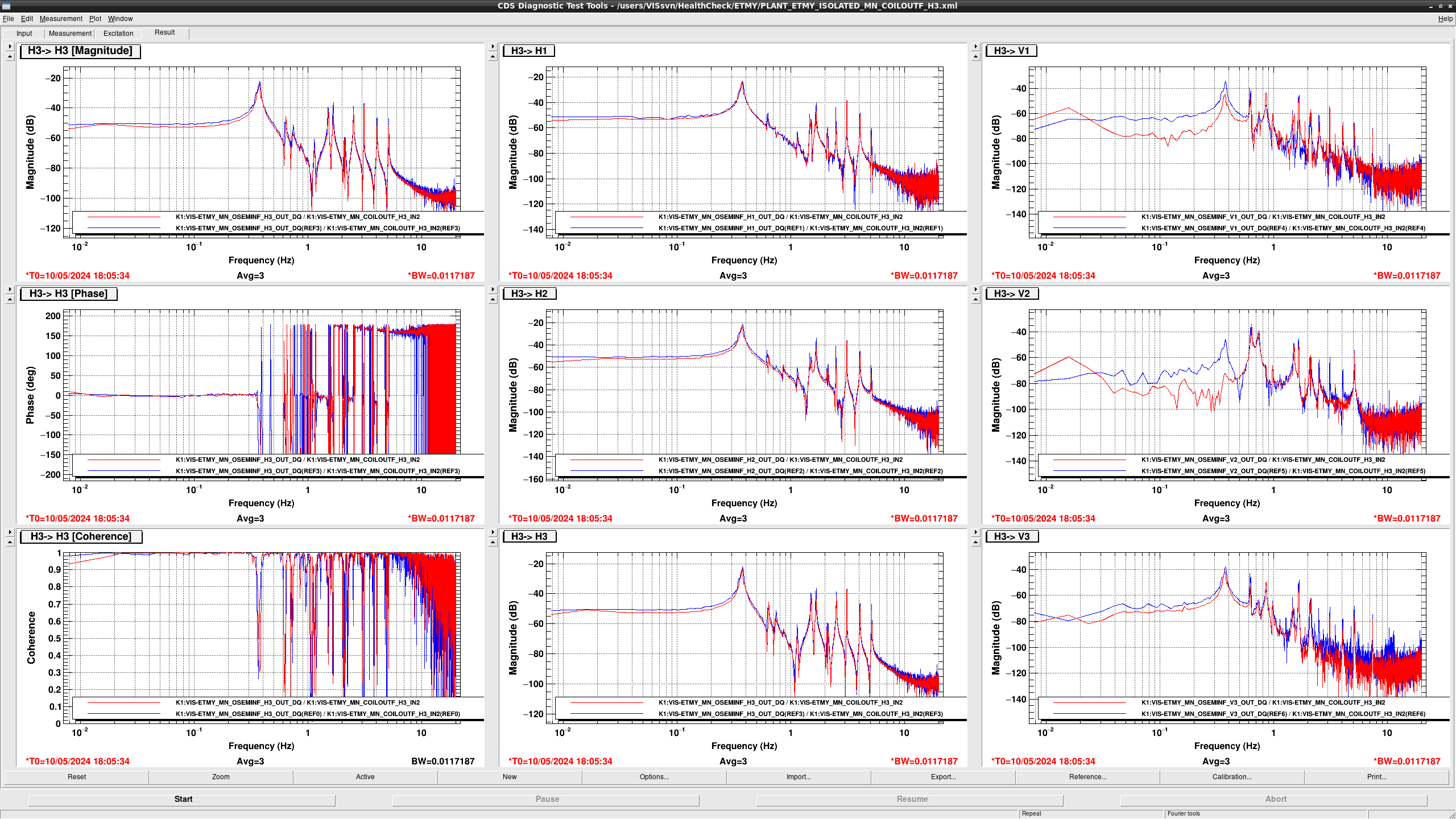
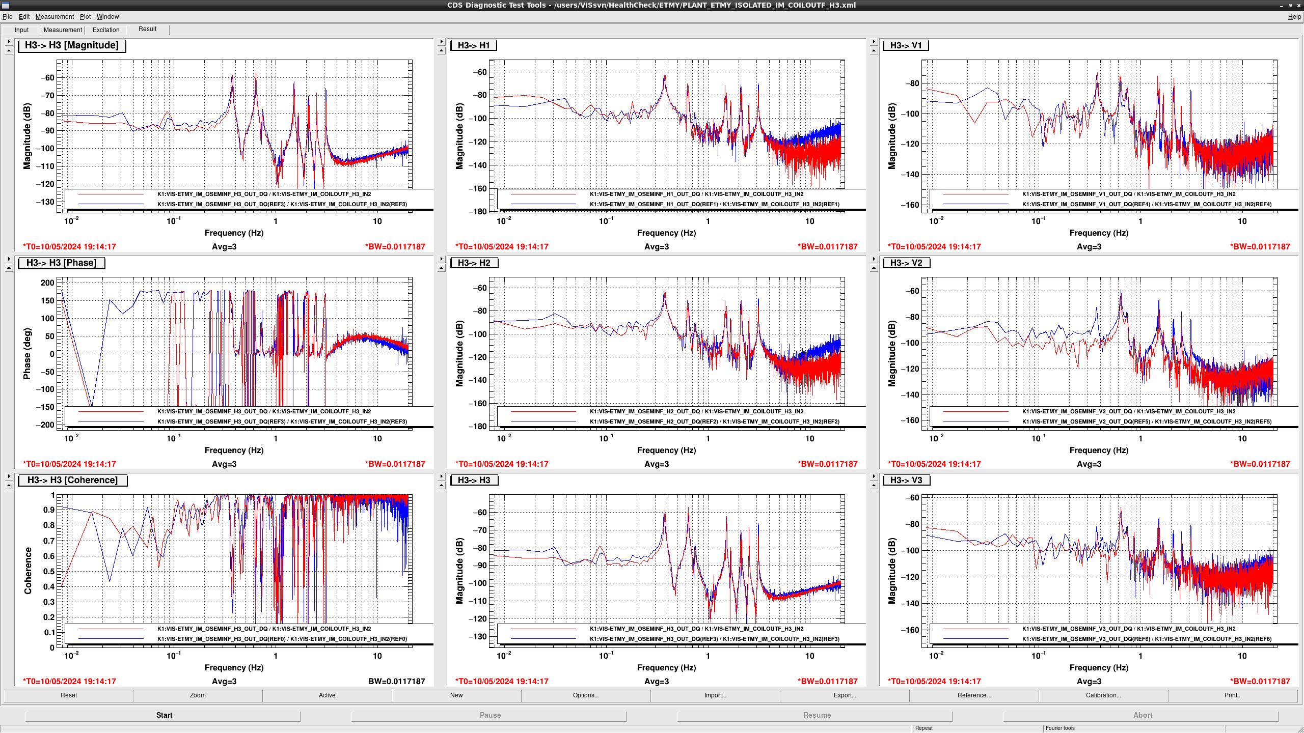
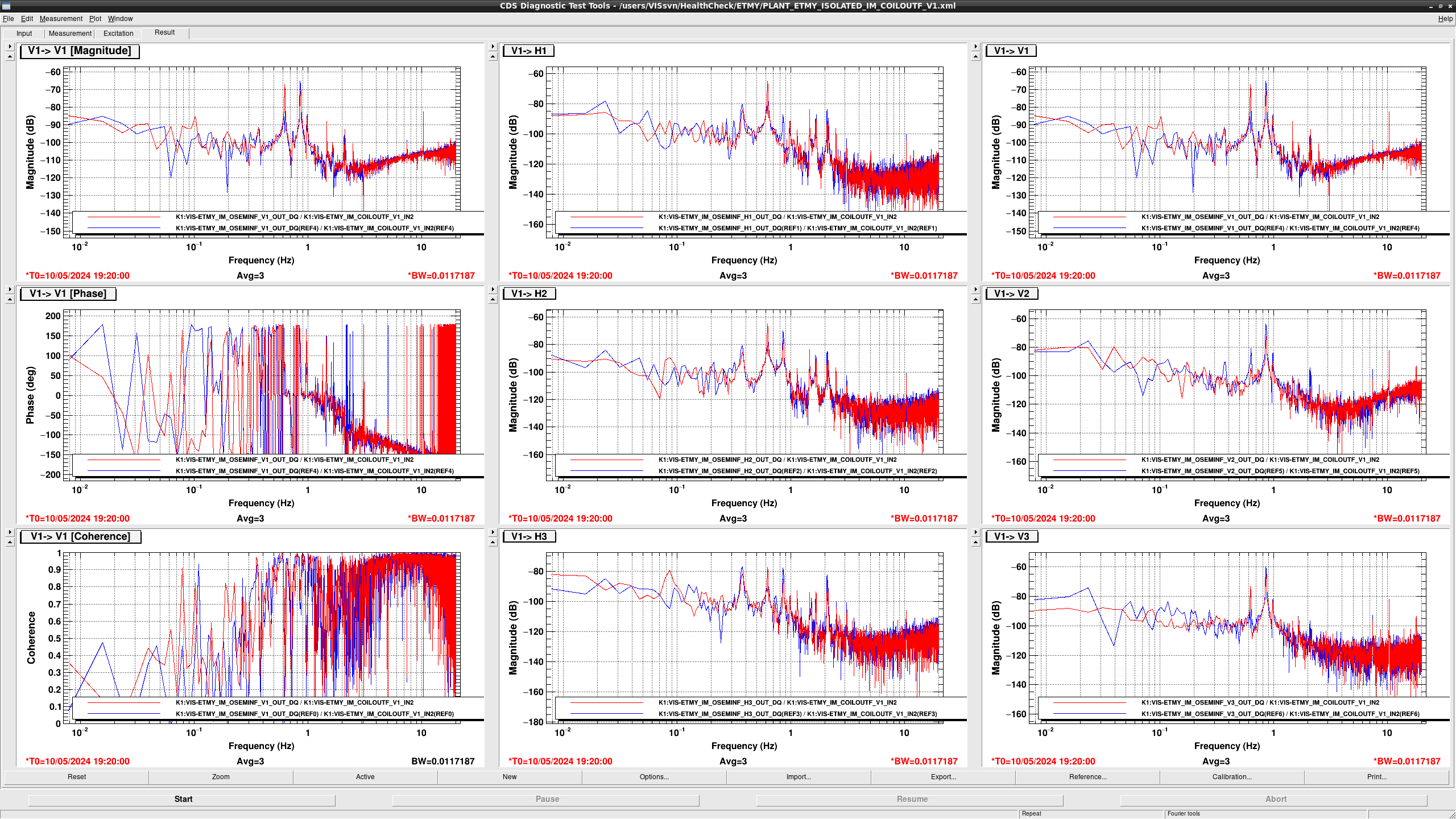
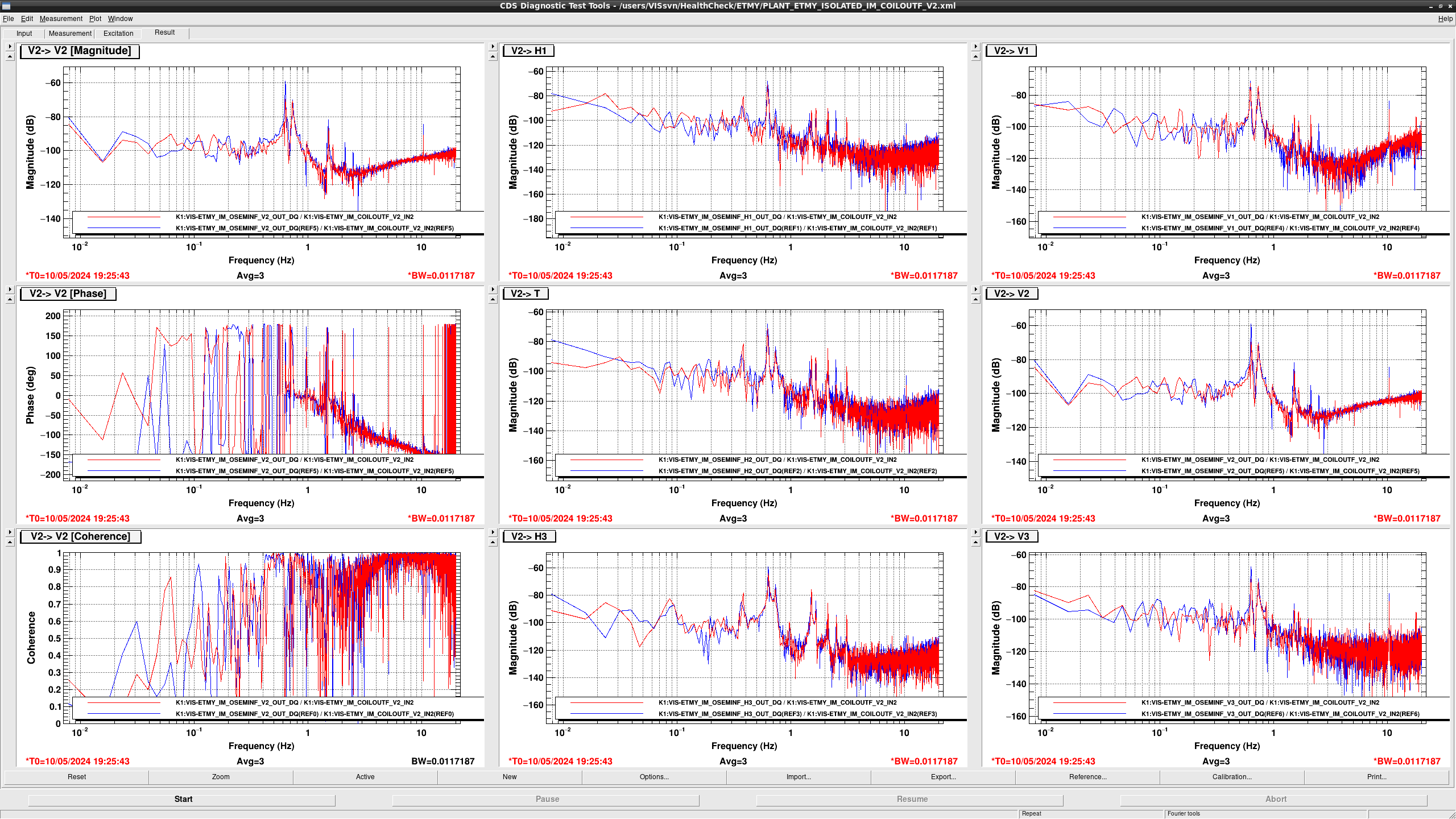
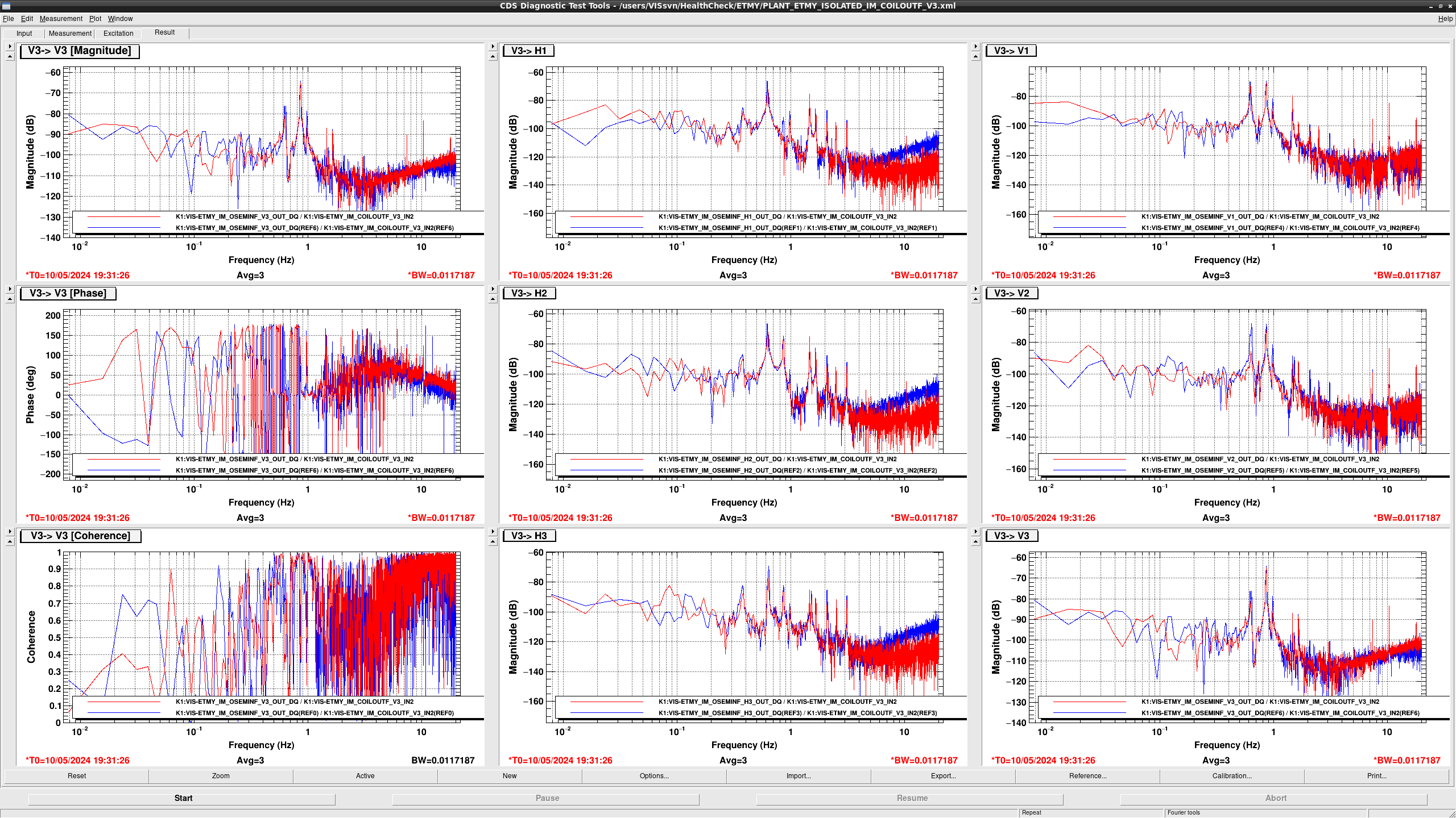
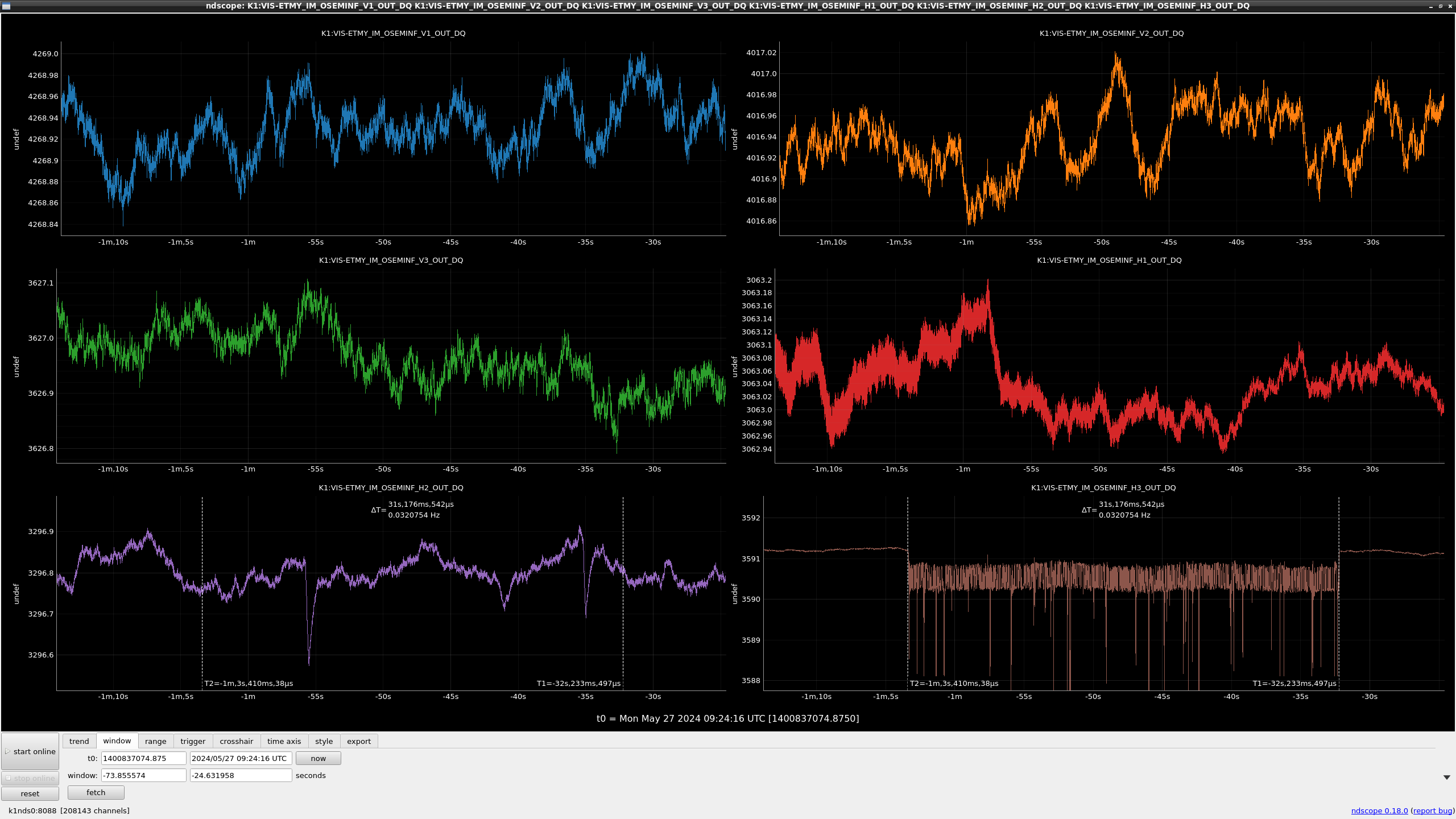
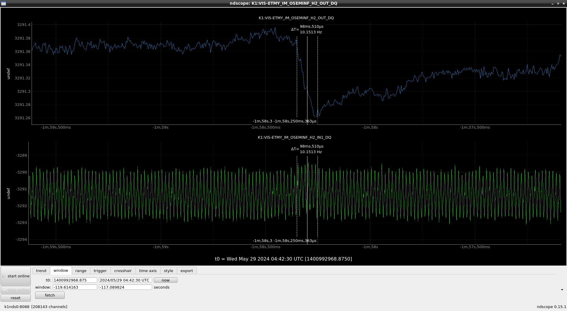
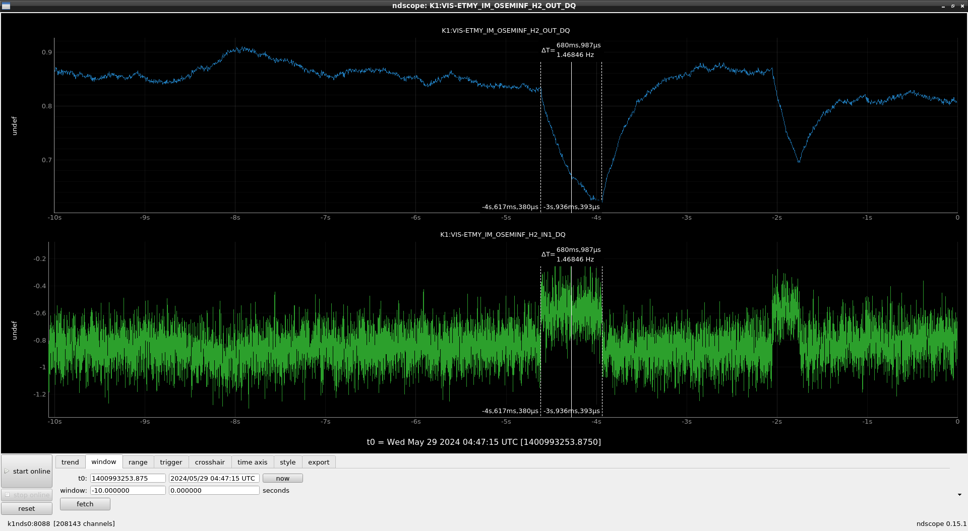
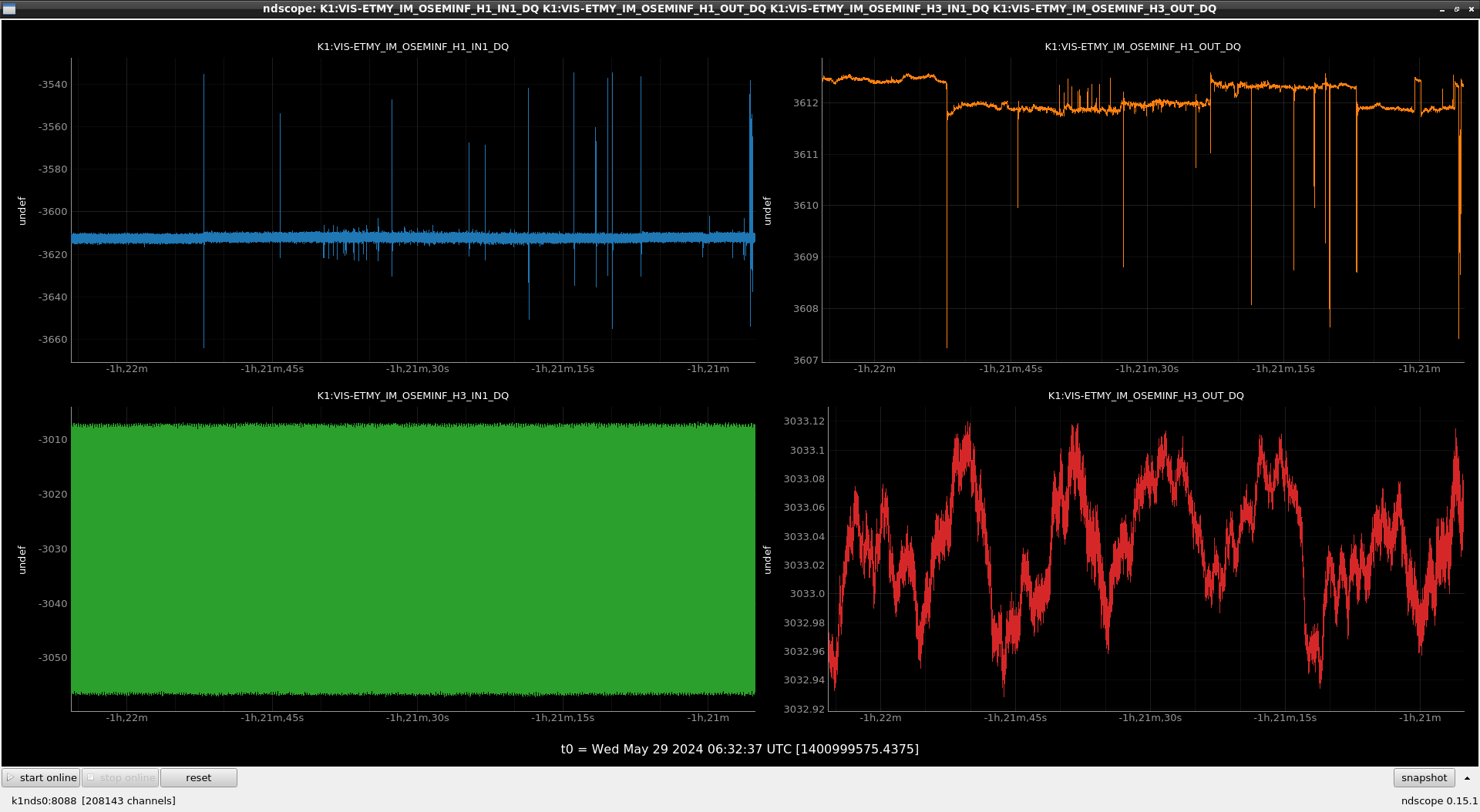
## MN and IM

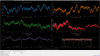
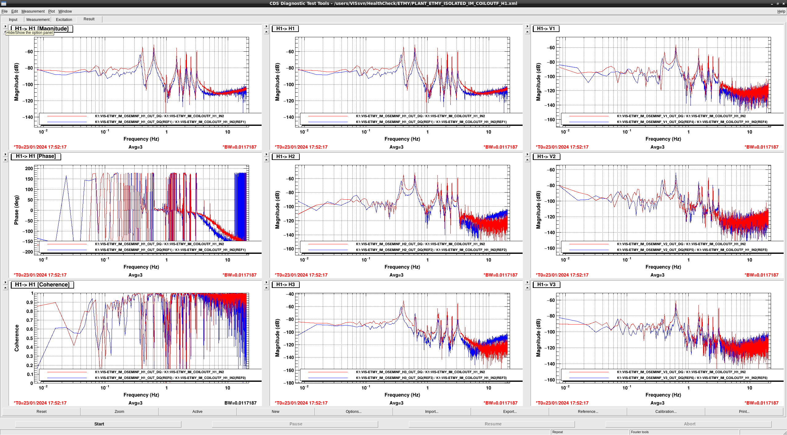
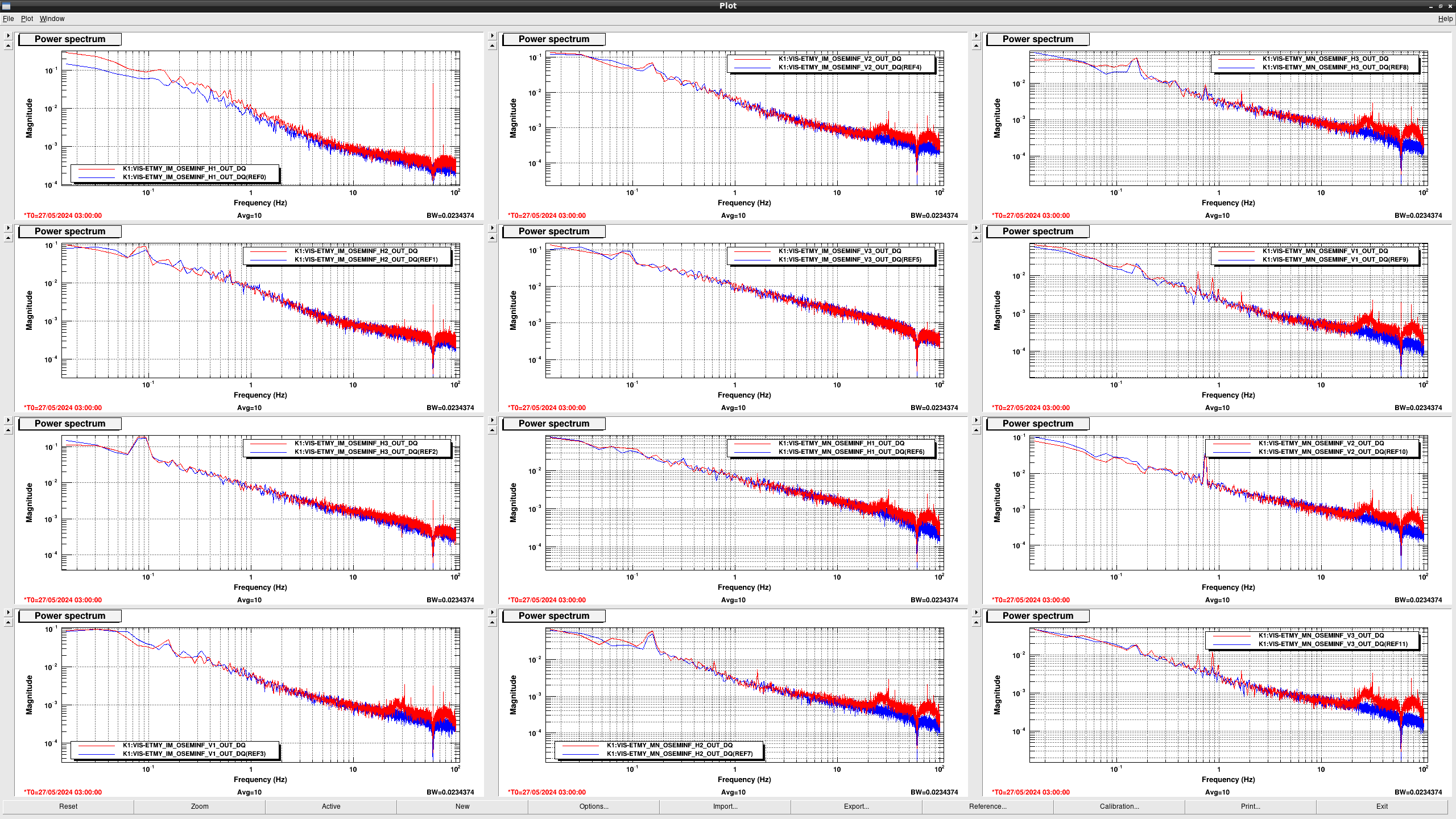
  • In COIL H1 > LVDT {H,V}{1,2,3}, their overall gains got larger and the lowest resonant frequecy got higher from 0.38 Hz to 0.40 Hz due to the temperature change.
  • In COIL H2 > LVDT {H,V}{1,2,3}, their overall gains got larger and the lowest resonant frequecy got higher from 0.38 Hz to 0.40 Hz due to the temperature change.
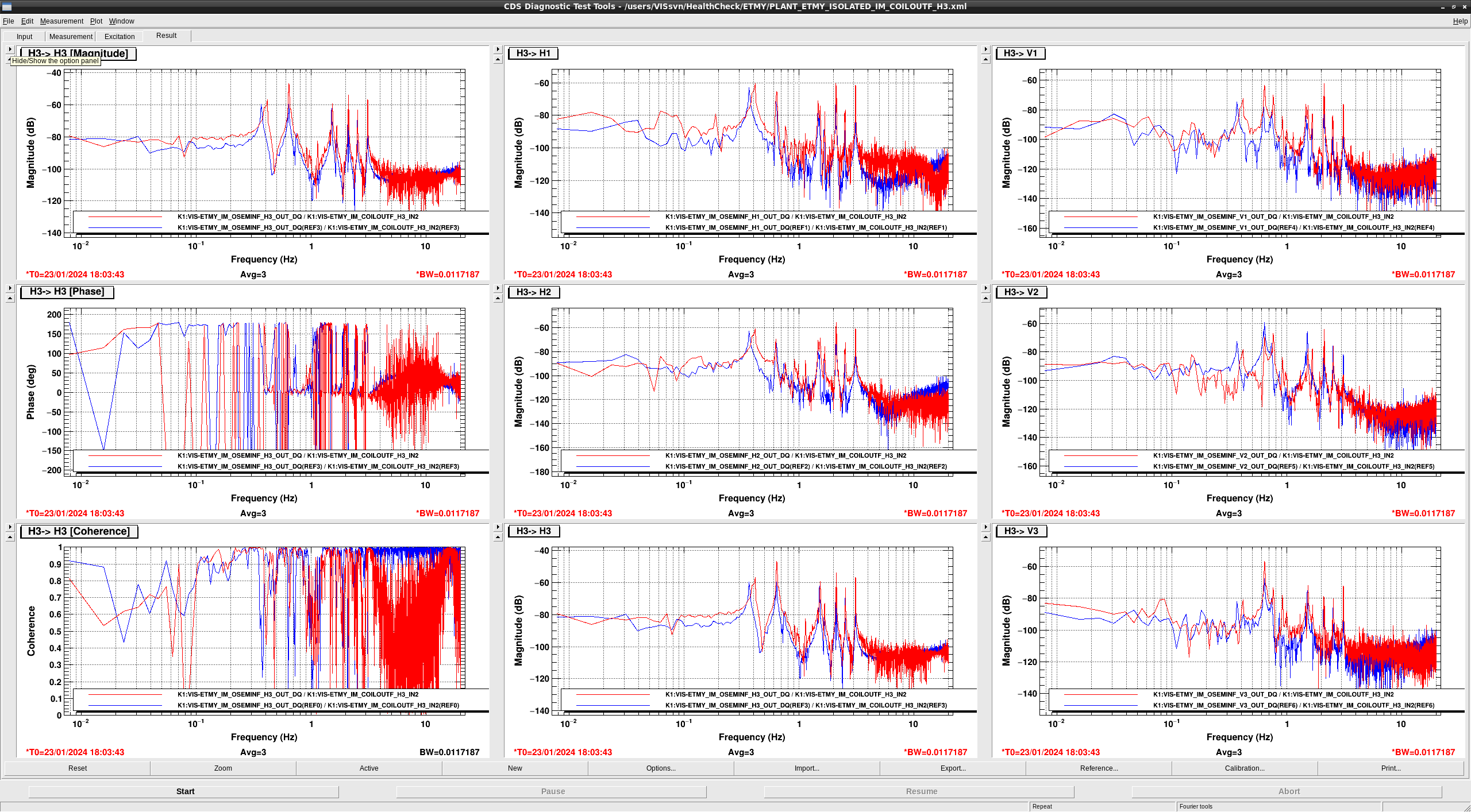
  • In COIL H3 > LVDT {H,V}{1,2,3}, their overall gains got larger and the lowest resonant frequecy got higher from 0.38 Hz to 0.40 Hz due to the temperature change.


Images attached to this report
Comments to this report:
takafumi.ushiba - 19:14 Monday 29 January 2024 (28457) Print this report

After the offload of F2 and F3 GAS, I remeasured the TF of GAS filters (fig1 - 5).
F0, F1, F3 and BF GAS seem to be healthy though some overall gain changes can be seen.
However, F2 GAS seems not healthy because high frequency above 2 Hz have low coherence, which might be due to rubbing somewhere.

Images attached to this comment
ryutaro.takahashi - 13:51 Monday 05 February 2024 (28506) Print this report

I offloaded the F2 GAS with the FR.

The height of the F2 keystone (2100um) was close to the mechanical limit (2230um) in the last health check. The height was offloaded to 1900um. The coherence of the transfer function above 2Hz was improved. F2 GAS became healthy.

Images attached to this comment
takafumi.ushiba - 11:26 Thursday 08 February 2024 (28550) Print this report

I checked ETMY BF LVDT with the same manner as reported in klog28451.
Results are as follows and BF H3 primary coil seems broken.

-Port 1-1(Primary coils): these should be around 26-28 ohms according to the documents

1-6 (H1): 28 ohms
2-7 (H2): 25 ohms
3-7 (H3): overflow (more than several Mega ohms)

-Port 1-4 (Secondary coils): these should be also around 25-26 ohms according to the documents

1-6 (H1): 25 ohms
2-7 (H2): 25 ohms
3-8 (H3): 25 ohms

takafumi.ushiba - 19:21 Thursday 16 May 2024 (29539) Print this report

I checked TFs if ETMY, which was measured on May 10th.
Some of TFs are strange, so we need to check them carefully.

Followings are what I noticed.

1. Vertical TFs of the tower changes a lot (fig7-11, 14, and 21-23). I would like to ask Takahashi-san to check them.
2. MNV TF changes a lot (fig26). It seems due to increasing the coupling from pitch DoF.
3. MNV3 TF gain becomes lower (fig35). Since currently MNV3 OSEM INF has again of -0.736, it might be due to this gain. This might cause MNV strange TF.
4. IMR TF gain becomes lower (fig39).
5. Sign of TM TF phases are changed (fig47-51). Dd we make a mistake dueing regluing the magnets?

Images attached to this comment
takafumi.ushiba - 13:08 Monday 20 May 2024 (29577) Print this report

I performed actuator and center balancing of ETMY to confirm strange MNV TF can be better by sensor/actuator decoupling.
Figure 1 shows the MNV TF after decupling.
MNV TF becomes healthy.

Also, I measured TFs from V1 and V3 coils (fig6: V1, fig7: V3).
Since the gain of V1 becomes smaller, the gain of TF is smaller than before but it is not problematic.
Also, gain of MN V3 is now same as the reference, so the smaller gain, which was measured previously, seems due to the gain change in DGS.

So, MN stage TF seems fine now.

What I did:
1. Photosensor gain (MN_OSEMINF_{H1,H3}_GAIN) was changed to minimize the coupling between MNV and MNP (fig2:before, fig3:current).
2. Actuator balance was performed for reducing V2P coupling (fig4: before, fig5:current).
3. V2Y actuator decoupling was performed (fig6)

Images attached to this comment
takafumi.ushiba - 19:47 Monday 27 May 2024 (29658) Print this report

Abstract:

I continued ETMY health check at IM stage.
Still we have several issues to be solved.

Detail:

Figure 1 shows TFs from IM roll excitation.
Though the gain of IM roll to IM roll at low frequency seems lower than before (not so clear due to low coherence), I could not confirm the reason.
Anyway, I hope it is not so problematic because IM stage doesn't use for daming roll motion of the suspension.

Then, I found three strage behaviours:
1. Small signal jump in IMH2 photosensor (fig2), which seems ADC glitches because the jump at raw input is just 1cnt or so. So, it doesn't seem problematic.
2. Large glitcies in IMH3 photosensor (fig3). I have no idea what they are at this moment.
3. Photnsensor noise at high frequency (fig4), which cannot be seen if suspension is in SAFE state (fig4: blue:SAFE, red:ISOLATED). After several investigation, I found the noise has large coherence with ACC local servo feedback (fig5). So, I modified the ACC local servo. Old servo has an UGF of 20 Hz and phse margin is only 30 degrees. Since ACC is used only below 0.1 Hz, I changed UGF at 3 Hz and phse margin is about 70 degrees (fig6). After these modification, photosensor noise at high frequency are disappeared.

Images attached to this comment
takafumi.ushiba - 8:36 Tuesday 28 May 2024 (29662) Print this report

I made a mistake for fig3.
Attached figure should be fig3 I mentioned in original post.

Images attached to this comment
takafumi.ushiba - 19:37 Wednesday 29 May 2024 (29674) Print this report

I confirmed IM H2 glitches comes from ADC glitches.
Figure 1 and 2 show the IM H2 signals when the cable at AA was connected and disconected, respectively.
In both case, the glitches can be seen in the signals, so the problem is between AA to DAC, not inside the vacuum chamber.

I also checked the reason of IM H3 glitches.
Figure 3 shows the IMH1 and IMH3 signals when IMH1 and IMH3 cables were swapped at the satellite box.
Since the glitcy channel was changed to IMH1, the glitch source should be chamber side.

After that, I swapped IMH2 and IMH3 cables at feedthrough port.
Then, I could not find any glitches on both signals for one hour (fig4), though there are small glitches in IM H2 signals coming from ADC glitches.
In addition, even after recovering the swapped cables, glitches seem disappeared for more than 3 hours.
I will investigate further if glitches will happen again.

Images attached to this comment
shoichi.oshino - 14:24 Thursday 30 May 2024 (29693) Print this report
I checked EY IM H2 and H3 glitches on 5/27 by using Omicron.

There are steady glitches in the H2 signal.
Ushiba-san confirmed that these glitches are caused by the ADC.
On the other hand, the H3 signal shows a non-stationary glitch distribution.
Since 11:00 UTC, EY suspension has been kept in the ISOLATED state. The change in glitch distribution does not seem to depend on the guardian state.
Images attached to this comment
takafumi.ushiba - 8:59 Thursday 06 June 2024 (29753) Print this report

There seems no glitch in IMH3 photosensor for a week.
I'm not so sure if it is recovered or not but there seems no need to touch the suspension at this moment.

Images attached to this comment
shoichi.oshino - 15:22 Monday 10 June 2024 (29816) Print this report
I also checked photosensor data from 5/30 to 6/6 by using Omicron.
IMH3 didn't have significant glitches.
The ADC related glitches were still present on IMH2.
I also checked the IMH1 photosensor, it had more glitches than the H3 but compared to the H2 almost fewer glitches exist. It does not seem necessary to notice at this time.
Images attached to this comment
Search Help
×

Warning

×