[Capote, Nakano, Ushiba, Hirose]
We continued to have challenges moving to DC readout today, and we determined the problem is related to unstable alignment control. To solve this problem, we spent the rest of the day working through the many steps required to set up alignment sensing and control using the wavefront sensors.
Here is a summary of the alignment control work done today:
- I changed the output matrix for the arm DOFs to be a true DHARD/CHARD diagonalization. According to the wiki, the mirror radii of curvature are all the same, so these values should be +/- 1 (I followed this diagram in the DCC)
- Then, I set out to determine the appropriate sensing for each DOF. I started with DHARD P. I drove a 8.125 Hz line from the "DHARD_P_SM_EXC" point. This was when no ASC loops were closed, but the IFO alignment was good. The DHARD P results indicate that AS QPD1 RF17 Q is a good sensor. I updated the input matrix for DHARD accordingly (1 for AS QPD1 RF17 Q)
- On second thought, I am not very happy with the SNR of these results, and I am concerned about the phasing of the WFS. I would like to check the phasing of all WFS and then rerun these sensing matrix measurements
- I also want to check on the DC centering loops for the wavefront sensorsa nd make sure that they are running so we get a decent centered signal
- I have not yet had the same success determining the appropriate sensing for DHARD Y
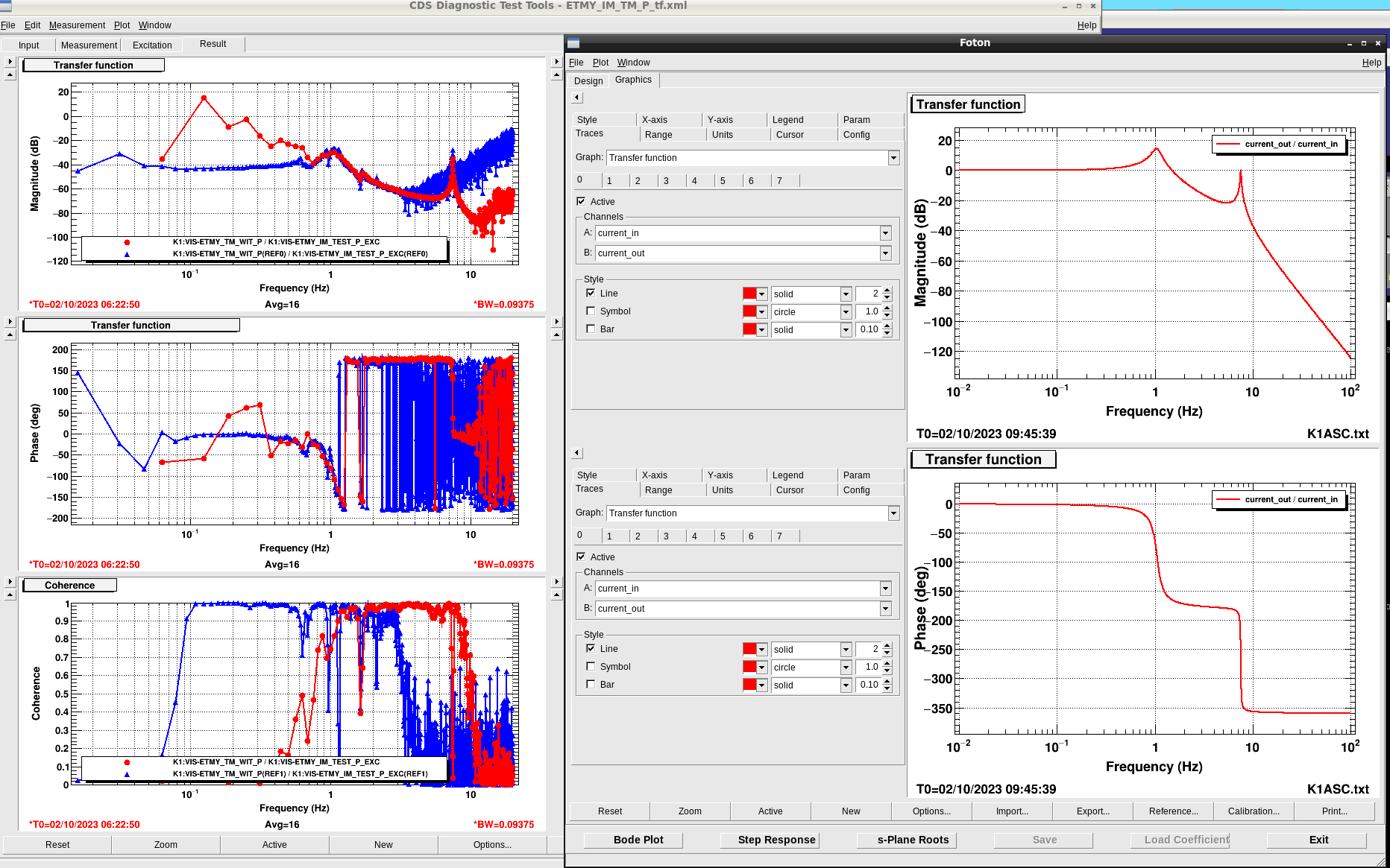
- I measured the suspension transfer functions of the IM to TM in pitch and yaw using ETMY
- I struggled to achieve decent coherence from 0.1 to 10 Hz without saturating actuators, so I split the measurement into two sections. The colors show which measurements correspend to which coherences
- The first two attachments show the suspension plant open loop gain measurements alongside with the foton model I designed from the measurement
- Based on the measurements, I designed a model plant that I put in all HARD loop filter banks for ease of filter design
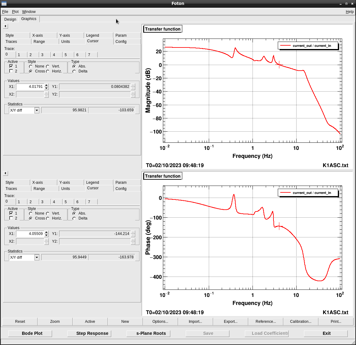
- Based on the measured plants, I designed a loop compensation for DHARD and CHARD in pitch and yaw. The loop design assumes we move away from a DC coupled oplev damping and instead offload to the MN stage using a low bandwidth integrator. The ASC control will feedback to both the MN and IM stages with the MN integrator. The design is a simple "gentle" plant compensator (i.e. not an exact plant inversion), with a low pass cutoff and a gain to set the UGF. The design UGF of the pitch loop is 10 Hz with phase margin 31 deg, and the UGF of the yaw loop is 4 Hz with phase margin 36 deg.
- The second two screenshots show the loop design for the pitch and yaw hard loops. The design is the same for CHARD and DHARD
- While trying to get decent measurements of the sensing matrix I changed the whitening filters of the AS WFS to be two stages of whitening with 6 dB gain. I also changed the whitening filters on the test mass coil drivers for the IM stage to be analog low pass ON (state 2)
- There are some details to be worked out regarding the offloading of the oplev signals before the ASC is engaged. Masayuki has done this work and will comment his results
- There is also some work to be done regarding the way the length signals are offloaded to each stage of ETMX. The current way it is done prevents us from properly engaging the IM and MN offloading that we would like for the ASC signals. Masayuki is also working on this and will comments his results.
Much of this is still a work in progress. We have been holding in down to wait for an earthquake to pass.


