Ushiba, Hirose
In this work(klog24690), we found that ADS from POP to IMMT1 was taken many times. And the ADS couldn't find a good position as other of IMMT1_trans.
We tried the beam position control (BPC) of PR2 instead of ADS so that to plan to fix the beam locally with the center of PR2 as one reference point.
Preparation.
First, we did the initial alignment. Next, We turned on WFS for ETM and BS, turned on ADS from POP to IMMT1 for better PRFPMI alignment.
The day before, we set the offset of the error signal of ADS_IMMT1_POP to the position where the transmitted light was better, so we put null before starting the work and stopped the control at that good position.
What we did.
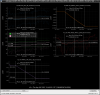
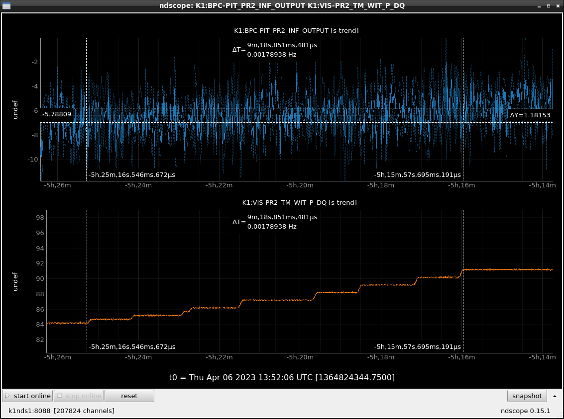
- Tried feedback control from the transmitted power signal of POP to IMMT 1 with PR2 oscillating.
This is with ADS on IMMT 2, PRM and BS, and WFS on ETM and BS turned on, so when IMMT 1 is moved, the entire optical axis is following.
However, upon testing, we found that IMMT1 has to be moved A to set the error signal to 0.(FIg1) - Next, we tried to control POP to feed back to PR3 with PR2 oscillating.
Likewise, the entire optical axis is tracked by WFS and ADS when trying the control.
However, although the error signal of BPC became smaller, the transmitted light power went down due to over tilting of PR3 by the control in the middle of the process.
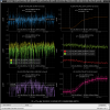
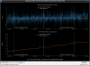
Also, since it is also in the GR optical path, the transmitted power of the GREEN has also dropped, so if we finish this control, we will need to improve the alignment of the GREEN.(FIg2) - Finally, we tried a BPC from POP back to PR2 with PR2 oscillating.
This suggested that a local BPC to PR2 would change the optical axis of PRCL, and IMMT2 located in the gouy phase similar to PR2 could correct the overall optical axis by ADS.
I checked the sign reversal of the filter in the PIT direction in preparation for the control.(Fig3) we have yet to check for YAW.
Next time we will try the continuation of this and actually turn on the control.
NOTE
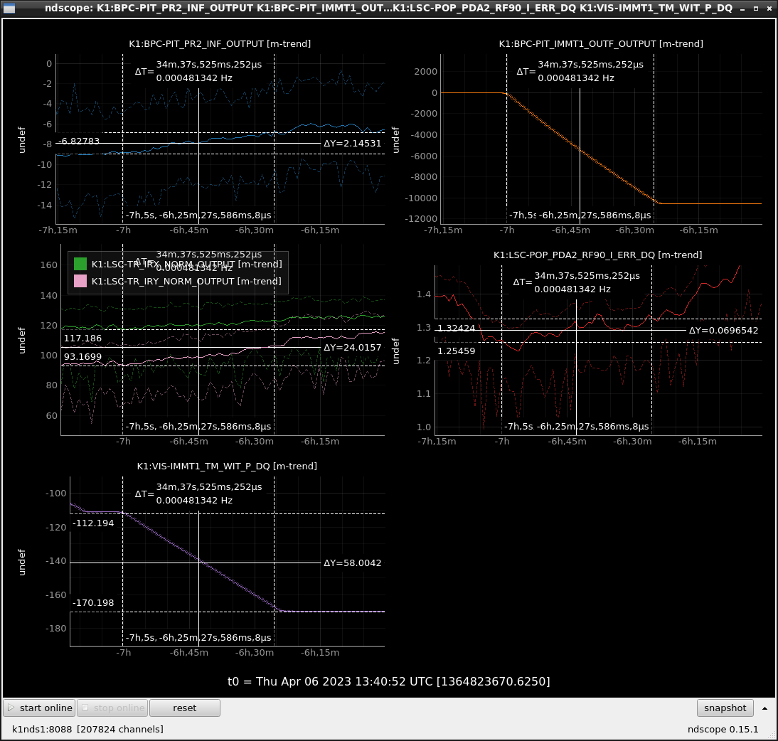
How to set up BPC.(Fig4)
- Set the oscillator frequency and ramp time. (In this case, the frequency is based on the PR 3 frequency that was originally included.) Assign 1 to sin and cos. Set the click gain so that the SN ratio is greater than 10 while checking the power spectrum of PRCL(K1:LSC-PRCL_OUT_DQ).
- Set a bandpass filter to remove other bandwidths of the signal from the POP, other than the frequency set by the oscillator.
- Measure the demodulation phase and this time set the phase so that the I phase is at its maximum.
Since the control frequency is lower than 0.1 Hz this time, we set for the filter of the demodulated signal as a low pass at 1 Hz and a combo filter. This combo filter is the role that notches several times at equal intervals starting at 5 Hz so that removes the beat signal at the PIT and YAW frequencies, respectively. The output signal of the filter here is the BPC error signal. - Insert a 1 in the matrix to send the signal to the mirror to be fed back by the BPC.
- Set the BPC filter to OUTF.
