Ushiba, Hirose, K. Tanaka
## Abstract
We are now facing two problems with the ASC: first, when we align PRFPMI with the ASC, the transmitted power of the Y-arm cavity is about 30 percent less than that of the X-arm cavity. The difference in transmittance of each arm cannot explain this difference. On the other hand, since the amount of transmitted light is quite different between yesterday and today, but the amount of reflected light is not so different, it may be that the optical axis from the resonator to the PD on the transmission side has changed when the alignment is better, and the light is clipped somewhere.
The other problem is more severe than the first one. When we add a DARM offset to do a DC readout, the AS WFS signal will have an offset on it. The cause of this WFS offset may come from the carrier TEM00 that appears on the AS side due to the DARM offset, and since the DC readout keeps the transmitted power in the OMC constant, any change in the amount of the DARM offset will change the amount of offset on the AS WFS. The amount of offset also changes. In other words, adjusting the DARM causes the alignment to move, and adjusting the alignment causes the DARM to move. We cannot use ASC with AS WFS for DC readout. So far, we have not found a way to deal with this offset...
## What we did
### The difference between the Y-arm transmitted power and the X-arm transmitted power when engaging full ASC for PRFPMI
- As shown in the previous log, for all degrees of freedom of the interferometer, when ASC is applied, the amount of transmitted light in the Y-arm is about 30% lower than the amount of transmitted light in the X-arm.
- We computed the transmittance of each arm to obtain the ratio of the transmitted light intensity. According to our calculations, we found that the ratio is smaller than 10%. (See Ushiba-san's log for detailed calculations.) In other words, The only difference in transmittance of each arm cannot explain this difference.
- We suspected an alignment to the Y-arm. To adjust this alignment, we adjusted the following degrees of freedom individually to see if the transmitted power would be better.
- COMMON ETM
- DIFFERENTIAL ETM
- COMMON ETM and DIFFERENTIAL ETM
- BS
- PR3
- PRM
- ITMY
- When we moved the degrees of freedom of COMMON ETM and BS and improved the Y-arm transmitted power, the X-arm transmitted power also improved, and the difference between the two did not narrow. Even when the amount of transmitted light improved, the shape of the REFL beam spot was split, resulting in poor alignment overall. However, both transmitted powers seemed unchanged when we moved the other degrees of freedom.
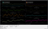
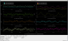
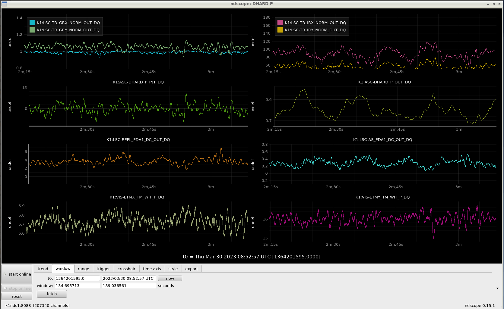
- Once the PRFPMI lock was down, we re-aligned the alignment, locked PRFPMI again, and applied ASC. At this time, both IR transmitted power became smaller than before. On the other hand, the GR transmitted power became larger than before. Furthermore, the reflected power and the power at AS were the same (Before re-lock PRFPMI:Fig.1, after: Fig.2). When the alignment improved at ASC, the optical axis between the cavity and the transmitted PD changed and may have been clipped somewhere.
### try DC readout with ASC
- After the above investigation, we tried a DC readout with ASC applied. However, while applying the DARM offset and waiting for the OMC to lock, the alignment worsened steadily, and finally, the PRFPMI lock went down.
- After investigating the cause, we found that the alignment was getting worse from the moment when we applied the DARM offset.
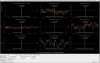
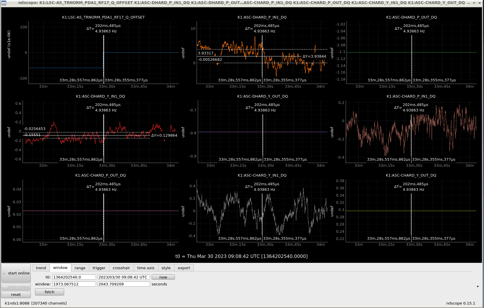
- Therefore, we applied the DARM offset with the ASC turned off and checked the error signal of the ASC. As a result, we found that the DIFFERENTIAL ETM degree of the freedom error signal, the AS WFS signal, had a significant offset (fig. 3). This may be because the DARM offset increases the TEM00 of the carrier on the AS side. The beat between the TEM00 of the carrier and the TEM10 of the sideband is the offset of the DIFFERENTIAL ETM signal (the beat between the TEM10 of the carrier and the TEM00 of the sideband).
- Any change in the amount of the DARM offset will change the offset amount on the AS WFS. The amount of offset also changes. In other words, adjusting the DARM causes the alignment to move, and adjusting the alignment causes the DARM to move. We cannot use ASC with AS WFS for DC readout.
- So far, we have not found a way to deal with this offset...