[Akutsu, Miyoki, Takahashi, Sato, Ushiba(home)]
Purpose of this work: make a monitor for the motion of SR2 and OMMT1 separately.
- The ideal try is to measure the beam profile and decide the lens focus length and distances with each component. However, the beam strength is too weak.
- So, we anyway decided to set two QPDs and check how well or how worse we can sense SR2/OMMT1 mirror motions.
Today's "Temporal" optics setting:
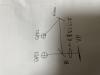
- Ushiba-kun provided us with a rough sketch of the optical setting on the OMMT2 trans-optical table. (photo.1)
- Previously, Akutsu-kun set QPD1, and set the beam position at the QPD1 center by using micrometers of the QPD mount. Also QPD2 was set at proper position.
- Akutsu-kun attached an optical window on the OMM tank. So, the beam position shift is expected. Akutsu-kun readjusted the beam position at the QPD1 center.
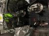
- Miyoki set a 2-inch 50/50(for S polarization) beam splitter and a 2-inch mirror as the photo.2. Although the OMMT2 trans beam power is so weak, I could recognize its beam spot on an IR sensor card with the "IR viewer with an x1 multiplier lens". While the IR viewer with an x2 multiplier lens scarcely enabled us to recognize the beam spot on the IR sensor card. So please use the former IR viewer. So, I believe that the beam spots on the BS and the mirror are set around the center, judging from the IR viewer images(no photo). In addition, the 2-inch size is wide enough to handle the OMMT2 trans beam.
- I set the QPDs' gain at high.
- Obeying Akutsu-kun's instruction, I adjusted the horizontal/vertical position of QPD1 to obtain the centrally aligned beam that should provide the same amount of values of "OMCO_MADC3_EPICS_CH24~27 for QPD1". While I adjusted the pitch/yaw of the mirror and the horizontal/vertical position of QPD2 to obtain the same amount of values of CH28~31 for QPD2. CH24~27 and CH 28~31 correspond to the raw data from each QPD1/2 segment. In this step, the rough values were ~-60 ~ -70.
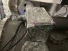
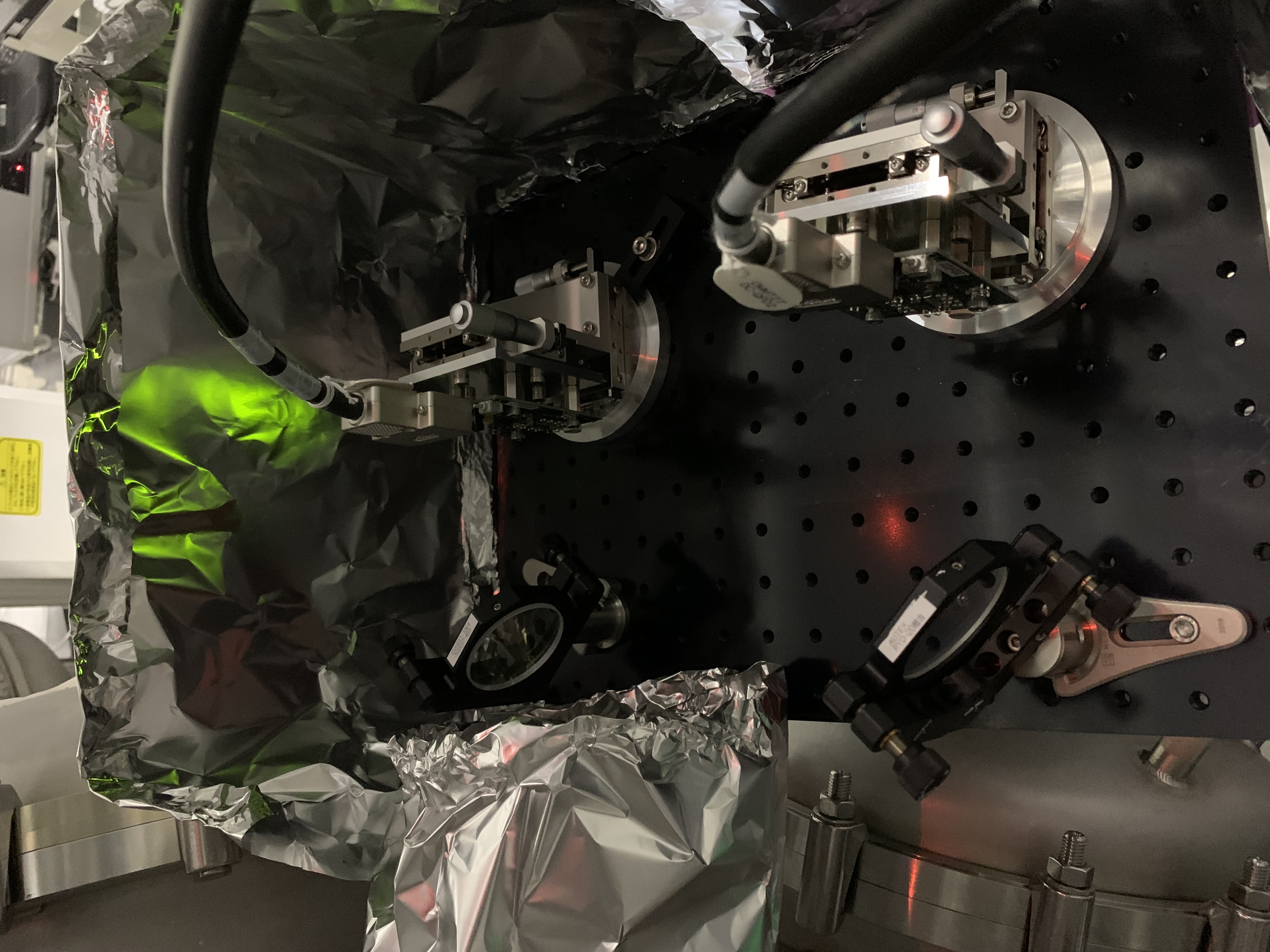
- Because I was warned about the influence of the ambient light to QPDs by Akutsu-kun, I constructed a temporal aluminum foil cover as the photo.3.
- Although the covering was not perfect, each value decreased to ~ -30 ~ -40. When I shielded a beam to QPD2, the values became ~ -4. So the ambient light's offset is about 50%!
Note: This is a temporal setting. We should find a good optical setting or signal combination.