w/ Miyoki, Yokozawa et al.; cont'd from 22604, 22745, and 22844.
Summary
Now we can somehow read one the the OMMT2 trans signals (OMMT2T), while software and middleware preparation including their RT models and MEDM screens should be done later.
Details
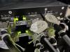
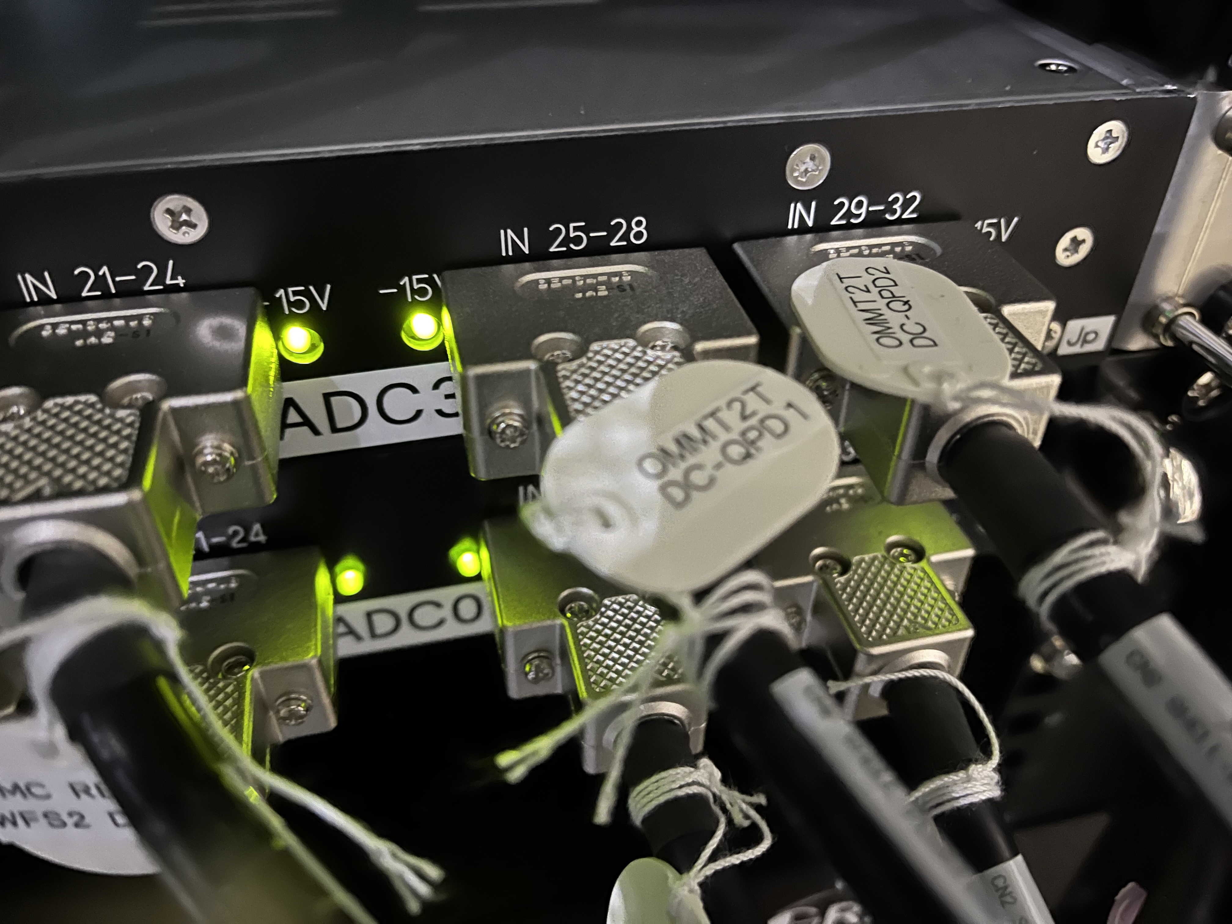
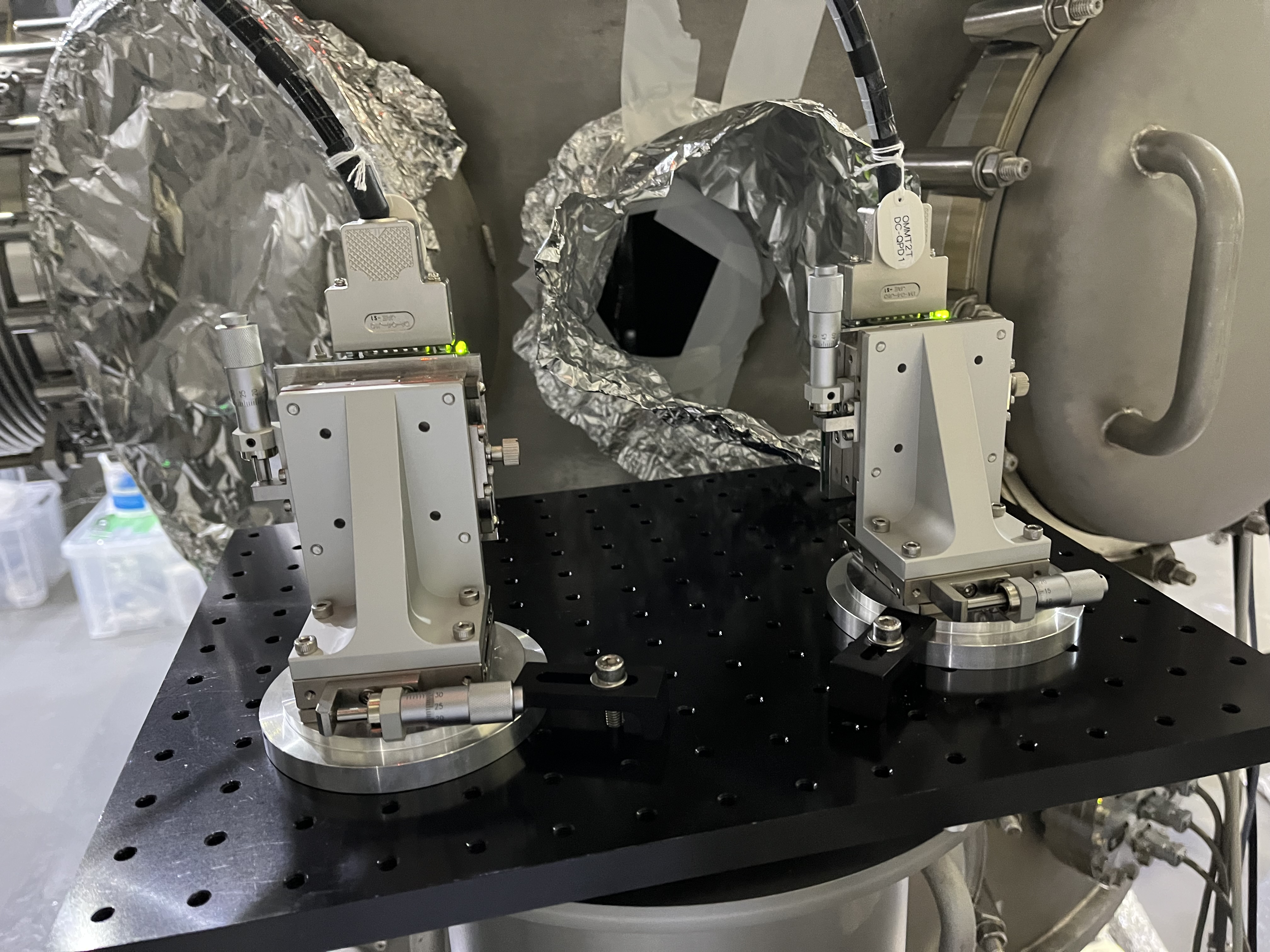
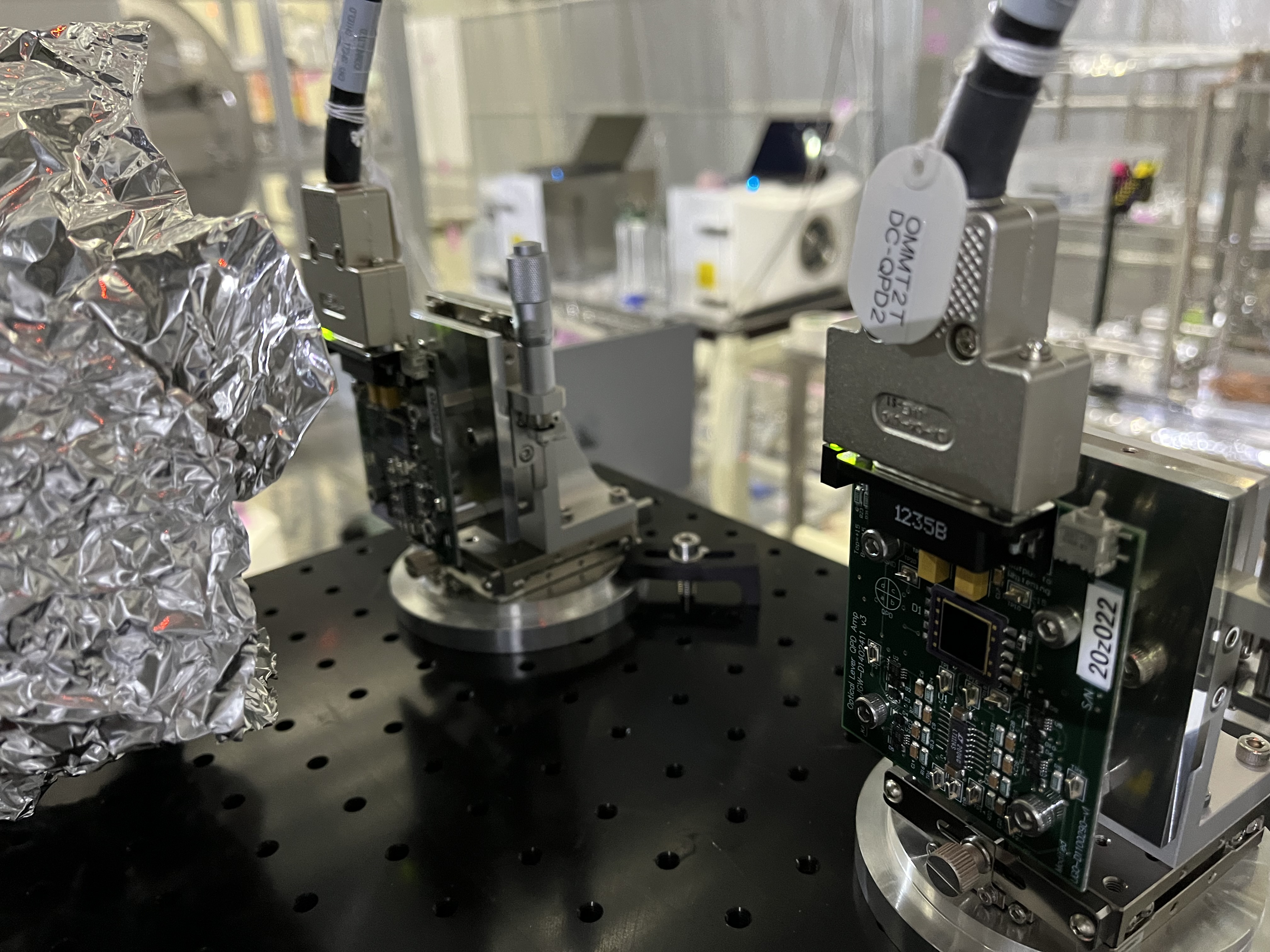
- Miyoki-san and the colleagues helped to lay two Dsub15 cables from the OMMT2T to the OMC0 rack. After installing relevant circuits (22844), we connected two QPDs to ADC3 channels; ch 24-27 to OMMT2T DCQPD1, and ch 28-31 to OMMT2T DCQPD2 (Fig.1). As usual, to connect the Dsub cables and the QPD circuits, nut-like parts were required and Yokozawa-san brough them for us.
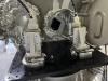
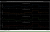
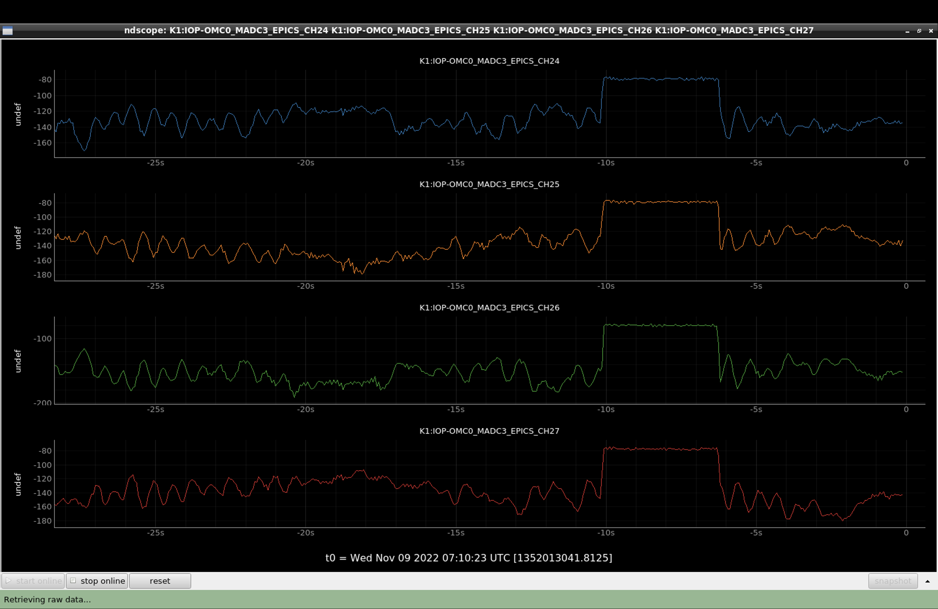
- Due to very faint IR power compared with ambient light on the QPD , the S/N was bad. So I made a tentative hut for the QPD1 and switched its gain to the higher (Fig. 2 and 3); not gain change for QPD2. Now when tuning off the room light, you maybe able to see around 120-140 counts maybe as the IR beam signal (Fig. 4), where in -10 sec to -6 sec I just shut the IR beam in-between OMMT1 and OMMT2. Because we did not prepare any RT models nor MEDM screens, I just checked these raw ADC signals as a first step. As shown in Fig. 4, I somehow did centering...
Some notices
- Need to install a viewport window
- The optical table for the OMMT2T optics might interfer against some clamps for a flange just under this optical table; maybe need to rotate slight later...
- I may put torque too much for the clamp to fix the QPD1 so the clamp seemed slightly bend. Sorry.
- Need a kind of cover to avod the amibient light effect as much as possible as the IR beam is quite faint.
