### Abstract
After the OSTM recovery by Takahashi-san (klog22836), I aligned the input axis about OMC QPDs with OMMT2 and OSTM and engaged the QPD centering loop. After that, I scanned the OMC cavity with PZT HV1 to find where the power of transmitted light was at its maximum. Finally, I locked OMC for around 10 seconds.
### What we did
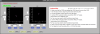
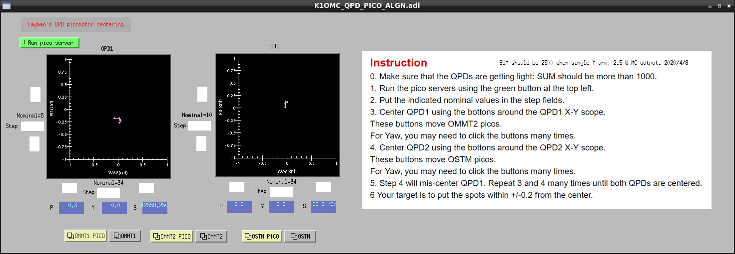
- I aligned the OMMT2 and OSTM with each pico-motor to center each beam spot on each QPD according to the instruction on the "Layman's pico" MEDM screen (fig.1).
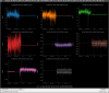
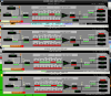
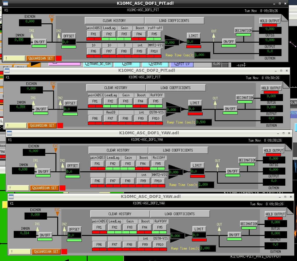
- I enganged the centering loops for each QPD. the centering loops worked well (Fig.2). Fig.3 shows the filters of each centering loop. (The boost filter is turned off in the photo but was turned on during control.)
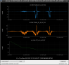
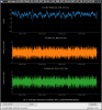
- I used PZT1 to scan the OMC cavity to find where the power of transmitted light was at its maximum. Since there was no camera at the transmitted light port this time, I determined that the TEM00 flash was where the amount of transmitted light was about the same as the previous value (klog22313), ~30mW. (Fig. 4)
- The curious thing is that the light intensity appears negative just before the maximum amount of transmitted light.
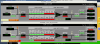
- After that, I locked OMC is locked. the lock is kept for 10 seconds. Fig. 5 shows the time series of the transmitted power(top), the error signal(middle), and the feedback signal(bottom). Fig. 6 shows the filters of the OMC length control. Like the previous lock, The feedback signal seems saturated because OMC is still in the air.
### Note
- After the OMC lock, Tamaki-kun, Yokozawa-san, and I confirmed FPMI could be locked.
- We need to check whether OMMT2 and OSTM don't touch their magnet on each IM tomorrow.