I modified Terrence's Jupyter notebooks for the calculation of the sensor correction filter using the H-infinity method.
Sensor correction refers to the subtraction of seismic noise (measured by a seismometer on ground) from the IP LVDT channels, and the sensor correction filter aims to remove low frequency noise from the seismometer before the subtraction takes place.
As shown in Terrence's thesis, this problem can be formulated mathematically in a similar way as the problem of the blending of two filters (Eq. 7.18), with the additional constraint that the corrected LVDT is affected by LVDT intrinsic noise. This implies that it's not necessary to remove the seismometer noise far below the LVDT noise, as we tend to do.
The process is divided in four steps, each one executed by a separate notebook:
- Fit a transfer function model to measured LVDT noise via an empirical model (Figs. 1, 2). The data shown in the figure was measured during high microseismic, but it's better to measure it when it's low, otherwise, fitting the empirical model may be very difficult.
- Fit a transfer function model to measured seismometer noise via an empirical model (Figs. 3, 4). The data is padded at low and high frequencies per H-infinity method requirements.
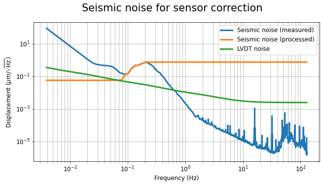
- Modify seismic noise at high and low frequencies, and fit a transfer function model to such data (Figs. 5, 6). The modifications are described below.
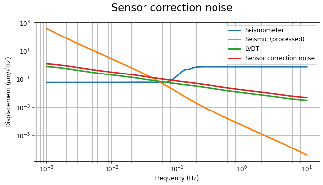
- Calculate the sensor correction filter and the sensor correction noise (Figs. 7, 8).
As shown in Fig. 5, at low frequencies, the seismic noise is artificially lowered below the LVDT noise, in order to allow the filtering of the seismometer noise to reach the LVDT noise level (per Eq. 7.18). At high frequencies, the seismic noise is set equal to the maximum of the microseismic peak, in order to take into account variations of the peak to higher frequencies when different oceanic weather conditions occur.
Figs. 7 and 8 show the sensor correction filter and the sensor correction noise defined by Eq. (7.18).
Currently, I'm using old SRM data just to test the procedure, but I aim to use more suitable data in the near future. The location and names of the files are:
- /kagra/Dropbox/Subsystems/VIS/vis_commissioning/sr2/notebook/sensor_correction/ and subdirectories.
- 1_lvdt_noise_tf_model.ipynb
- 2_seismometer_noise_tf_model.ipynb
- 3_seismic_noise_for_sensor_correction.ipynb
- 4_sensor_correction.ipynb
- Conda environment: vishack.


