Takase, Tanaka
### Abstract
We replaced the summing adaptor with a new one. Since the range of change of the correction gain by the adapter is small, we checked whether FPMI locks once without changing the correction gain, and it locked successfully. Therefore, we did not change the correction gain and left it at the current correction gain.
### What we did
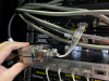
- We has replaced the summing adaptor with a new one (fig.1). The difference between the old one and the new one is that the old one was to mix the 24 kHz signal created by the function generator with the control signal of the ETMX, while the new one is to mix the 24 kHz signal created by the DGS 64 kHz model with the control signal.
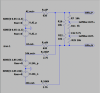
- As DACs for the model, we used ch9-12 of DAC1 in the EXV1 rack. (fig. 2)
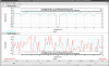
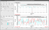
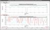
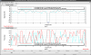
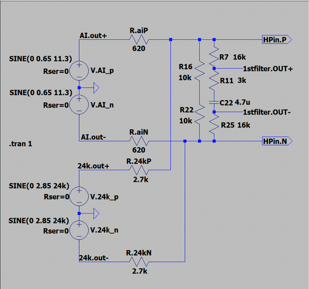
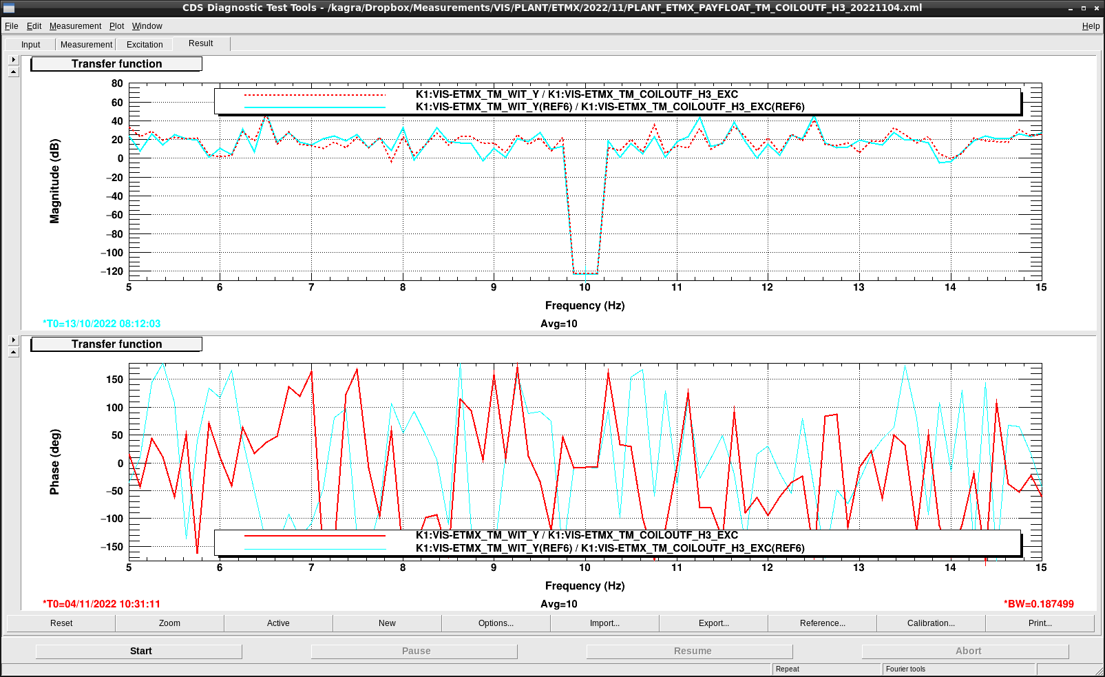
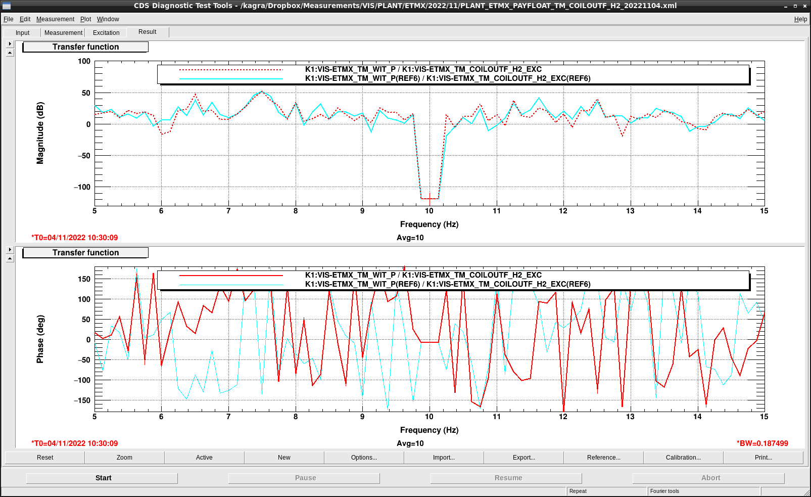
- As before, the transfer function from the output from the DGS to the coil to the Oplev signal was measured at 10 Hz to compensate for the voltage drop in the control signal due to the summing adapter. Figure 3 shows the circuit diagram of the newly introduced summing adapter. The old summing adapter had a correction gain of 2.7 dB = 1.36 times, but the new one is designed to have a correction gain of only 1.3 times. In other words, the change from the previous correction is expected to be about 1.36/1.3 = 0.4 dB. Figure 4-7 shows the transfer function results for each coil. The cyan line is the transfer function with the previous adapter in place and the red dotted line is the transfer function with the new adapter. As a result, we confirmed that the change in all coils is within about 0.4 dB.
- Since the range of change was small, we checked whether FPMI would lock once without changing the correction gain, and it locked successfully. Therefore, we did not change the correction gain and left it at the current correction gain.
### Note
At first, according to the DAC channel assignment list, ch1-4 of DAC1 of EXV1 was available, so I planned to use that channel, but when I actually went to the site, I found a cable labeled "IM DAMP" was connected to the lowpower coil driver, so I hurriedly used a different channel.
