Currently, the ADC is saturating in the OMC DCPD signal acquisition. The transimpedance gain is set to 400 Ohm but we would like to reduce to 100. We also want to implement automatic switching of the respective gain filters in medm.
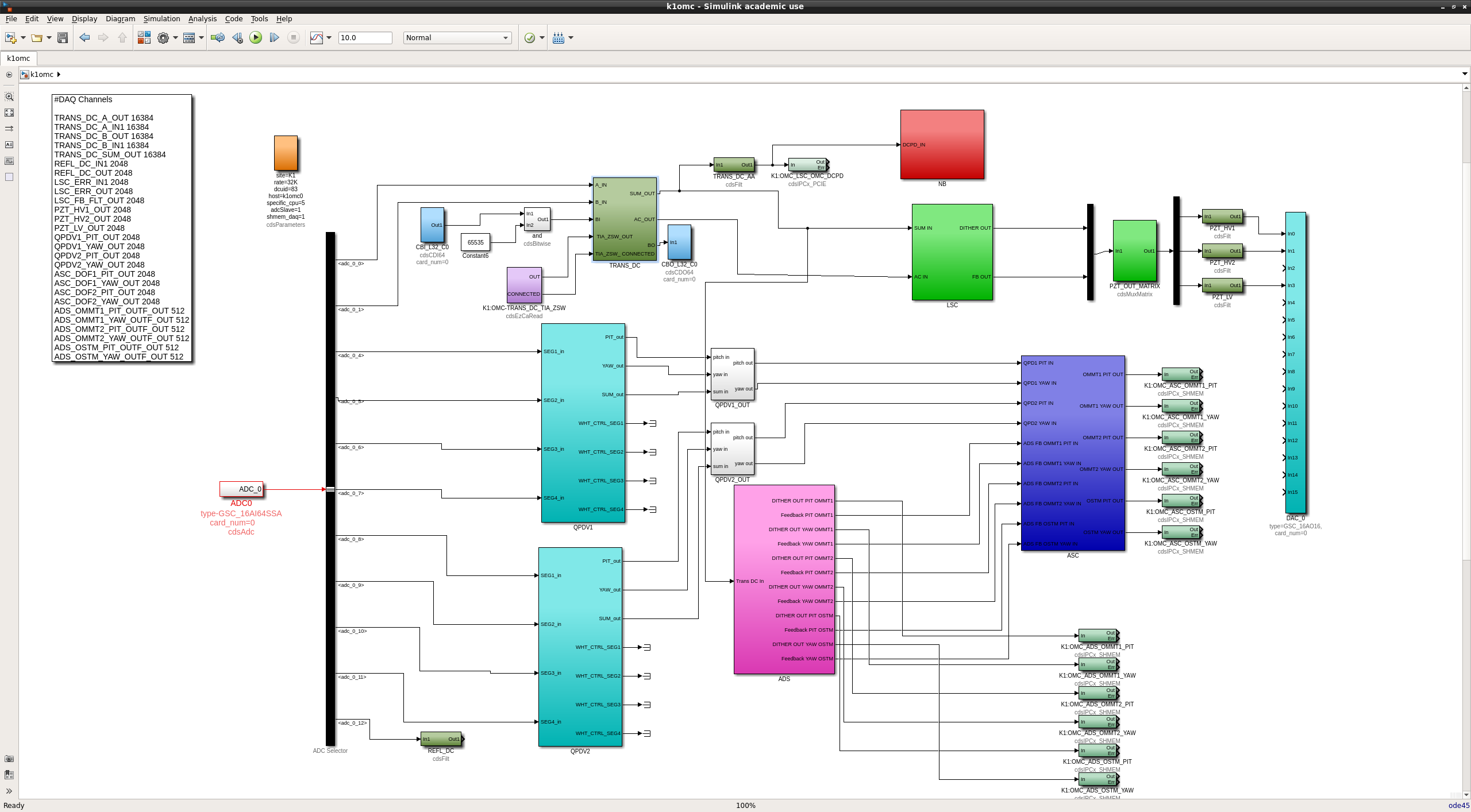
We made a modification to the RCG Simulink model of k1:OMC by adding a cdsEzCaRead block to the top level of k1omc.mdl (figure 1). The outputs are:
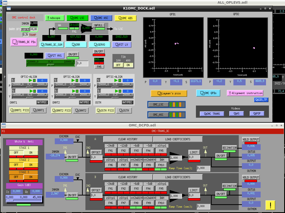
OUT: 1 if transimpedance gain is 400, 0 if transimpedance gain is 100. Checked by adjusting the TIA switch in the OMC dock (settings are only 100 or 400, see figure 2) and then checking ezcaread K1:OMC-TRANS_DC_TIA_ZSW in a terminal.
CONNECTED: 1 if the channel is connected, 0 otherwise.
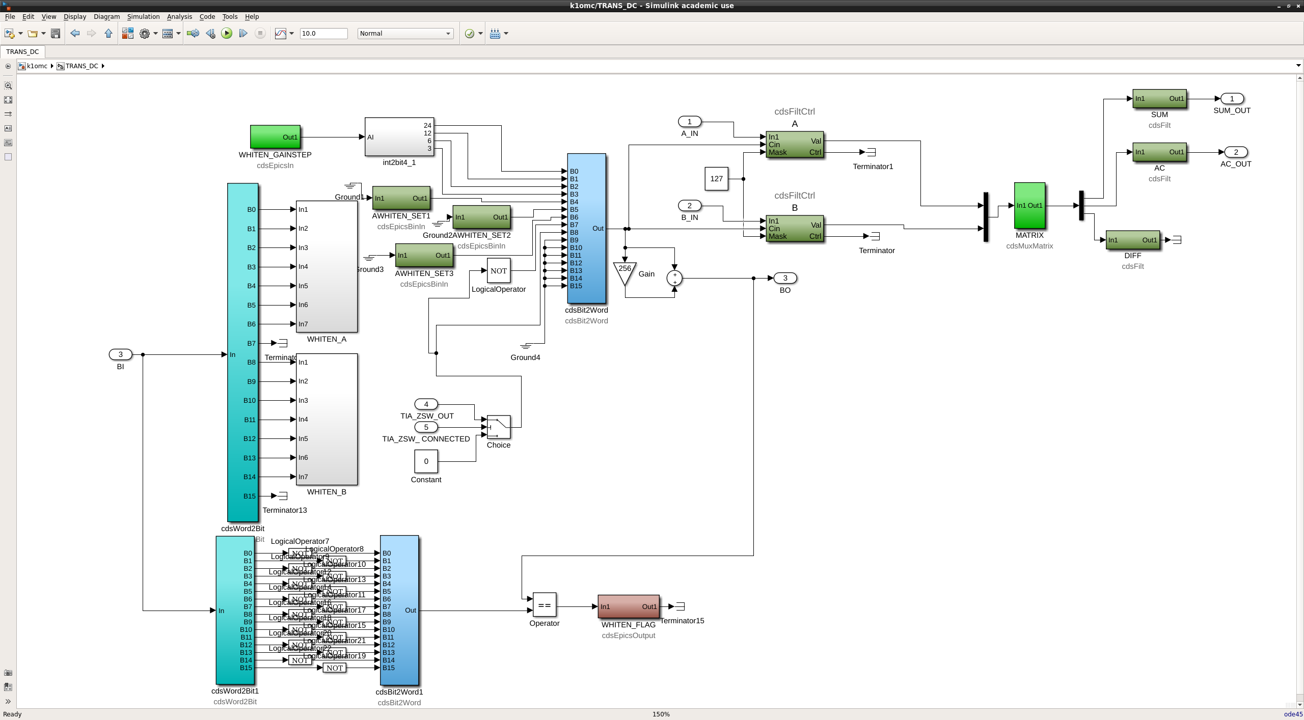
These outputs are then sent inside the TRANS_DC block (figure 3). There, we added a switch which outputs the state of TIA if the channel is connected, or 0 if not. The switch output is sent to the cdsBitToWord block, B7 for 100 Ohm and B8 for 400 Ohm, such that only one is activated at a time. Respectively, B7 and B8 are linked to the counts-to-mV filters 8 and 9 in OMC_DCPD filter banks (figure 2). If the channel is not connected, the transimpedance gain will be set to 100 Ohm.
A button with a popup detailing the automatic filter switch was implemented in the OMC dock.
We compiled k1omc and are waiting to reboot the digital system to update.

Ikeda, Michael
I checked to confirm the appropriate behaviour of the OMC_DCPD filter banks. When TIA is set to 100, FM8 should be on and FM9 should be off, and vice versa for TIA set to 400 (see figure 2). However, there was no change in the filter banks when I changed the TIA setting.
I tried replacing the switch in figure 3 with an AND gate (TIA_ZSW_OUT AND CONNECTED) but it didn't make a difference. Then I just removed the AND gate, sent CONNECTED to a terminator and put TIA_ZSW_OUT into B7 and B8, with the NOT gate still before B7. But that didn't make any difference either.
When I change the TIA setting in the OMC dock I can clearly see a change in the output signal of the DCPD, and using caget I can confirm that TIA_ZSW_OUT is going between "ON" and "OFF" (or 1 and 0 if using ezca read). So I guess the problem is somewhere between the model and the interface.