Reports 1-1 of 1 Clear search Modify search
MIF (General)
masahide.tamaki - 22:43 Monday 12 September 2022 (22073) Print this report
MICH and FPMI Lock

[Ushiba, YamaT, Tamaki]

Summary

We calculated some calibration factor and wrote the guardian for MICH and FPMI lock.
In the end, both MICH and FPMI are locked.

Detail

MICH

After alignment work, we set to work on the MICH Lock.

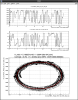
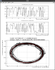
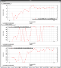
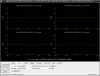
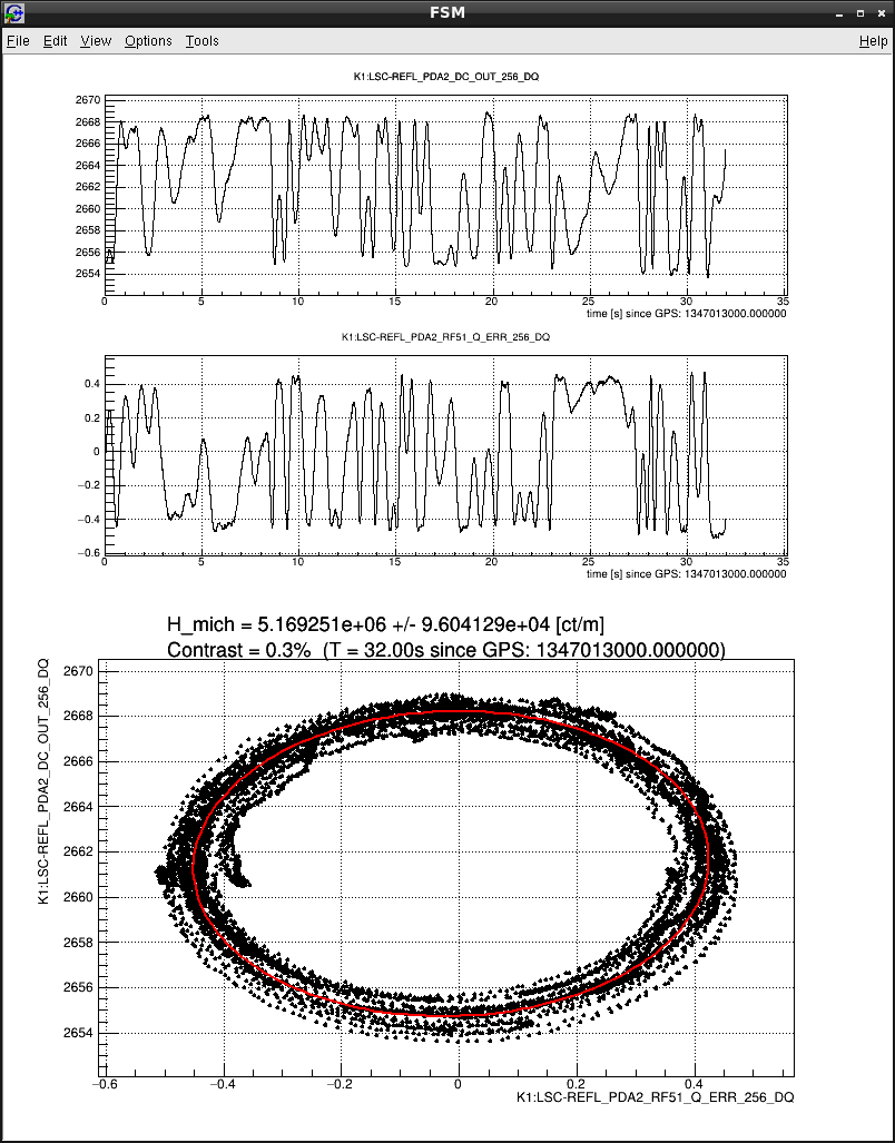
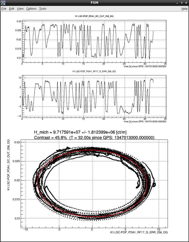
At first, we obtained counts per meter for each of RF17 and 51 by Ellipse Fitting to determine the calibration factor (Fig1,2).
* Ellipse Fitting draws an ellipse from the RF and DC channel signals to obtain the number of counts per 1 m.

Then it was converted to m/cnt using the following calculation and put in the filter bank (MICHcal).

► Calculation of calibration factor
   RF51: 1 / 5.17e6 * 2.378 〜 4.84e-7
  RF17: 1 / 9.72e7 * 2.378 〜 2.59e-8

    * 2.378 is power scale
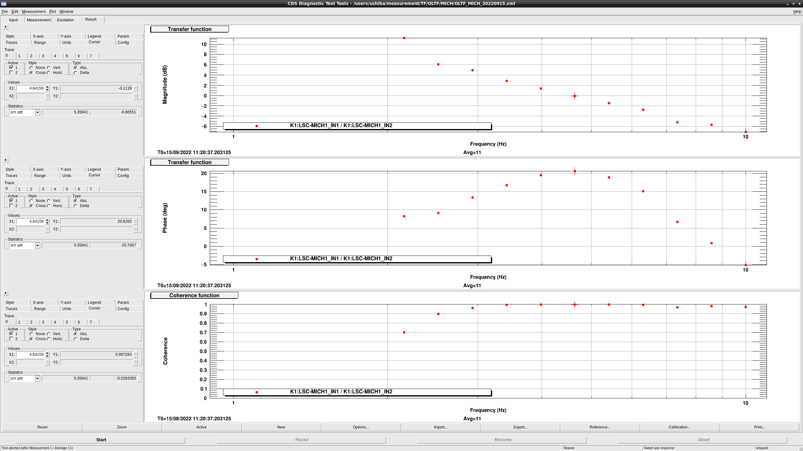
► The gain was adjusted with the FB of LSC_MICH.

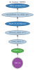
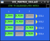
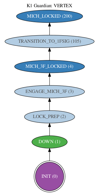
Next, we add 'TRANSITION_TO_1FSIG' state to the VERTEX GRD to switch 1F signal from 3F (Fig3).
In this state, the velue of INMTRX['MICH','REFL51Q'] and  INMTRX['MICH','POPA17Q'] are exchanged (the former goes from 1 to 0 and vice versa, so this means switching from 3F to 1F).

And we also added a state 'MICH_LOCKED' to lock MICH at 1F (Fig3).

Finally, we made sure that guardian worked well and that MICH was locked.
(An instruction to restore the value of INMTRX when lock was down also been added to 'DOWN' state.)

FPMI

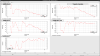
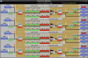
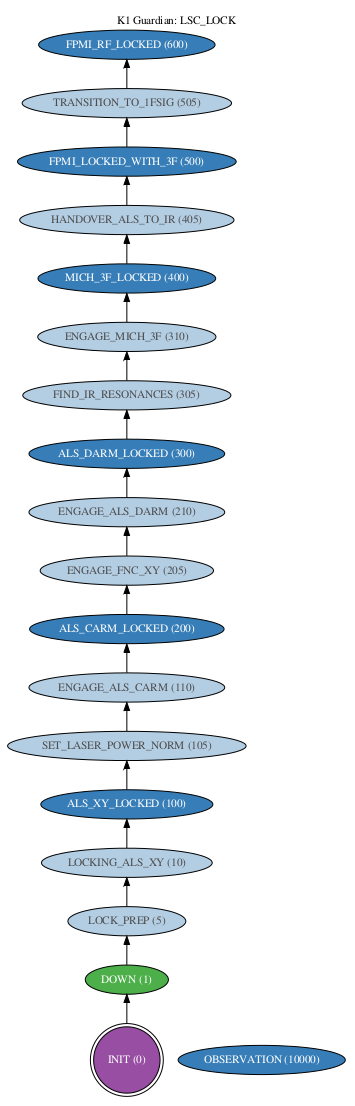
To lock FPMI at 1F, we add the 'TRANSITION_TO_1FSIG' state to LSC_LOCK GRD (Fig4).
This state makes VERTEX GRD request 'MICH_LOCKED' state.

Then, we add the 'FPMI_RF_LOCKED' state, and we have confirmed that FPMI can be locked by LSC_LOCK GRD.

Images attached to this report
Comments to this report:
tomotada.akutsu - 23:10 Monday 12 September 2022 (22076) Print this report

Great!

takahiro.yamamoto - 15:50 Tuesday 13 September 2022 (22085) Print this report

K1:CAL-CS_PROC_DARM_DISPLACEMENT_DQ is now available.
Note: current calibration assume actuator efficiency is not so change from post O3GK commissioning. When I have time, I'll measure it.

I haven't checked dynamic range of current spectrum.
If whitening filter is required to suppress numerical error, I will prepare it in the next DARM lock.

-----
FPMI can be locked enough stable to measure the open loop transfer function of DARM.
Fig.1 shows the DARM OLTF and the TF from DARM2_OUT to DARM1_IN1.
UGF lies around 50Hz which is designed value by DARM servo filters.

Fig.2 shows the optical gain between DARM displacement and DARM1_IN1 which is estimated by compensating known gain and filters from TF from DARM2_OUT to DARM1_IN1.
As a result, optical gain between DARM displacement and DARM1_IN1 is -2.0.
Compensated component is as follows.
- Actuator efficiency (from SUMOUT_OUT to DARM displacement) in O3GK: -4.6e-12 [m/ct] (See JGW wiki)
- EUL2OSEM factors (four times smaller than ones in O3GK): 0.25 (See Fig.3 and Fig.4)
- COILOUTF_GAINs (twice larger than ones in O3GK): 2.0 (See Fig.5 and Fig.6)
- Filters in TM_LOCK_L: -6dB (above 20Hz).
- Pendulum response: f^-2
- Cavity pole: p18Hz

Images attached to this comment
takahiro.yamamoto - 15:33 Wednesday 14 September 2022 (22097) Print this report

Something like a sensitivity.

Sum of red and blue curves in Fig.1 is roughly estimated sensitivity in-air FPMI with AS17.
Now only TM is taken into account, so the sensitivity below 30Hz is not so accurately due to the effect of IM (and MN).

Brown curve represents a dark noise at AS PD measured today.
ADC noise should be ~1e-17m/rHz @10Hz which is lower than the measured noise on AS PD channel, because two z1;p10 whitening filter are now enabled.
1e-17m/rHz = 1e-6[V/rHz] / 610[uV/ct] * -234dB(AS17Q filter bank) / 2.6(laser power norm) * -0.8(lsc input matrix) / 100(whitening gain above 10Hz)

Black curve shows a FPMI sensitivity when we achieved 1.3kpc during O3 commissioning reported as klog#10869.

Images attached to this comment
takahiro.yamamoto - 17:36 Wednesday 14 September 2022 (22098) Print this report
Now MICH control signal has large coherence with DARM error signal in wide frequency region as shown in Fig.1
According to klog#21664, current UGF of MICH loop is around 22Hz.
On the other hand, it's around 7Hz in O3GK. So it may be better to move MICH UGF to lower frequency.
(And also, Ushiba-kun said roll-off filter hasn't been implemented yet for MICH loop.)
Images attached to this comment
takafumi.ushiba - 12:46 Thursday 15 September 2022 (22114) Print this report

Yesterday, I reduced the MICH UGF from 22 Hz to 5 Hz (design).
Due to the large earthquake, I cannot measure the OLTF of MICH loop after the modification, so we need to do it at some point.

takahiro.yamamoto - 14:37 Thursday 15 September 2022 (22118) Print this report
MICH calibration was updated because MICH gain at LSC-REFL_PDA2_RF51_{I,Q} and LSC-POP_PDA2_RF17_{I,Q} had been changed as 4.84e-7 and 2.59e-8, respectively.
By this update, K1CAL-CS_PROC_MICH_DISPLACEMENT_DQ can be available as the calibrated MICH displacement.

diaggui template of sensitivity monitor of MICH and DARM are saved as
- /users/Commissioning/templates/diaggui/MICH/CAL_MICH_DISP.xml
- /users/Commissioning/templates/diaggui/DARM/CAL_DARM_DISP.xml
masayuki.nakano - 14:39 Thursday 15 September 2022 (22119) Print this report

I can't wait pumping!!

takafumi.ushiba - 10:55 Friday 16 September 2022 (22132) Print this report

I measured MICH UGF and seems around 4.6 Hz (fig1).

Images attached to this comment
Search Help
×

Warning

×