[Yuta Michimura, Takafumi Ushiba, Masahide Tamaki, Haoyu Wang]
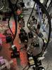
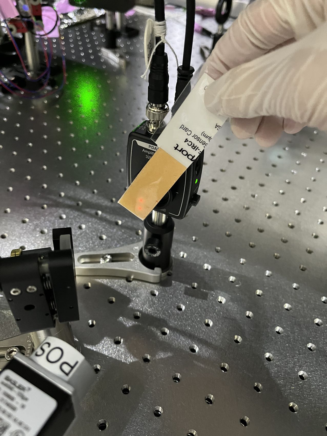
During Sep 1 evening, we installed both PDs and cameras for POP. The current installed optics can be found here POP. Please also see Fig 1 for the photo.
* RLNS2 (f=-100mm) is installed to get a reasonable beam size on PDs and cameras. The outgoing beam now has a much smaller divegent angle. The PD (PDA100A2) actually has a quite large sensor (75.4mm^2), larger than the CCD.
* The HWP (before the TFP) is removed. We checked the amount of p-pol power didn't change after we remove the HWP. This means the effect of steering mirrors on polarization rotation at POP is small. These steering mirrors include 1) the steering mirror after PR2 in tank, 2) the periscope, 3) HBS1, 4) RST1 and RST2.
* RBS1 and RBS2 are replaced by non-polarizing beam splitter from Sigma-Koki (NPPH(+/-5%)Q-25.4C06-20-W0.5D-1064) designed for both s-pol and p-pol. The beam size at RBS1 is a bit large. We found the beam can be easily clipped for 45 degrees incidence. We should replace it with a 2-inch mirror next time if we keep the current design.
After the POP optics installation and alignment, we measured the beam power and shape at POP, and also the beam power at POS.
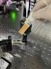
Then, we also checked the beam alignment to the two PDs at POS. We found there were two beams around the PD sensor, see Fig 2. We identified that one beam came from the aligned ITM. The other beam came from the misligned ITM from another arm. When the misalignment is small, the PD probably can see this beam. We put a iris before PBS to dump the unwanted beam. All the beam powers were measured again at POP and POS. The gain of all 4 PDs is set to 40dB.
Figures:
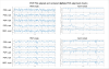
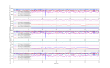
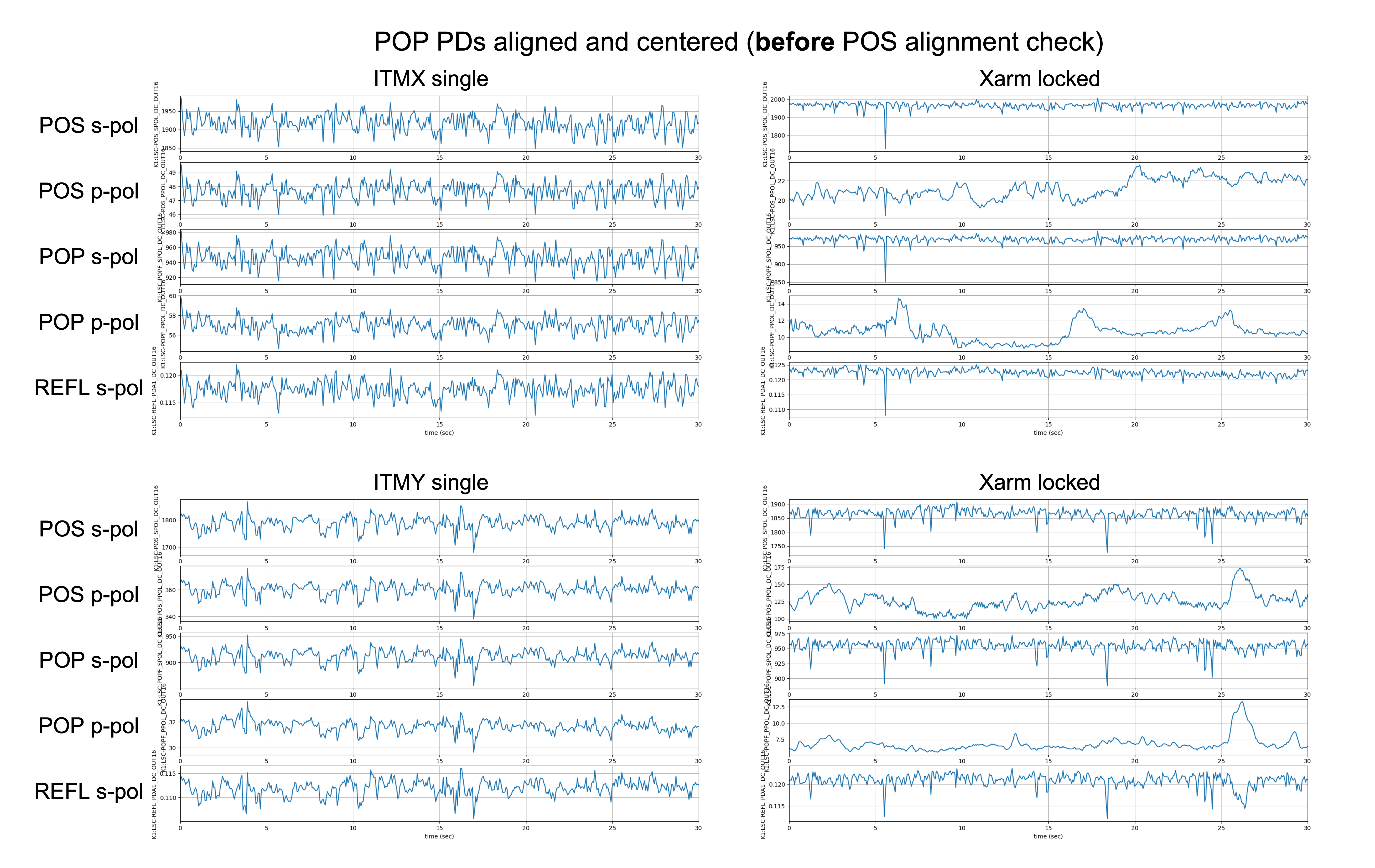
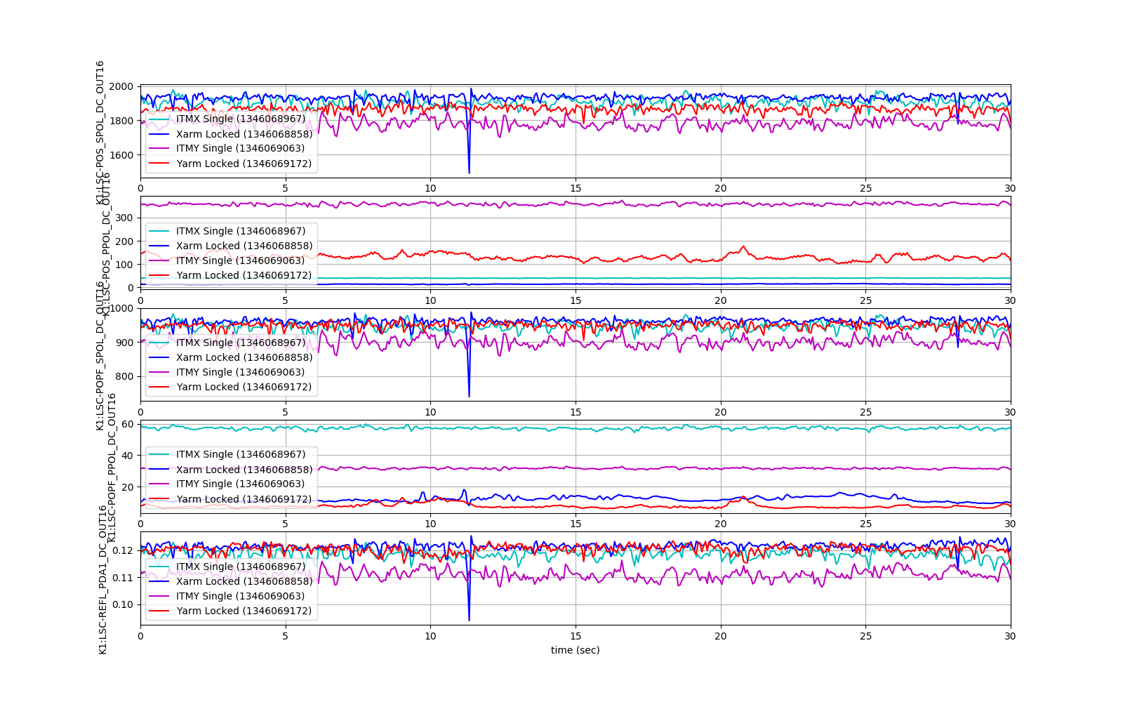
Fig 3: Power measurements at POP and POS. For these measurements, we installed PDs and cameras at POP, but we didn't check alignments to PDs at POS yet. The REFL s-pol power is also plotted as a reference. All the 5 PDs show same power fluctuation for single bounce case. When the cavity is locked, the s-pol power from POP and POS matches with each other. But the p-pol power fluctuations at POP and POS are different.
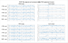
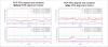
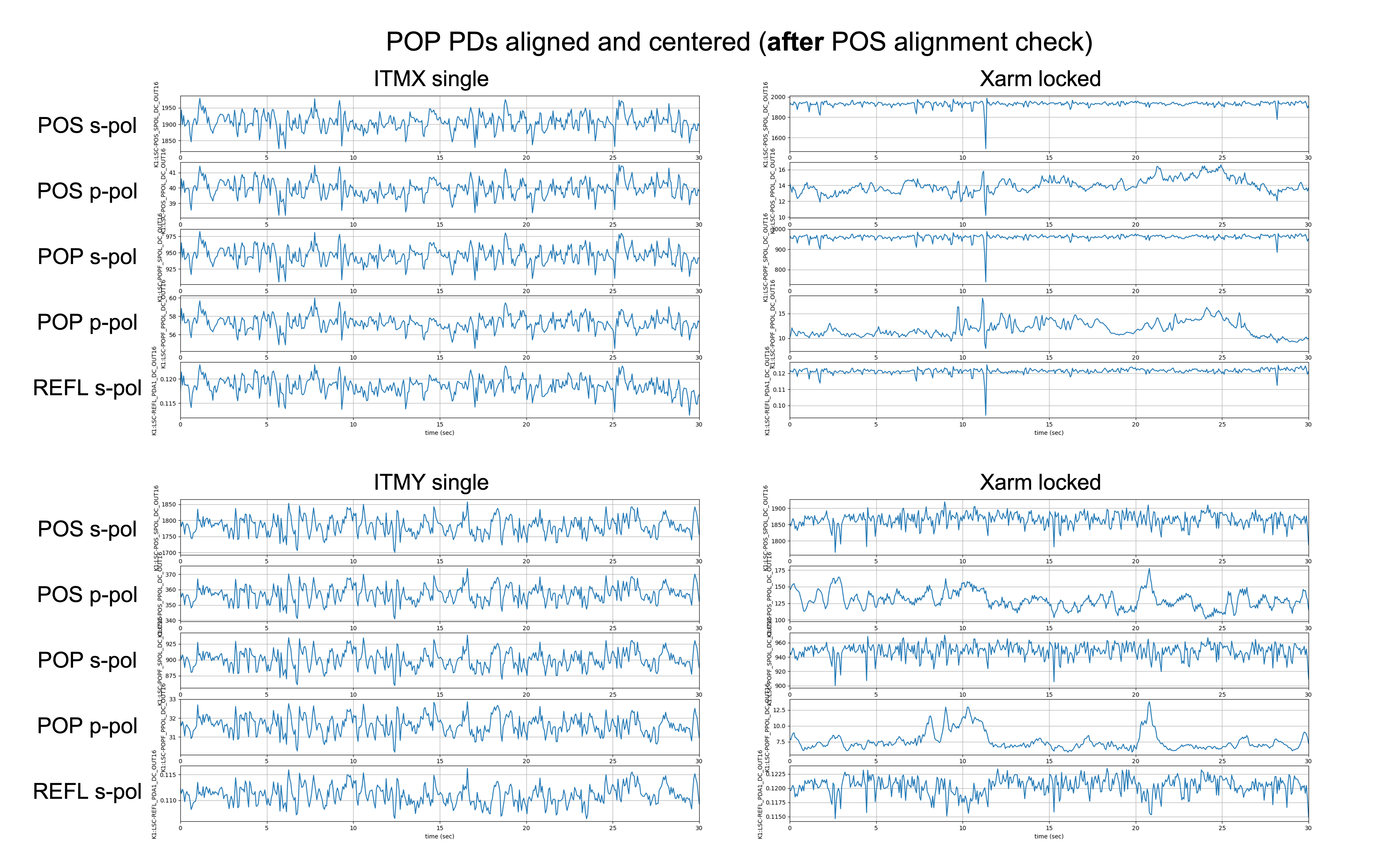
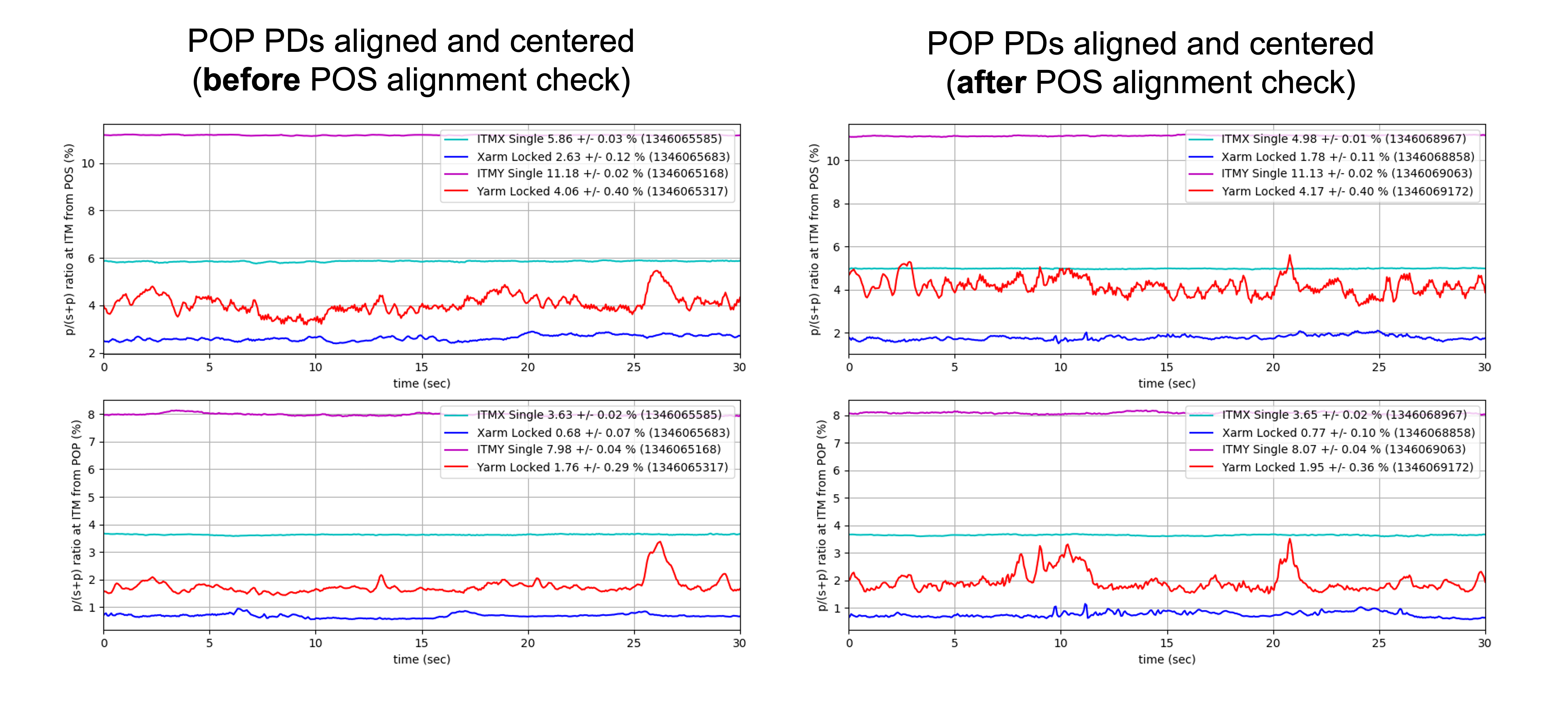
Fig 4 and Fig 5: Power measurements after we check and align the beam at POS. The two figures use the same data but with different subplot plotting styles. The p-pol power fluctuations at POP and POS match better but there is still slight difference.
Fig 6: The calibrated p-pol power percent. The power from Xarm reduces after we dump the unwanted beam at POS.
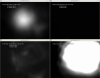
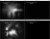
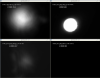
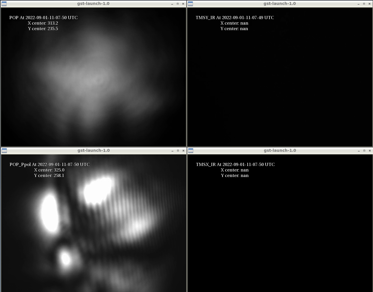
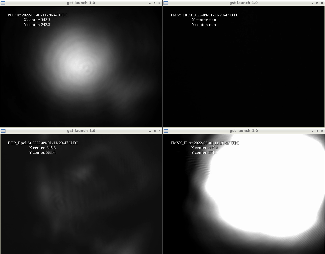
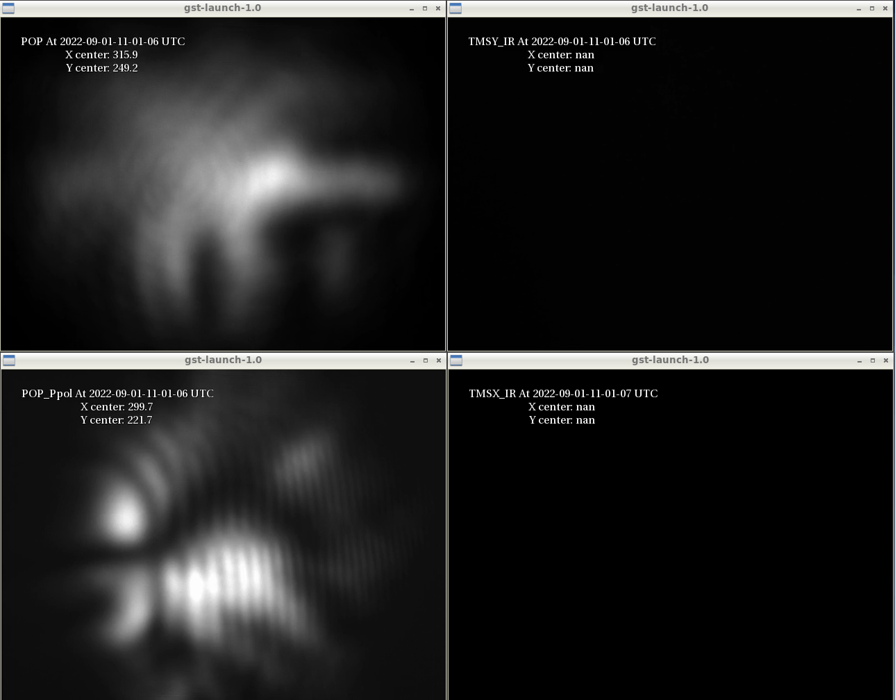
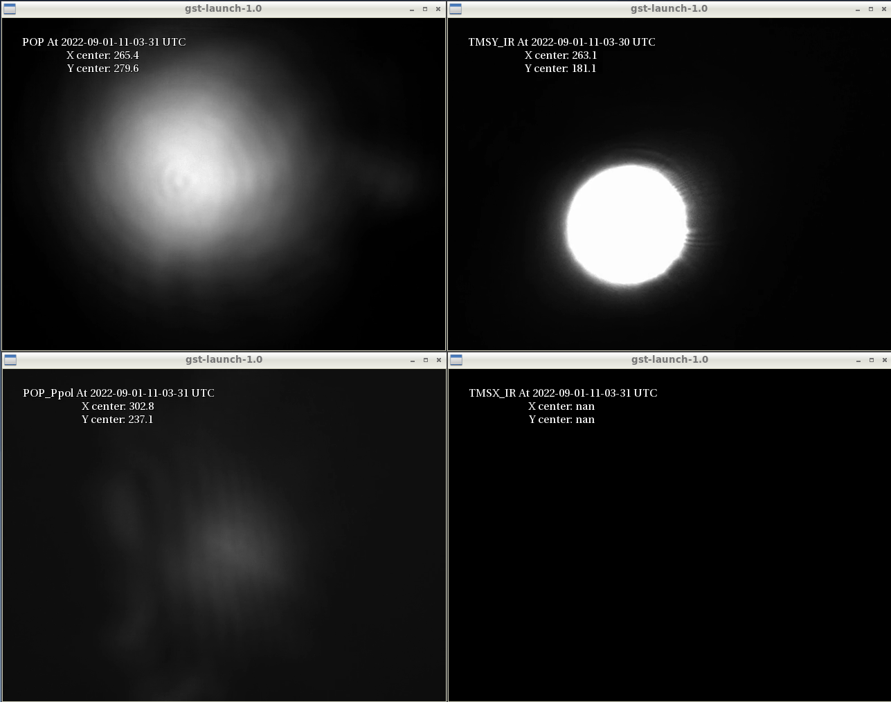
Fig 7 ~ Fig 10: Cameara images of beam shapes for ITMX single bounce, Xarm locked, ITMY single bounce and Yarm locked, respectively.
The two videos show the beam shape when arm cavities are locked. During the lock, the beam seems moving quite a lot for Yarm. When s-pol beam is stable at the center, we can see the p-pol is almost round. This matches with our assumption of mode healing effect. When s-pol is off-centered, the p-pol beam changed to some higher order modes.
