Nishino, Miyazaki, Aso
It's been known that the OMC QPDs are noisy and glitchy.
We knew that the first stage op-amp oscillates when a cable is connected.
This is probably because of the capacitance of the cable.
In fact, as reported below, the QPD cables have large capacitance.
https://klog.icrr.u-tokyo.ac.jp/osl/?r=21829
The circuit diagram of the QPD driver is here:
https://dcc.ligo.org/LIGO-D1001974/public
In order to cancel the large input capacitance from the cables, we asked the AEL people to add large capacitors (100nF) in parallel with the feedback resistance (R4) of the transimpedance amplifier (U4 and U2).
We have installed this modified circuit to the CH1 of the QPD driver chassis, while CH2 has C3=150pF.
Noise comparison
We checked the waveform of the signals at TP3 (right after the transimpedance amplifier) and TP2 (right after the output buffer amp). There is a whitening filter (zero@0.39Hz, poles@39.8Hz and 79.6kHz) in between.
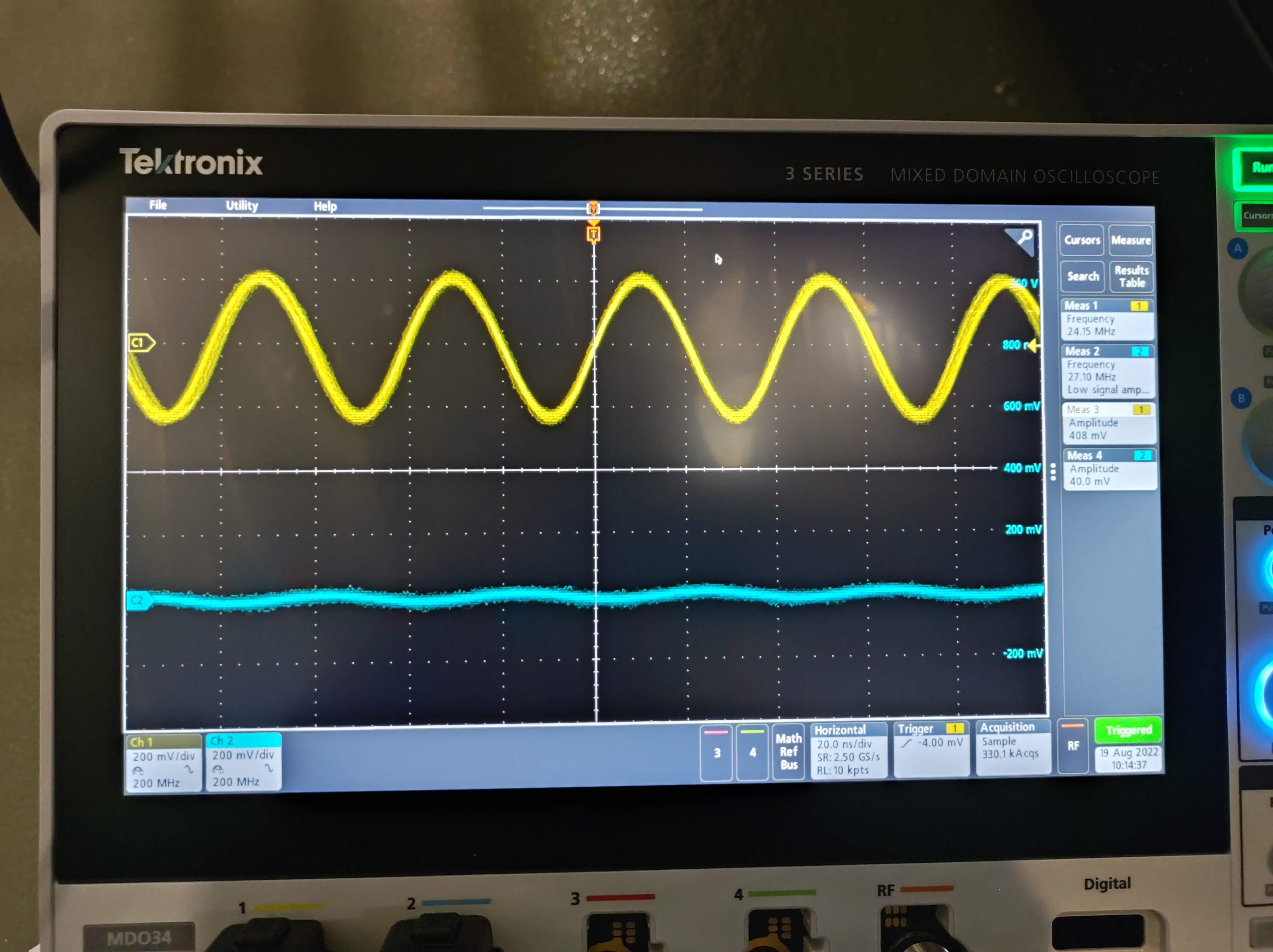
Below is the waveforms at TP3 with the QPD cables connected.
Oscillations at around 25MHz exist. The amplitude of oscillation is 10 times larger for CH1.
So, it looks the modification did more harm than good so far.
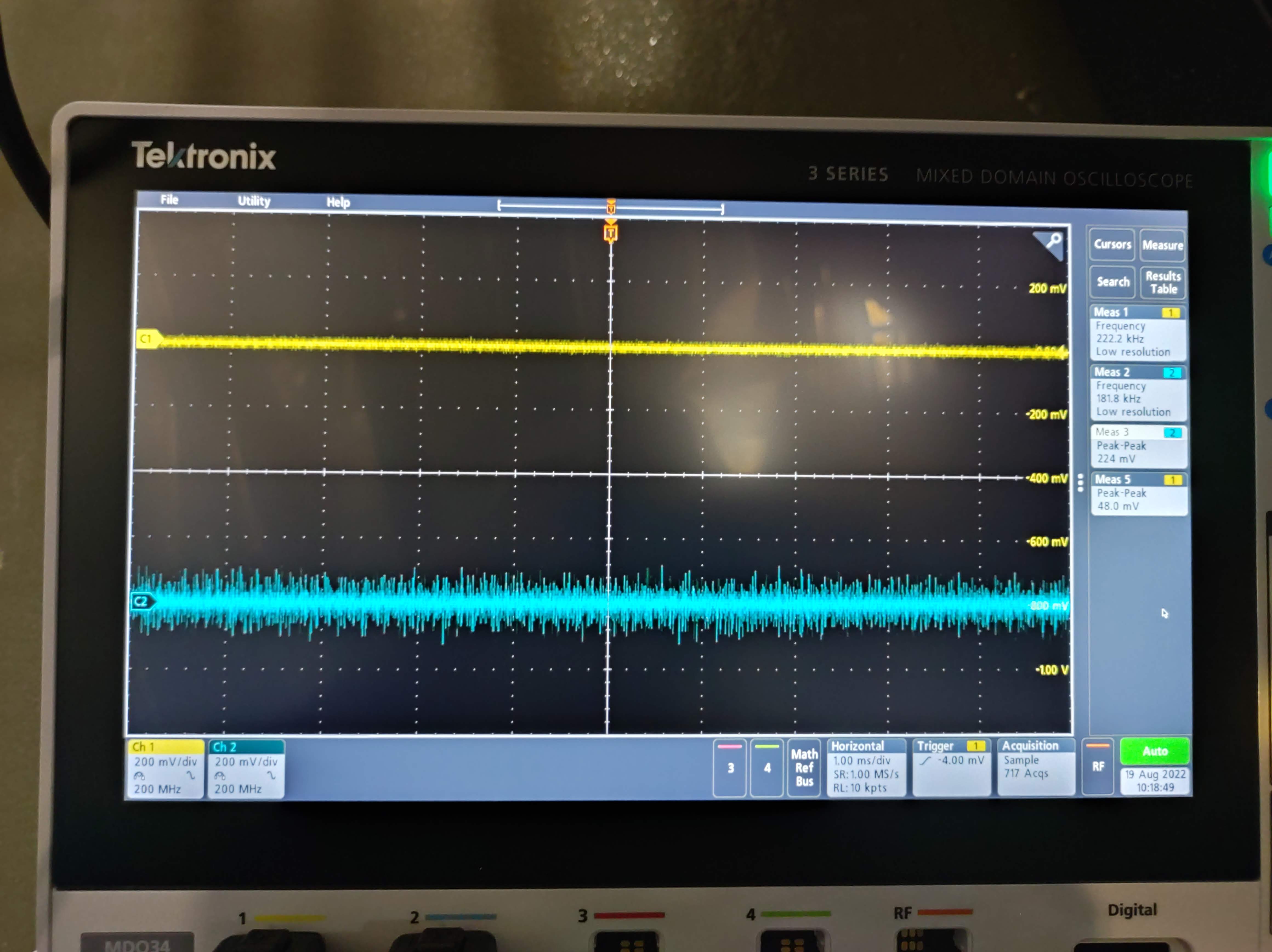
Below is the waveforms at TP2.
Here, the high frequency oscillation was filtered out. The low frequency noise is five times larger for CH2.
Discussion
While the oscillation at the initial stage seems bad, the final noise level is clearly better for C3=100nF. Since we only care about the low frequency signals in this application, it may be better to use the modified version for all the channels.
One thing worth trying may be to increase the input resistance (R8) from 10Ohm to a larger value, which may stabilize the high frequency behavior.


