Reports 1-1 of 1 Clear search Modify search
MIF (ASC)
hirotaka.yuzurihara - 23:05 Friday 19 August 2022 (21839) Print this report
Automatic identification of IR beam center is now available

[Kenta, Shiota (Aogaku), S. J. Tanaka (Aogaku), Toriyama (Aogaku), Yuzurihara]

This is a continuous work of klog#21742.

Whet we did

  • When we take the TCam photo, the IR beam center will be identified by the tool automatically. This is similar to the case of finding the mirror center by Green laser.
  • This script will launch only when the IR is locked (normalized power is larger than the threshold). The status of Pcal and Green laser is not related to the launch. 
    • For detail, see the shell script `~/bin/run_fit_Tcam_py.sh:calcenter`.
  • We implmented the developed tool on calcenter server. The python code is `~/bin/fit_IR_center.py:calcenter`, which was written by Aogaku members in the previous stay.
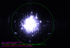
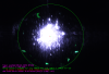
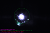
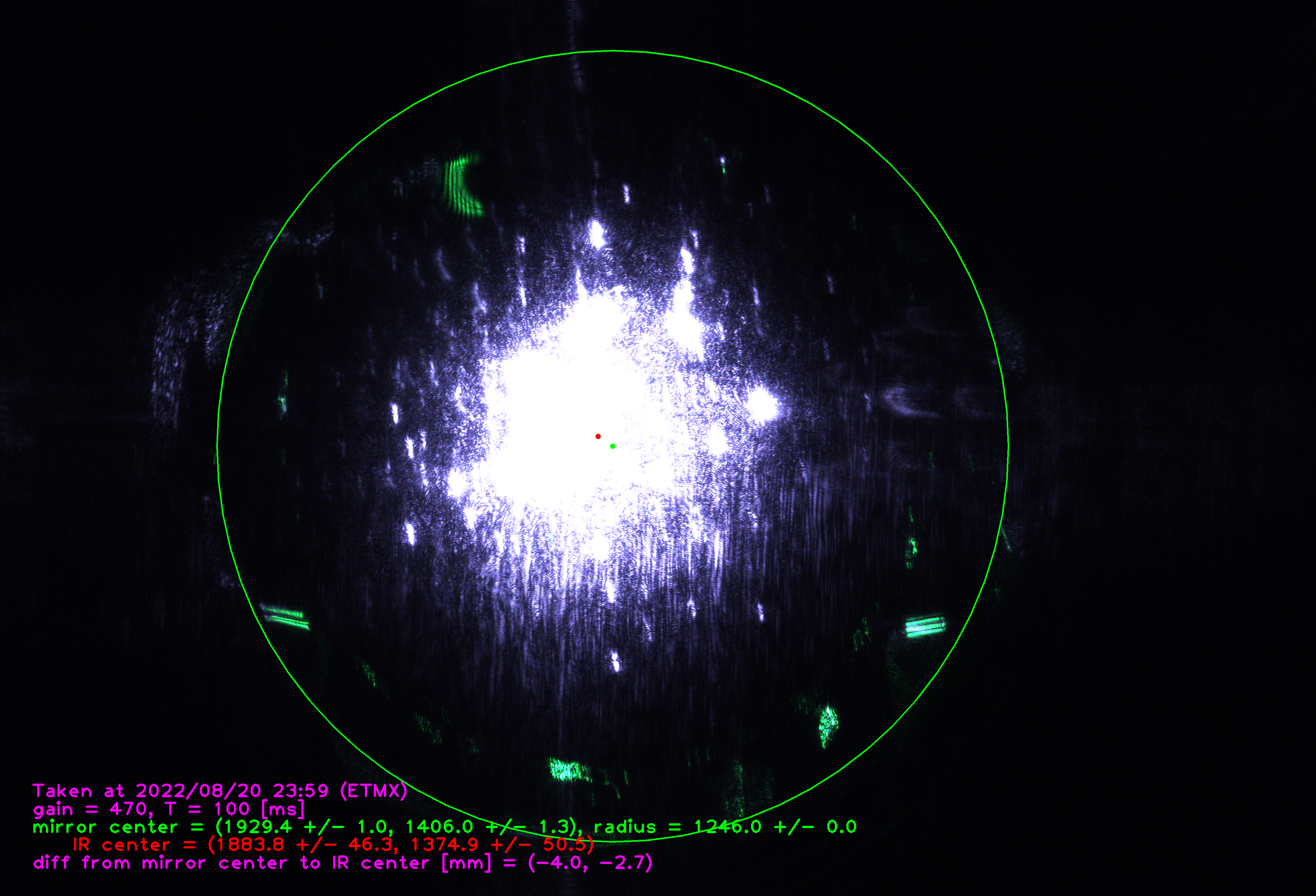
  • I attach one example of result.
    • In this example, the lime green circle shows the latest mirror edge.
    • The lime green dot shows the latest mirror center. These were estimated by Green laser in advance.
    • The red dot shows the IR beam center. Note that the color and design of text will be matured gradually. (Actually no time to spend on that...)
  • When you found the error or trouble, please let us know.

Remained tasks

  • Can we apply this tool to Green laser on ETMX?
  • Can we apply this tool to ETMY? I heard that IR laser on ETMY has the stain. It might block the identification of IR center. 
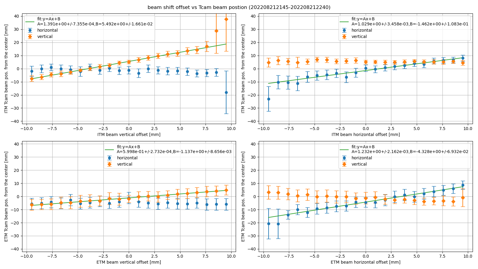
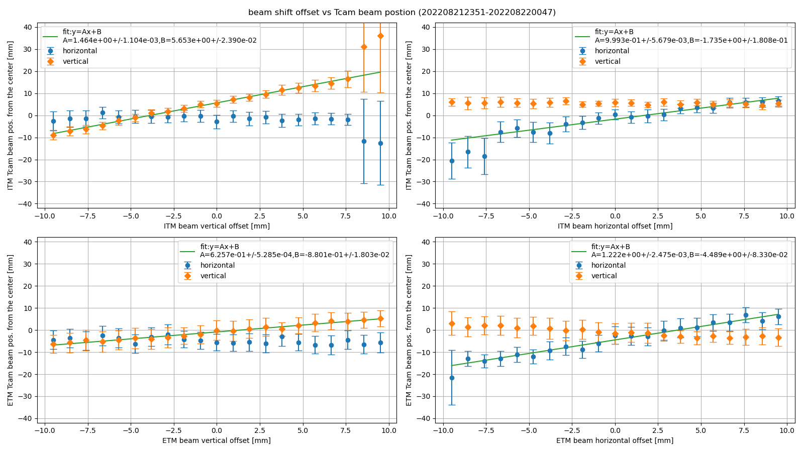
  • Check whether the IR beam position is correct or not (by Kenta's help)
  • Check whether the accuracy is enough or not
  • Update the appearance of result photo, such as color and text
Images attached to this report
Comments to this report:
hirotaka.yuzurihara - 21:59 Monday 22 August 2022 (21847) Print this report

I updated the code to use the mm unit for the difference between IR center and mirror center. See the attached screenshot.

Images attached to this comment
kenta.tanaka - 18:28 Thursday 25 August 2022 (21900) Print this report

Yuzurihara, Kenta

Thanks, AGU members for developing such a nice tool.

### Abstract

  • We checked the consistency between the amount of beam spot shift and the detected beam position by Tcam.
  • The detected beam position of ITM is almost consistent with the amount of shift within the error.
  • The ones of ETM has a little different from the amount of shift yet.
  • We need to sophisticate the algorism of beam position detection by Tcam to improve the accuracy of the beam position. 

### What we did

  • We measured each IR beam position of each TM of X-arm cavity with T-cam. We swept each beam position on each TM by shifting the cavity axis in the vertical and horizontal directions. and took some photos at each beam position.
  • We obtained each beam position from each photo by the tool developed by Yuzurihara-san and AGU members.
  • Figure1 is the results. The left side of the figure is the relation between the amount of the shift and the beam position derived by Tcam's photo when we shift the beam position in the vertical direction. The right side is the one when we shifted in the horizontal direction. The upper side is the beam position of ITM. The lower is the one of ETM. The orange points in each plot are the beam position in the vertical direction, the blue is the one in the horizontal direction. Each errorbar shows the error of the beam position by the tool. 
  • As you can see, The orange points on the left side of the figure move as we shifted the beam positions in the vertical direction. On the other hand, the blue points on the left side don't move so much. Similarly, the blue points on the right side of the figure move as we shifted the beam position in the horizontal direction. Now the beam position obtained by Tcam might be equal to the amount of the beam position shift, so these points should be on the line whose incline is 1. We fitted these points about y=ax+b with the weight of each error. The green line in each plot is the fitting results. According to the fitting results, the ratios between the amount of the shift and Tcam's beam position of ITM in both directions are about 1. The ratio of ETM in the horizontal direction is about 1.2. However, The ratio of ETM in the vertical direction is about 0.6, lower than other results. 
  • We repeated the same measurement four times on different dates and times. Figure2,3,4,5 are the results. As you can see, these results seem to be reproducible.
  • We obtained the final ratio between the amount of the shift and the beam position on each TM in each direction and the error from these measurements. The results is summarized in below.
    • ITM vertical: 1.2 +/- 0.2
    • ITM horizontal: 1.1 +/- 0.1
    • ETM vertical: 0.60 +/- 0.02
    • ETM horizontal: 1.23 +/- 0.01
  • The reason why each ratio is not 1 is that the accuracy of automatic beam position detection by Tcam is not enough. For example, the ITM beam position taken at 2022.08.22 00:44 (figure. 6) seems to be different from the center of the beam spot apparently. So we need to sophisticate the system.

### Note

  • The measurement data are below /users/Commissioning/date/ASC/WFS/birefringence/archives/YYYYMMDD/. The file name is WFS_offset_{P, Y}_YYYYMMDD_hhmm.csv
  • The plots are below /users/Commissioning/date/ASC/WFS/birefringence/archives/Tcam/
  • The scripts to plot are /users/Commissioning/scripts/asc/Xarm/shift_vs_beampos.py  
Images attached to this comment
Search Help
×

Warning

×