To make it easy to follow any changes in DARM control filters, making calibration filters were automated.
-----
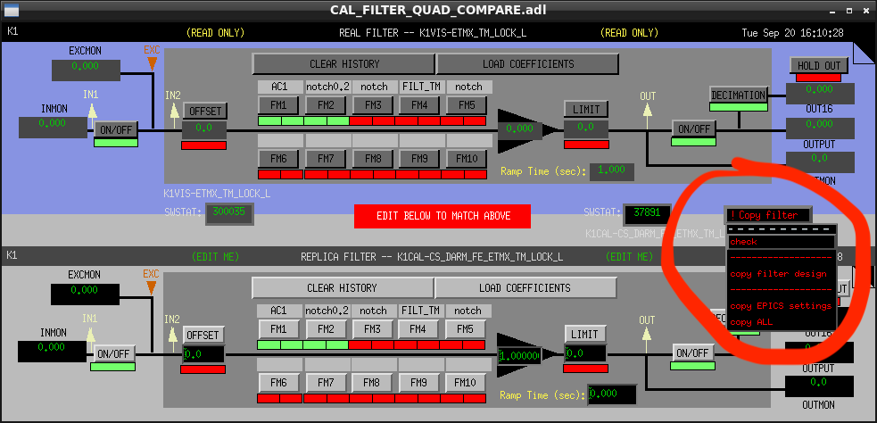
For actuation filter, "making filters" means just a copy of filter design from VIS model to CAL model.
Each filter bank interface can be accessed from
sitemap -> CAL -> CS OVERVIEW -> ACTUATION FUNCTION -> $(OPTIC) ACTUATOR MODEL (See Fig.1).
For sensing function, calibration filters are the inverse function of the filters on OMC (and AS17).
A filter bank interface can be accessed from
sitemap -> CAL -> CS OVERVIEW -> INVERSE SENSING FUNCTION (See Fig.2).
When a number of zeros of an inverse filter is more than one of poles, safety poles are automatically inserted.
In order to reduce wasted safety poles, an inverse filter design is made per a FilterBank.
This means inverse sensing function has 4 filter modules as maximum such as compensation of
OMC-TRANS_DC_{A,B}, OMC-TRANS_DC_SUM, OMC-TRANS_DC_AA and LSC-OMC_DC.
Added safety poles are inserted also on the FilterBanks on the actuation path (CAL-CS_DARM_CTRL_DELAY and CAL-CS_DARM_CFTD_CTRL_DELAY)
which are used for compensating timing/phase mismatch between the actuation and the sensing paths.
